

CPC 203-5761 Installation Instructions Manual
TECHNICAL BULLETIN
Part #: 026-4808 Revision 0 Date: 02/26/2003
Outdoor Humidity Sensor (P/N 203-5761)
Installation Instructions
CPC specs a outdoor relative humidity (RH) sensor with a 0-5VDC output for use in building
control and anti-sweat control applications using CPC input boards.
Specifications
Sensing Element
Accuracy
Stability
Operating
Humidity Range
Digitally profiled thin-film capacitive
±2% RH over the range 20%-90% RH
±1%@ 20°C (68°F) annually for 2 years
0-100% RH
Temperature
Coefficient
Analog Output
Scaling
Input Power
±0.03% RH /°C over 0-60°C (32-140°F)
0-5VDC; 3-wire, observe polarity
0-100% RH
12VDC
Choosing a Mounting Location
The outdoor RH sensor should always be mounted on the north side of the building if in the
Northern Hemisphere, or on the south side if in the Southern Hemisphere. The sensor should be
mounted under an overhang or otherwise out of direct sunlight (if possible).
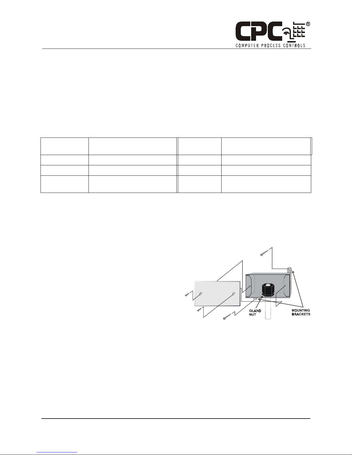
Mounting
1. Secure the rear side of the enclosure to the outside wall
using the two mounting brackets, as shown in Figure 1.
The tube holding the sensor element should point straight
down.
2. If you will be running the sensor cable through the wall
behind the sensor, cut or drill a hole in the wall through
the hole in the enclosure.
COMPUTER PROCESS CONTROLS - http://www.cpcus.com/ Page 1
Figure 1 - Humidity Sensor - Exploded View
Technical Bulletin - Outdoor Humidity Sensor (P/N 203-5761) Installation Instructions
Part #: 026-4808 Revision 0 Date: 02/26/2003
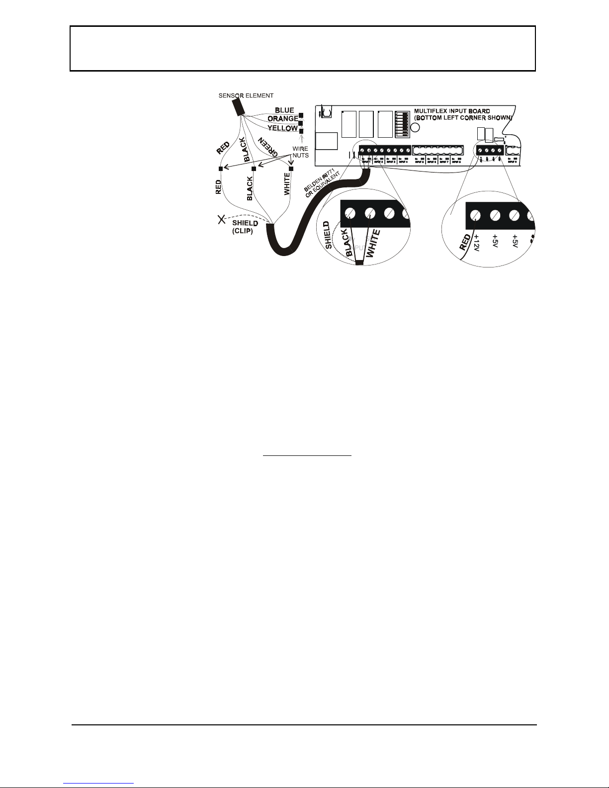
Wiring
NOTE: Do not clip or shorten the
wires leading from the sensor tube!
Shortening the wires will make
future sensor replacement difficult.
1. Use Belden #8771 shielded
three-conductor cable or
equivalent.
2. Connect the RED, BLACK,
and WHITE wires to the
RED, BLACK, and GREEN
wires from the sensor using
the wire nuts supplied in the
kit. Use the remaining wire
nuts to cap and insulate the
unused leads (BLUE,
ORANGE, and YELLOW). Clip the shield (BARE) wire.
3. On the input board, connect the SHIELD and BLACK wires to the 0V terminal. Connect the WHITE wire to the SIG terminal of the input board.
Figure 2 - Sensor and Input Board Wiring
4. Connect the RED wire to the +12V power terminal on the input board.
5. Locate the input dip switch for the sensor point, and set to the OFF position (LEFT for MultiFlex, DOWN for 16AI).
Refer to the input board’s user manual for locations of the input dip switches.
Finishing the Installation
Once the outdoor humidity sensor is mounted and the sensor and board wiring is complete, check the gland
nut that secures the sensor tube assembly (inside the enclosure, as shown in Figure 1) and tighten if necessary. Attach the cover plate (with the foam gasket included) to the sensor enclosure using the screws provided. Tighten all conduit connections, and cap all unused holes
in the sensor enclosure using the caps
provided in the sensor kit. This will protect the wiring from moisture and the elements.
Calibration and Replacement
The sensing element of the 203-5761 duct-mount RH sensor is pre-calibrated and will require no physical
adjustment. If the sensor drifts over time, the sensor can be ‘recalibrated’ by replacing the pluggable sensing element. Contact CPC to order replacement elements (P/N 203-5795).
To replace a sensor element, pull the sensor’s power connection from the input board. Remove the
cover plate of the enclosure. From inside the enclosure, loosen the gland nut that secures the sensor tube,
and press the sensor tube down until it hangs by the wires. Unscrew the slotted cover of the sensor tube to
expose the pluggable RH sensor element.
Note the orientation of the sensor element before unplugging it and plug the new sensor element in
using the same orientation (a pair of needle-nosed pliers might be necessary if it is difficult to line the sensor up with the pins). Replace the slotted cover when finished, and push up on the sensor element cap until
it no longer sticks out through the bottom of the end of the tube. Tighten the gland nut and replace the
cover. There is no other calibration method needed, and no adjustments are present in the unit.
Note: Do not expose sensor element to the fumes of curing RTV silicone rubber. Doing so
will damage the calibration of the element.
COMPUTER PROCESS CONTROLS - http://www.cpcus.com/ Page 2
 Loading...