

CPC 203-5752 Installation Manual
TECHNICAL BULLETIN
Part #: 026-4806 Revision 1 Date: 05/24/ 20 0 5
Wall-mounted RH Sensor and RH/Temperature Sensor
Installation Guide
CPC specs a wall-mounted relative humidity (RH) sensor (P/N 203-5751) and/or RH and temperature sensor (P/N
203-5752) for use in building control and anti-sweat control applications using CPC input boards.
Specifications
General
Input Power 12VDC
Enclosure High-impact plastic, white
Relative Humidity (RH)
Sensing Element Digitally profiled thin-film capacitive
RH Accuracy ±3% RH over the range 20%-90% RH
Stability <0.5% RH per year
Operating Humidity
Range
Analog Output 0-5VDC; 3-wire, observe polarity
Scaling 0-100% RH
0-100% RH
Temperature
Temperature Accuracy ±0.4°F from 32°F to 140°F
Analog Out Resistive, 2-wire, no polarity
Choosing a Mounting Location
Mount the sensor indoors in a central location within the zone to be measured, away from doors, windows, vents,
heaters, and outside walls that could affect temperature readings. The sensor should be at least four feet from the
floor, and no higher than necessary to prevent tampering.
COMPUTER PROCESS CONTROLS - http://www.cpcus.com/ Page 1
Technical Bulletin - Wall-mounted RH Sensor and RH/Temperature Sensor Installation Guide
Part #: 026-4806 Revision 1 Date: 05/24/2005
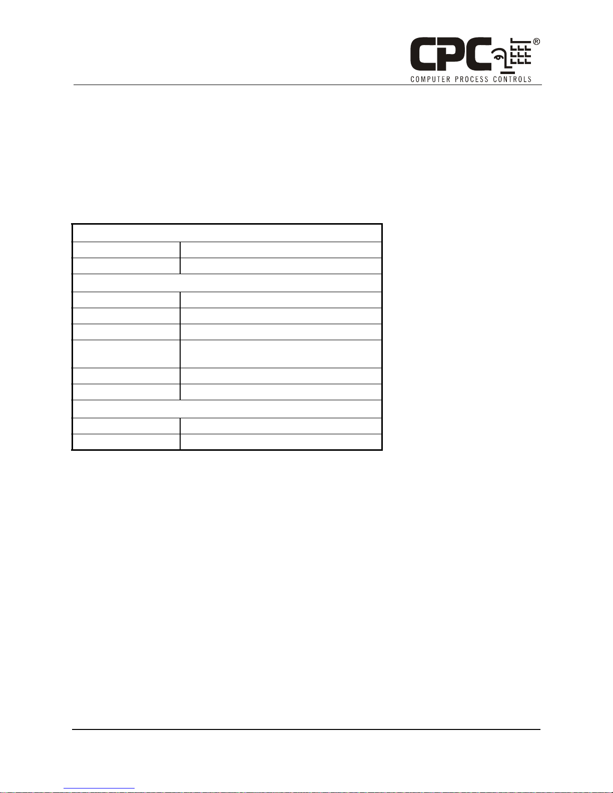
Mounting
1. Insert a screwdriver into the gap in the plastic on the bottom
side of the sensor enclosure, and pry the front part of the
enclosure away from the rear mounting plate. Pull the front
away from the mounting plate until the top separates from the
mounting plate.
2. Remove the punch outs above the wiring connectors so that
the sensor cables can be run into the sensor enclosure (see Fig-
ure 1).
3. Use the pre-made holes to mount the plate on a junction box
using the screws provided, or mount it against a wall or riser .
Do not mount the plate upside down or sideways. The plate
should be mounted with the terminal blocks toward the bottom.
4. If necessary, drill or cut a hole in the wall to allow the sensor
cable to be run through the wall into the sensor’s terminal
block.
Figure 1 - RH/Temp Sensor Back Plate
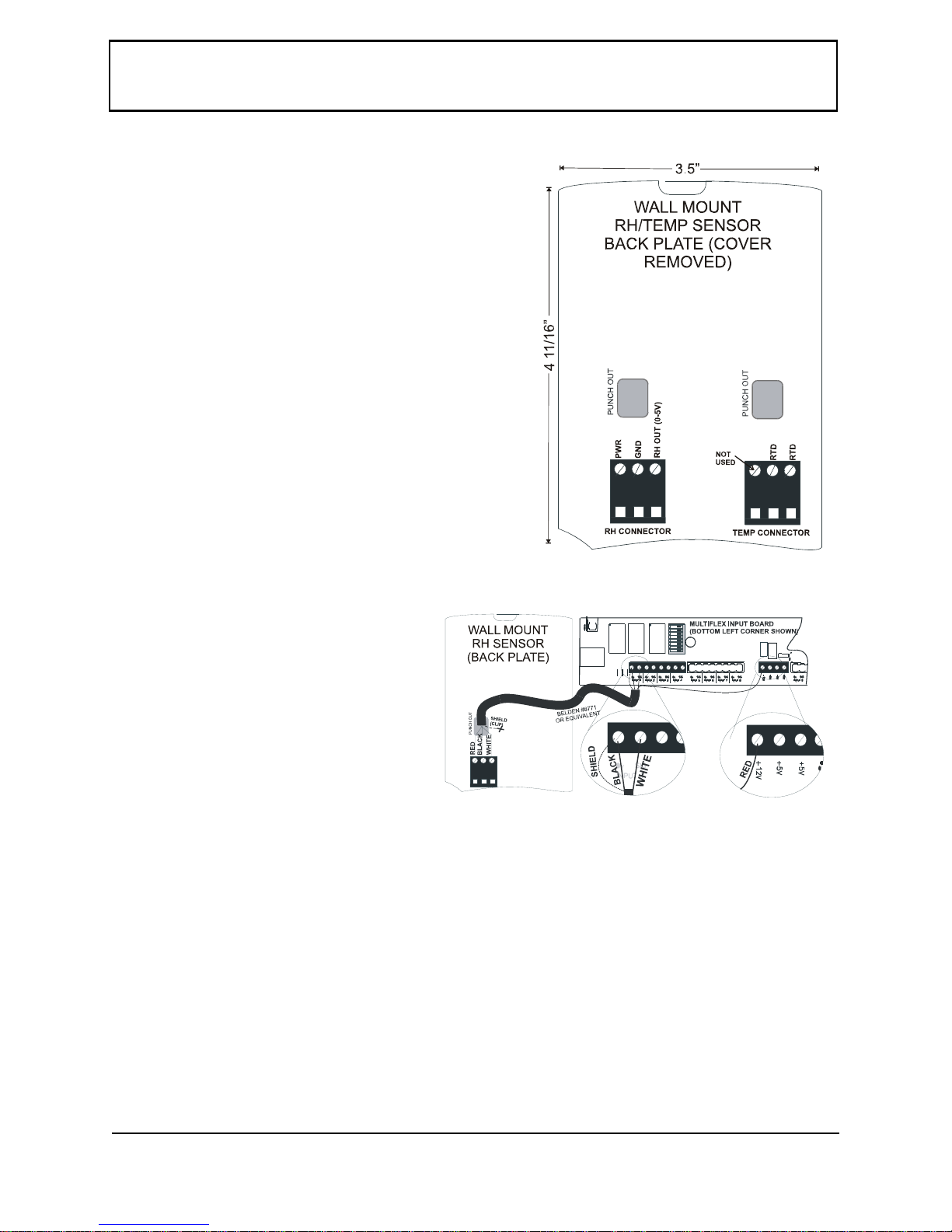
RH Sensor Wiring
1. Use Belden #8771 shielded three-conductor cable
or equivalent.
Note: Seat the connector on the back plate if it
becomes dislodged.
2. Connect the RED, BLACK, and WHITE wires to
the screw terminals the sensor’s connector as
shown in Figure 2. Clip the SHIELD wire.
3. Connect the SHIELD and BLACK wires to the
0V terminal of the input board (under INPUT 1).
Connect the WHITE wire to the SIG terminal of
the input board.
4. Connect the RED wire to the +12V power terminal on the input board.
5. Locate the input dip switch for the sensor point, and set to the OFF position (LEFT for MultiFlex, DOWN for 16AI). Refer to
the input board’s user manual for locations of the input dip switches.
Figure 2 - Sensor and Input Board Wiring
COMPUTER PROCESS CONTROLS - http://www.cpcus.com/ Page 2
 Loading...