

CPC 203-5751 Installation Instructions Manual
TECHNICAL BULLETIN
Part #: 026-4806 Revision 0 Date: 02/26/2003
Wall-Mounted Humidity Sensor (P/N 203-5751)
Installation Instructions
CPC specs a wall-mounted relative humidity (RH) sensor with a 0-5VDC output for use in building control and anti-sweat control applications using CPC input boards.
Specifications
Sensing Element
Accuracy
Stability
Operating
Humidity Range
Temperature
Coefficient
Digitally profiled thin-film capacitive
±2% RH over the range 20%-90% RH
±1%@ 20°C (68°F) annually for 2 years
0-100% RH
±0.03% RH /°C over 0-60°C (32-140°F)
Analog Output
Scaling
Input Power
Enclosure
EMC
Conformance
0-5VDC; 3-wire, observe polarity
0-100% RH
12VDC
High-impact ABS plastic, plenum rated
UL94-5VA, White
EN 50081-1, EN 50082-1, EN 61000-4-4,
EN 61000-4-5, EN 61000-4-3,
ENV 50204, EN 61000-4-6
Choosing a Mounting Location
Mount the sensor indoors in a central location within the zone to be measured, away from doors,
windows, vents, heaters, and outside walls that could affect temperature readings. The sensor
should be at least four feet from the floor, and no higher than necessary to prevent tampering.
Mounting
1. Insert a screwdriver into the gap in the plastic on the bottom
side of the sensor enclosure, and pry the front part of the
enclosure away from the rear mounting plate. Pull the front
away from the mounting plate until the top separates from the
mounting plate.
2. Remove the punch out above the wiring connector so that the
sensor cable can be run into the sensor enclosure (see Figure
1).
3. Use the pre-made holes to mount the plate on a junction box
using the screws provided, or mount it against a wall or riser.
Do not mount the plate upside down or sideways. The plate
should be mounted with the terminal block toward the bottom.
4. If necessary, drill or cut a hole in the wall to allow the sensor
cable to be run through the wall into the sensor’s terminal
block.
COMPUTER PROCESS CONTROLS - http://www.cpcus.com/ Page 1
Figure 1 - Humidity Sensor - Exploded View
Technical Bulletin - Wall-Mounted Humidity Sensor (P/N 203-5751) Installation Instructions
Part #: 026-4806 Revision 0 Date: 02/26/2003
Wiring
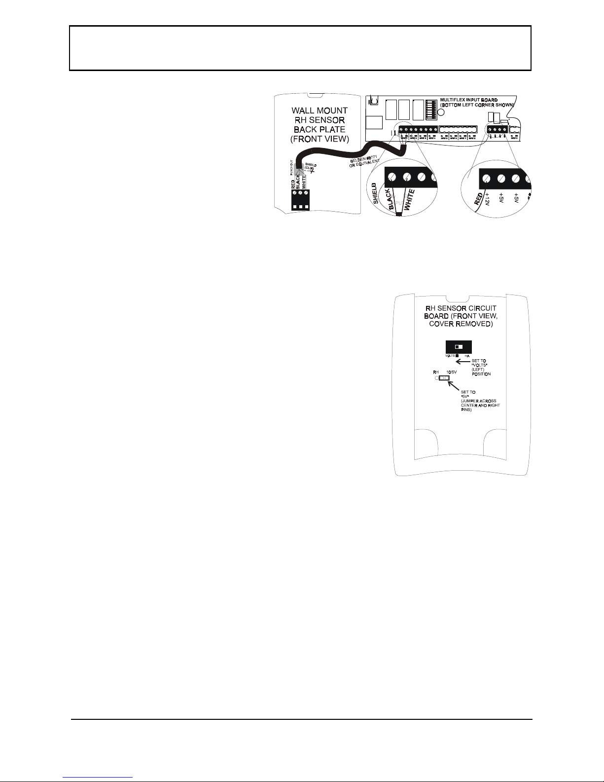
1. Use Belden #8771 shielded three-conductor cable
or equivalent.
2. Connect the RED, BLACK, and WHITE wires to
the screw terminals the sensor’s connector as
shown in Figure 2. Clip the SHIELD wire.
3. Connect the SHIELD and BLACK wires to the
0V terminal of the input board. Connect the
WHITE wire to the SIG terminal of the input
board.
4. Connect the RED wire to the +12V power terminal on the input board.
5. Locate the input dip switch for the sensor point, and set to the OFF position (LEFT for MultiFlex, DOWN for 16AI). Refer to
the input board’s user manual for locations of the input dip switches.
Figure 2 - Sensor and Input Board Wiring
Finishing the Installation
Once the back plate of the sensor is mounted and the sensor and
board wiring is complete:
1. Attach the sensor circuit board enclosure to the mounting plate. Push the top of the
front part onto the mounting plate so the hooked mounting tabs fit underneath the
circuit board enclosure, and push the bottom part down so that the three prongs on
the back of the circuit board fit into the wiring connector. Continue pushing until
the front part is flush with the mounting plate.
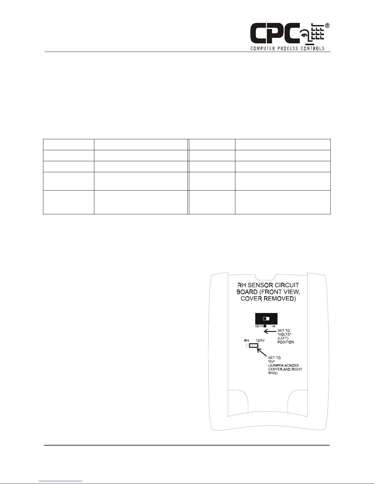
2. Before putting the cover on the sensor circuit board enclosure, check the position of
the switch and the jumper on the front of the circuit board. The switch should be set
to the VOLTS (left) position. The jumper should be set to the 5V position (across
the center and right pins). If either or both of these are in the wrong position, set
them to the correct position. Refer to Figure 3 for positioning.
3. Replace the front cover by inserting the hooked tab at the top of the cover into the
slot on the front of the circuit board enclosure so that it snaps into place. Press the
bottom of the cover until it snaps into the enclosure.
Figure 3 - Switch & Jumper Settings
Calibration and Replacement
The sensing element of the 203-5751 wall-mount RH sensor is pre-calibrated and will require no
physical adjustment. If the sensor drifts over time, the sensor can be ‘recalibrated’ by replacing
the pluggable sensing element. Contact CPC to order replacement elements (P/N 203-5795).
To replace a sensor element, use a screwdriver to pry the sensor circuit board off the mounting
plate. The sensing element is located on the back of the circuit board (see Figure 1). Note the ori-
entation of the sensor element before unplugging it and plug the new sensor element in using
the same orientation. Replace the circuit board when finished. There is no other calibration
method needed, and no adjustments are present in the unit.
Note: Do not expose sensor element to the fumes of curing RTV silicone rubber. Doing so
will damage the calibration of the element.
COMPUTER PROCESS CONTROLS - http://www.cpcus.com/ Page 2
 Loading...