

Page 1
JOHN DEERE
X465, X475, X485, X495, X575, X585 and X595
X700 SERIES (X700, X720, X720se, X7 24, X728, X728se , X729, X740, X744, X748, X748se, X 749)
CAB MOUNTING INSTRUCTIONS
Manufactured by:
BOX 70 • LITCHFIELD, MINNESOTA 55355-0070
A-11271
Phone: (320) 693-3221 Fax: (320) 693-7252
1-800-222-5463
Website: www.800cabline.com
05-10408
November 21, 2006
Page 2

SAFETY INSTRUCTIONS
Read operator’s manual. Be thoroughly familiar with the controls, capabilities, and
proper use of the equipment.
NEVER ALLOW ANY RIDERS.
Thoroughly inspect cab mounting periodically.
Stay alert for hidden hazards and traffic.
Avoid sudden starts, excessive speeds, and sudden stops when operating on hillside,
rough ground and most off-the-road operations.
Use extreme care when working close to fences, ditches, or on hillsides.
Wait for tractor to STOP before dismounting.
Check clearance carefully before driving under any objects.
Avoid operating sideways on a steep slope whenever possible.
ALWAYS buckle safety belt while operating tractor.
Never exceed factory recommended specifications.
DO NOT weld, cut, drill or modify ROPS in any manner unless instructed by
manufacturer.
05-10408
November 21, 2006
Page 3
John Deere X Series
CAB MOUNTING INSTRUCTIONS
Preparation of tractor
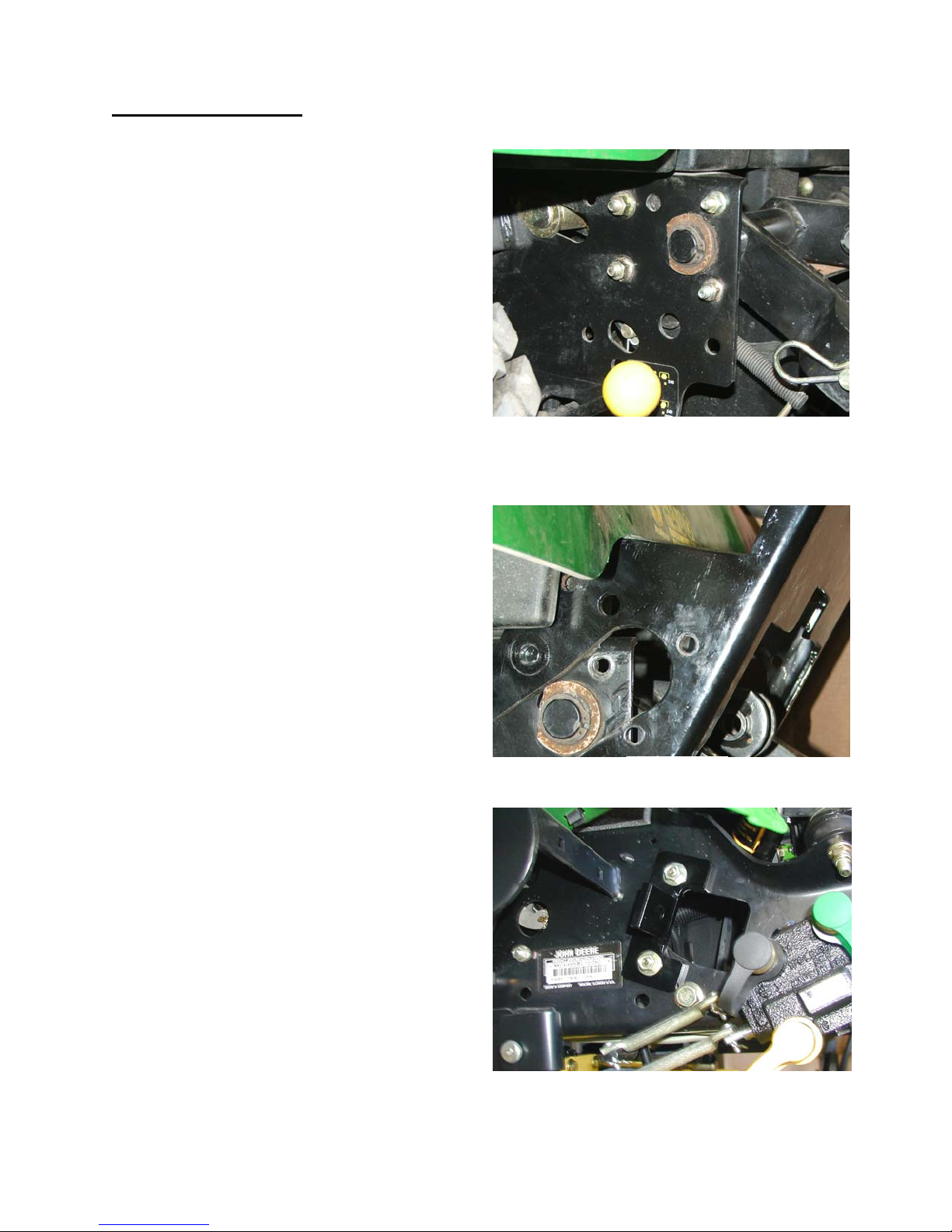
1) Remove the (4) carriage bolts from
each side of the rear frame. See
figure 1. Note – Bolts are not
present on all machines.
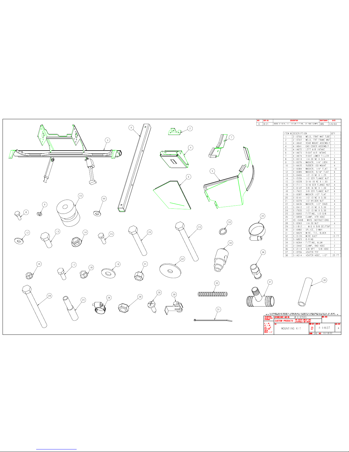
2) Open mounting kit box and layout
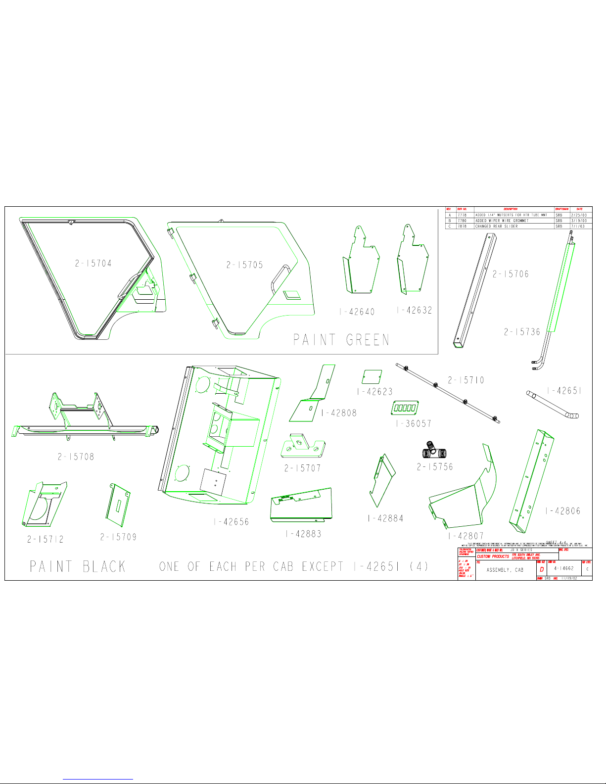
parts. Refer to drawing #4-14637
for mounting parts identification and
part numbers.
3) Removal of the mower deck is
optional. It is easier to install the
front mount with the deck removed.
Open the tractor hood.
4) Install the front frame mount
weldment #2-15707. Use (2) 3/816 x 1.00” bolts, (2) 5/16” flat
washers and (2) 3/8-16 serrated
flange nuts. See figure 3.
5) Install the front mount tube
weldment #2-15706. Use a 1/2-13
x 3.50” bolt with a ½” flat washer
and a 1/2-13 serrated flange nut to
secure. See figure 4.
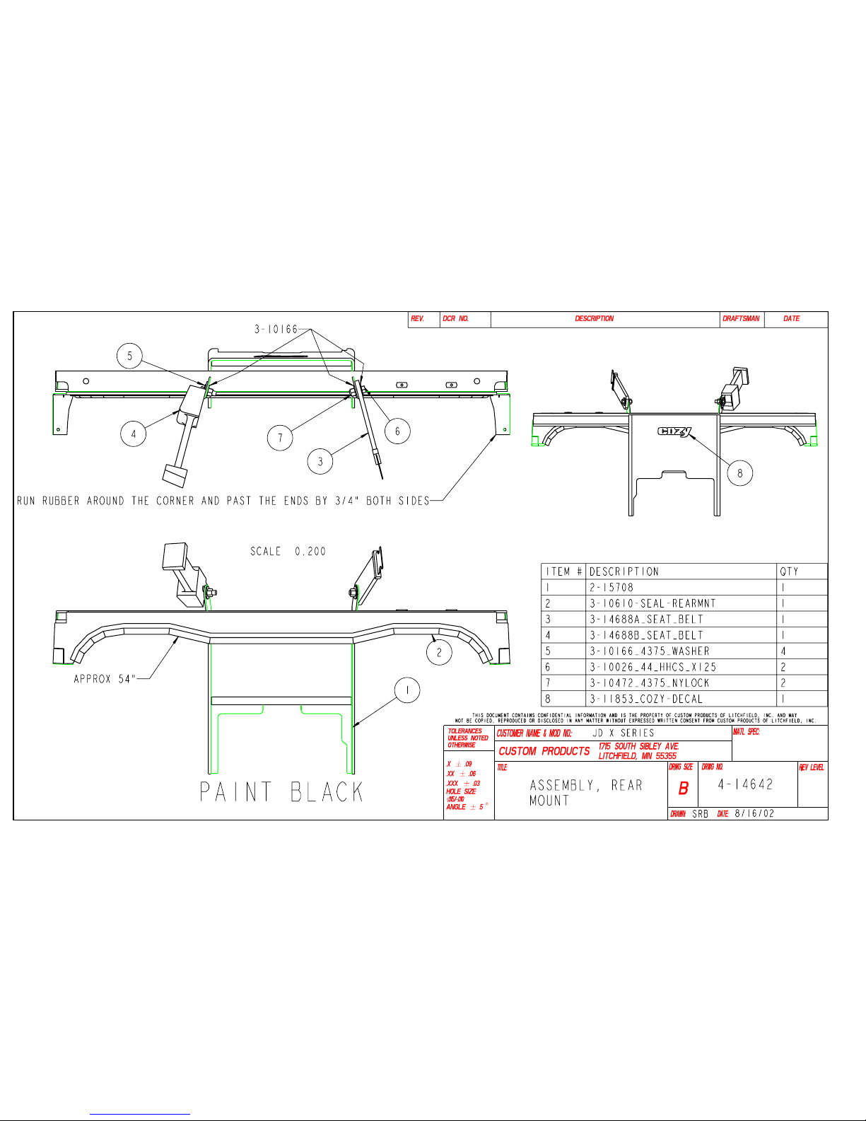
6) Install the rear mount assembly #4-
14642. Use a 1/2-13 x 1.25” bolt
with ½” flat washer and ½” serrated
flange nut on the lower hole on
each side of the mount. Use (2)
3/8-16 x 1.00” bolts with 5/16” flat
washers and 3/8-16 serrated flange
nuts on the (2) front holes on each
side of the mount. Use (2) 5/16-18
x 1.00” bolts with ¼” flat washers
and 5/16-18 serrated flange nuts on
the (2) rear holes on each side of
the mount. See figures 2 and 5.
Figure 1
Figure 2
Figure 3
05-10408
November 21, 2006
Page 4
John Deere X Series
CAB MOUNTING INSTRUCTIONS
Installation of Cab
Raise the cab using the lifting ears on
the roof of the cab. Remove the
shipping stands from the cab.
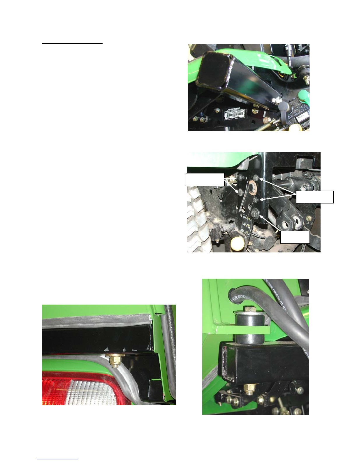
7) Install (4) rubber isolator bushings in
the front and rear cab mounts. See
Figures 7 and 8.
NOTE: The rubber isolators with pipe
bushings should be inserted from the
top-side of the mounts.
8) Lower the cab over the tractor until
the front and rear isolator bushings
are resting on the front and rear
mounts. Line up the holes in the
mounts with the holes in the
isolators. Secure the rear of the cab
using (2) 1/2-13 x 5.00” bolts, (2)
large flat snubbing washers, (2) ½”
flat washers and (2) 1/2-13 nylock
nuts. Secure the front of the cab
using (2) 1/2-13 x 5.50” bolts, (2)
large flat snubbing washers, (2) ½”
flat washers and (2) 1/2-13 nylock
nuts. See Figures 6, 7 and 8.
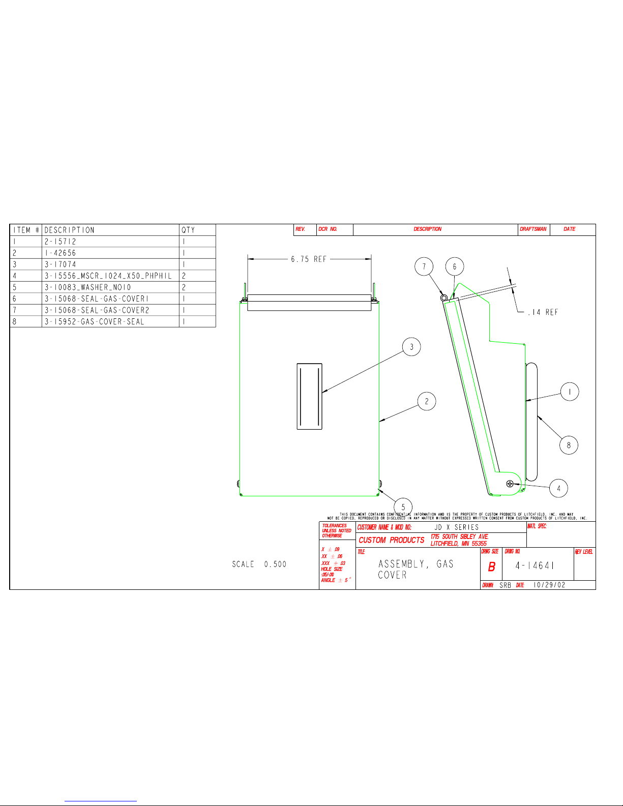
9) Install the filler neck cover assembly
#4-14641. Use (2) 1/4-20 x ¾ bolts,
(2) ¼” flat washers and (2) ¼” lock
washers. See Figure 8.
Figure 6
Figure 4
5/16” Bolts
3/8” Bolts
½” Bolt
Figure 5
Figure 7
November 21, 2006
05-10408
Page 5
John Deere X Series
CAB MOUNTING INSTRUCTIONS
Electrical Hook-up
10) Open the windshield and lift the
tractor hood. Remove the right
side screen assembly from the
tractor console.
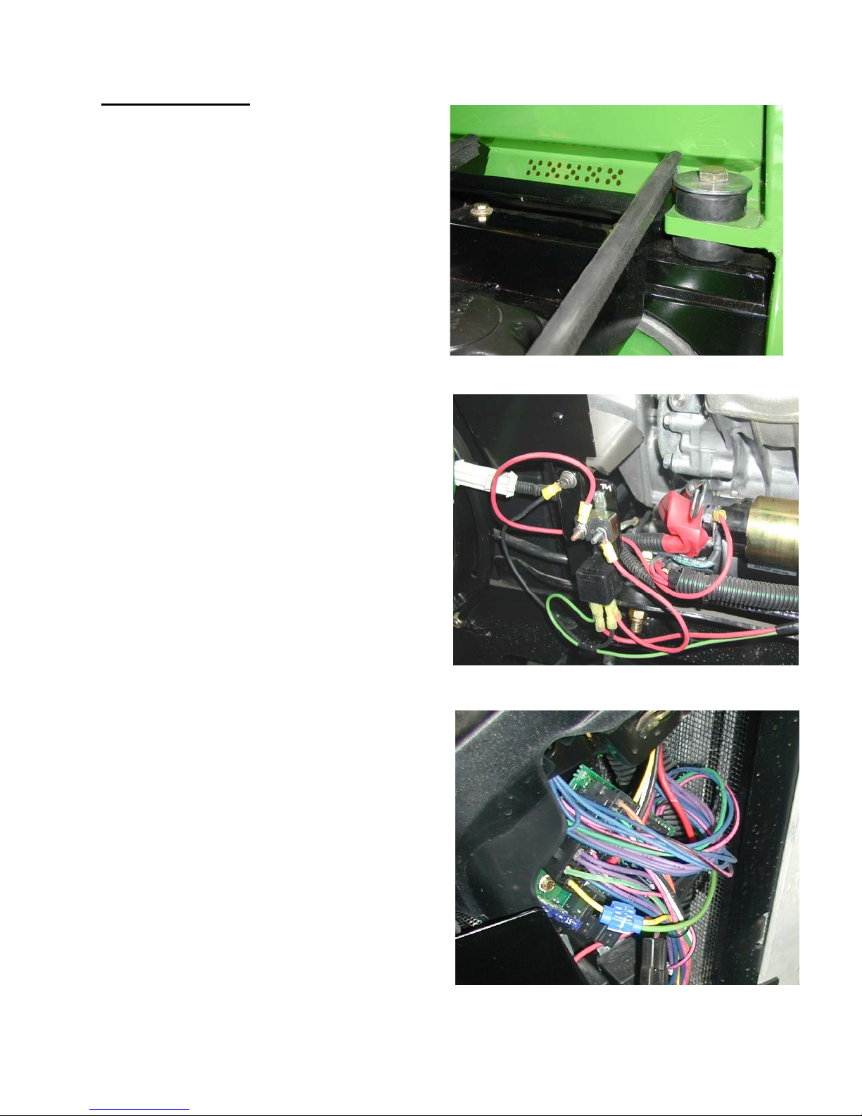
11) Attach the relay assembly bracket
to the tractor. GAS ENGINE -
Remove the lower mounting screw
from the muffler guard on the left
side of the tractor. Attach the
bracket and the ¼” ring terminal on
the 12” black ground wire from the
relay using the mounting screw for
the muffler guard. See figure 9.
DIESEL ENGINE – Mount the relay
bracket to the lower right side of
the machine frame along with the
black 12” ground wire. See figure
11 and 19.
12) Route the 66” light green wire from
the relay to the electrical panel on
the right side of the console. Use
the 3-way wire splice to connect
the light green wire to the yellow
#500 wire on the tractor. See
figure 10.
13) Connect the 3/8” ring terminal on
the 20” red wire from the circuit
breaker to the (+) positive post on
the starter motor. See figure 9.
Gas engine shown – diesel engine
similar.
14) Install a grounding screw. Using
the hole on either side of the rear
mount seal panel, match drill a
5/32” hole into the lower door tube.
Install a #10 x 5/8 self-tapping
screw.
15) Install corrugated wire loom onto
the wires and secure with wire ties
to avoid any hot or moving parts.
Figure 8
Figure 9
Figure 10
05-10408
November 21, 2006
Page 6
John Deere X Series
CAB MOUNTING INSTRUCTIONS
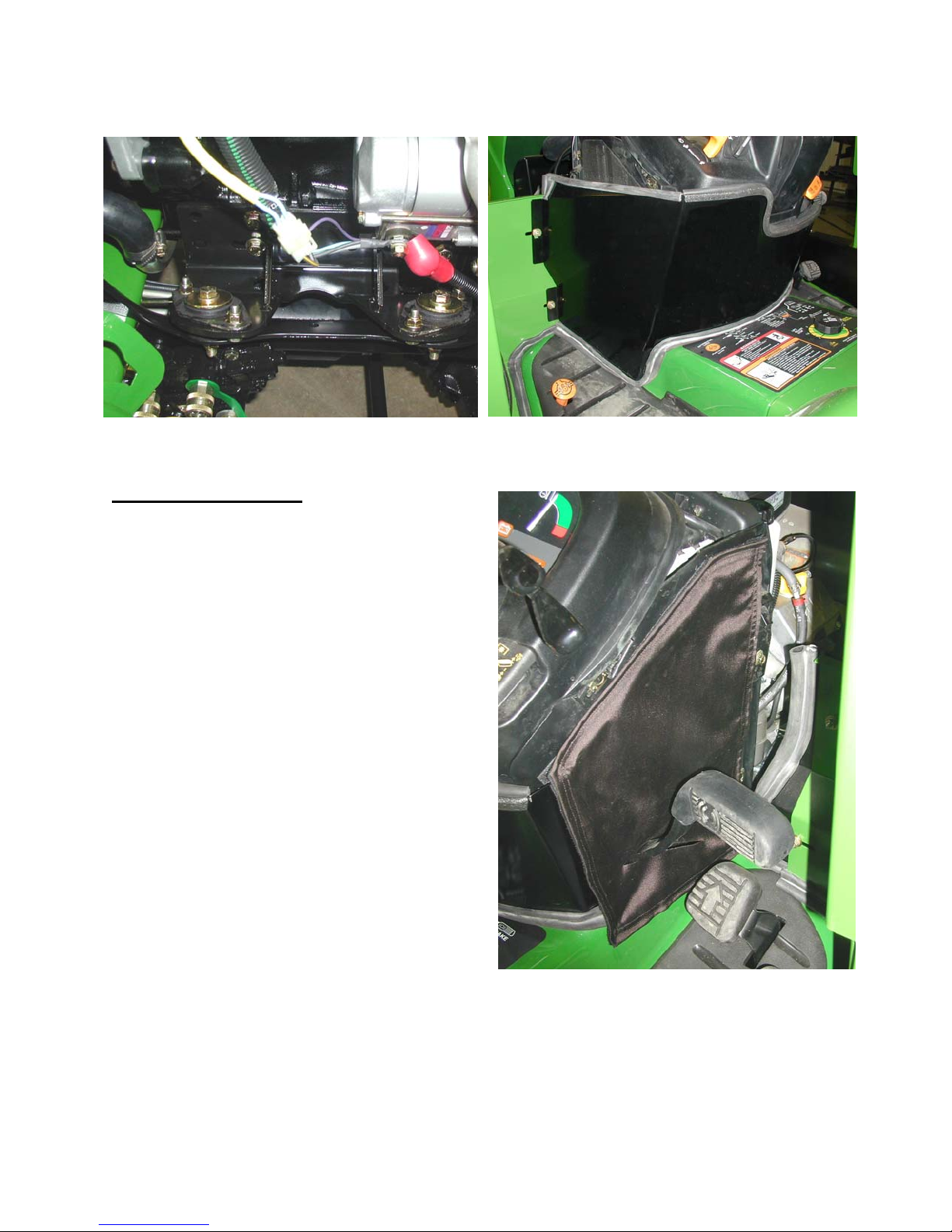
Figure 11
Installing Seal Panels
16) Install the lower left side air intake
panel, #4-14672. Use (2) 1/4-20 x
¾ bolts, (4) ¼” flat washers, (2) ¼”
lock washers and (2) 1/4-20 nuts.
Do not tighten. Position the panel
to seal around the tractor cowl
area. Remove the backing from
the peel and stick velcro on the
back of the right side of the panel
and attach the velcro to the cowl.
Use the adjustment slots on the
panel to get a good seal and
secure. See Figures 12 and 13.
17) Install the nylon lower right air
intake cover, #4-14673, over the
brake pedal. Position the cover
over the right air intake and attach
to the velcro on the left side air
intake assembly. Remove the
backing from the peel and stick
velcro and attach the velcro to the
cowl and step housing to get a
good seal. See figure 13.
Figure 12
Figure 13
05-10408
November 21, 2006
Page 7
John Deere X Series
CAB MOUNTING INSTRUCTIONS
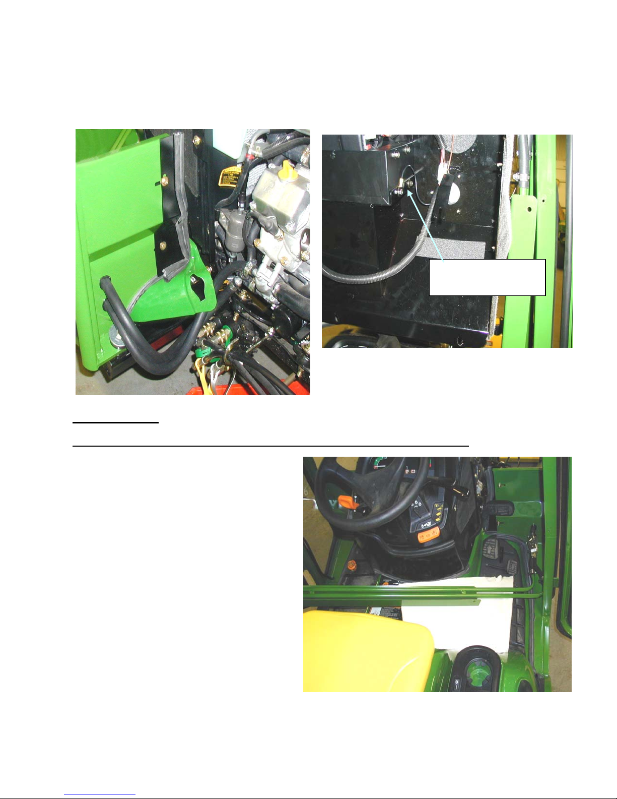
18) Install the lower right filler panel, #4-14674. Use (2) 1/4-20 x ¾” bolts, (4) ¼” flat
washers, (2) ¼” lock washers and (2) 1/4-20 nuts. With the hood closed, use the
adjustment slots to get a good seal and secure. See figure 14.
Heater mount screws
and ground wire
Figure 15
Heater Hookup
The following steps are necessary to achieve coolant flow through the heater core.
19) Lower the cab headliner by removing
the (3) screws in the upper cross
member. Remove the heater valve
covers. Remove the (2) screws on the
cover assembly to remove one half of
the cover and remove the screw from
the bottom of the footpad to remove
the other half. Remove the heater
tube assembly from the right side door
post by removing the (2) mounting
screws. Disconnect the heater wire
harness. Remove the (4) heater
mounting screws. Take the heater
unit out of the headliner and position it
out the left door so it is lower than the
top of the engine. Rest the heater unit
on a stand or table. See figures 15
and 16.
Figure 14
Figure 16
05-10408
November 21, 2006
Page 8
John Deere X Series
d
CAB MOUNTING INSTRUCTIONS
20) Drain the coolant from the tractor. Note: The cab includes an “H” shut off valve which
allows coolant to return to the engine when the valve is in the closed position therefore
not affecting bypass function.
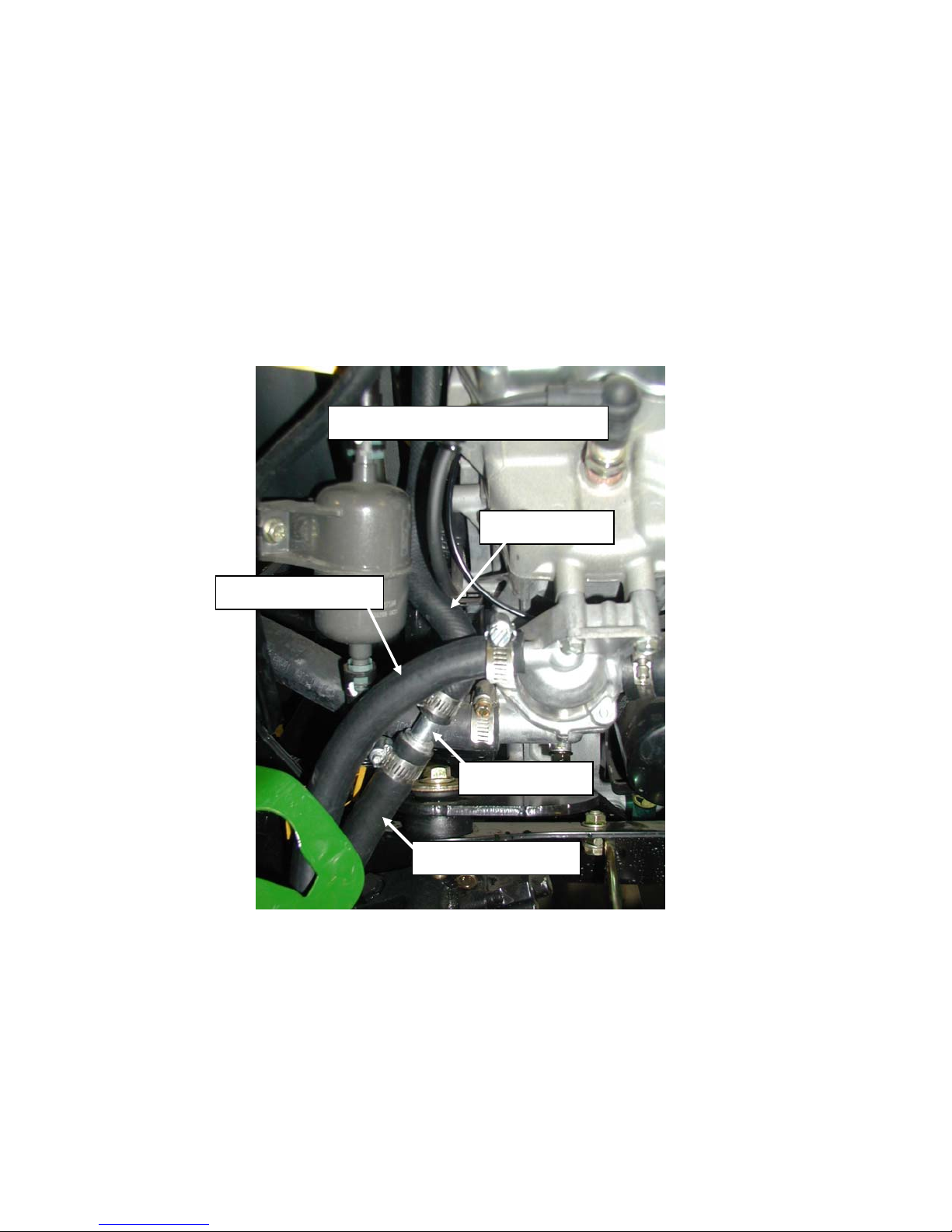
21) Gas Engines Only (Steps 22-23) See Figure 17. Locate the bypass hose that is
connected behind the engine’s thermostat. Disconnect the lower end from the fitting.
Install a 1/2” x 5/8” hose adapter into the end of the bypass hose using a hose clamp to
secure. Install a 3” piece of 1/2” heater hose onto the engine fitting with a hose clamp.
Install a 1/2” x 5/8” hose adapter into the 1/2” hose with a hose clamp. Cut the heater
hose from the upper hole on the front of the cab to a length that will allow it to reach the
hose adapter on the bypass hose without stretching or kinks. Connect it to the hose
adapter with a hose clamp.
n
2
adapter and 1/2” hose not shown
Bypass hose
Lower heater hose
Adapter
Upper heater hose
22) Cut the heater hose from the lower hole on the front of the cab to a length that will allow
it to reach the adapter on the 1/2” hose without stretch or kinks. Connect it with a hose
clamp. See figure 17.
Figure 17
(Gas model shown)
05-10408
November 21, 2006
Page 9
John Deere X Series
CAB MOUNTING INSTRUCTIONS
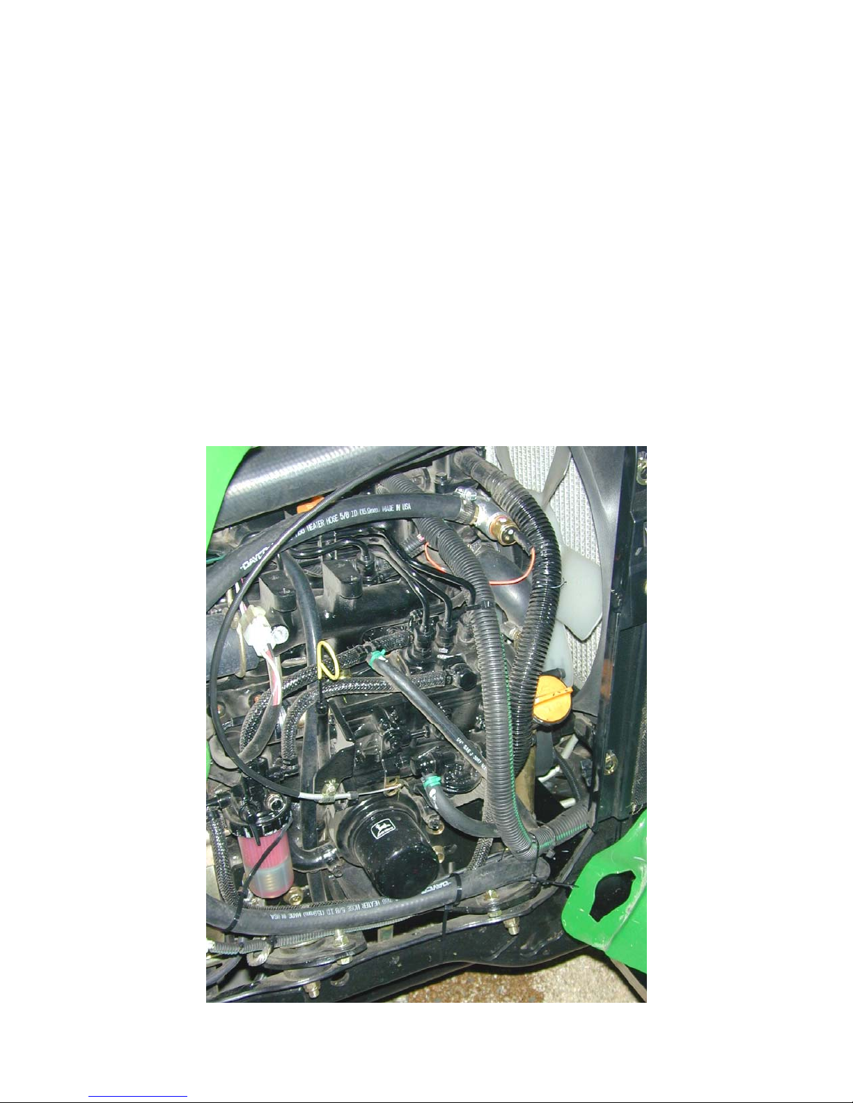
Diesel Engines Steps 24-30 (See Figures 18 and 19)
23) Unplug the temperature sensor and remove the sensor from the thermostat
housing. Set the sensor and seal washer aside for reinstallation.
24) Use pipe seal thread tape or liquid pipe seal compound on all threaded fittings.
Install the provided aluminum fitting into the thermostat housing with the rubber
O-ring washer. Do not overtighten! When the O-ring washer seats, rotate the
fitting so that the side port is accessible.
25) Install a 5/8 hose nipple into the side port of the aluminum fitting.
26) Reinstall the temperature sensor into the end of the aluminum fitting. Connect
the sensor wire.
27) Cut the upper heater hose to a length that will allow it to be connected to the 5/8
hose nipple without contacting any hot or moving parts. Attach the hose to the
hose nipple with a hose clamp.
28) Cut ½” out of the lower radiator hose. Install the heater tee weldment into the
lower radiator hose with (2) hose clamps.
29) Cut the lower heater hose to a length that will allow it to be connected to the
heater tee. Attach the hose with a hose clamp.
Figure 18
November 21, 2006
05-10408
Page 10
John Deere X Series
CAB MOUNTING INSTRUCTIONS
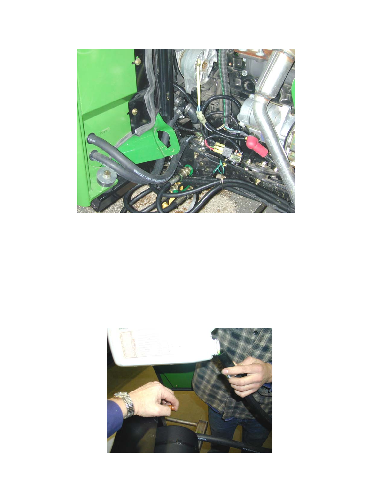
Figure 19
30) Remove the top hose from the heater unit. Pour coola nt into the hose and heater
unit to remove all air from the system. Reinstall the hose to the heater unit. See
figure 20.
31) Refill the radiator.
32) Start the engine and run at fast idle to purge any remaining air from the system
and check for any leaks. Cycle the heater valve on and off several times while
engine is running. Check coolant level.
33) Reinstall the heater unit into the headliner. Reinstall the heater tube
assembly and heater valve covers. Return the headliner to the closed
position being careful not to pinch or twist any hoses or wires.
Figure 20
05-10408
November 21, 2006
Page 11
Page 11 of 25
Page 12
Page 12 of 25
Page 13
Page 13 of 25
Page 14
Page 14 of 25
Page 15
Page 15 of 25
Page 16
Page 16 of 25
Page 17
Page 17 of 25
Page 18
Page 18 of 25
Page 19
Page 19 of 25
Page 20
Page 20 of 25
Page 21
Page 21 of 25
Page 22
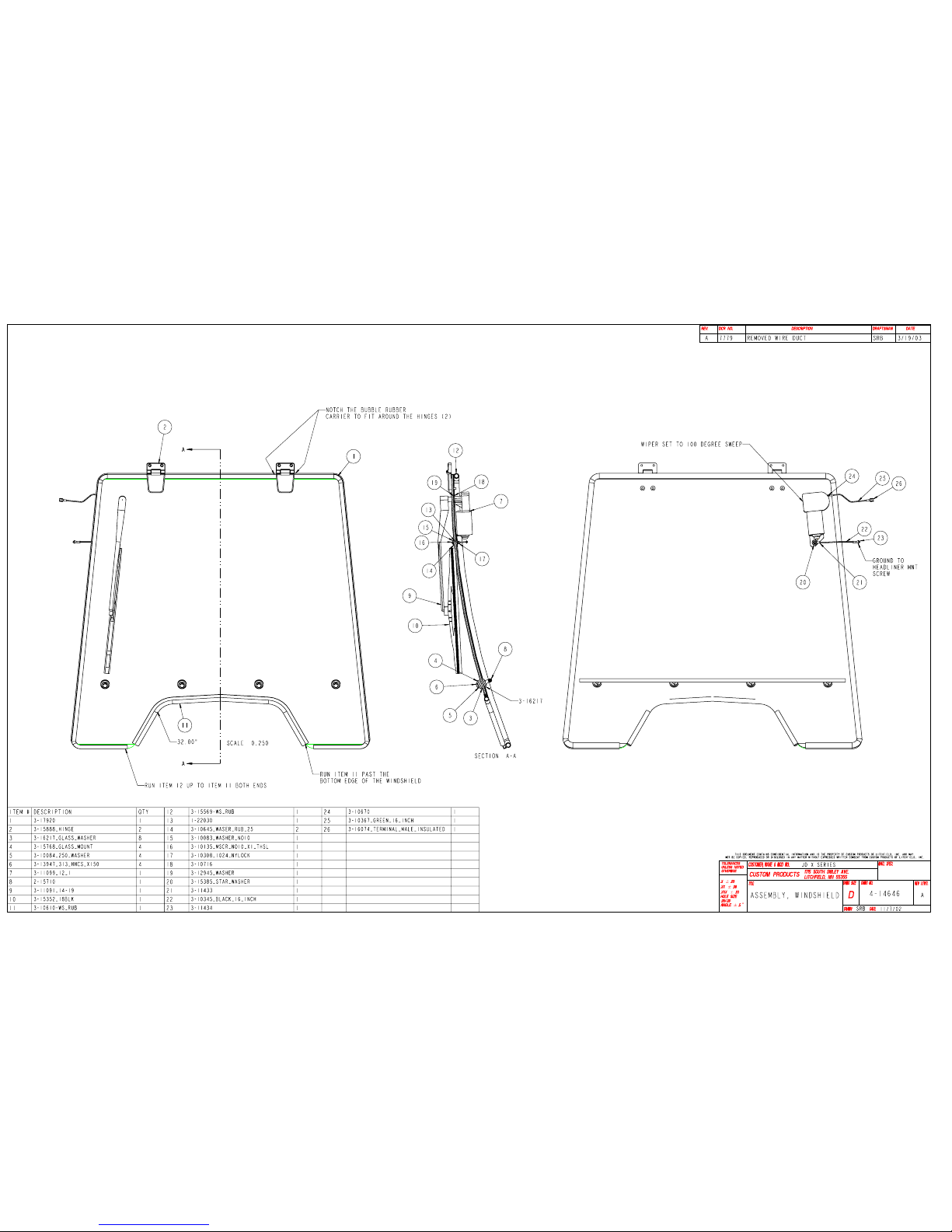
Page 22 of 25
Page 23
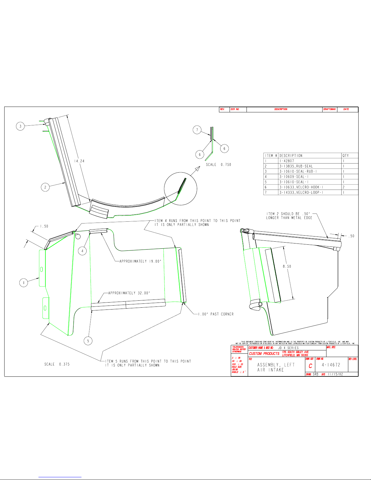
Page 23 of 25
Page 24
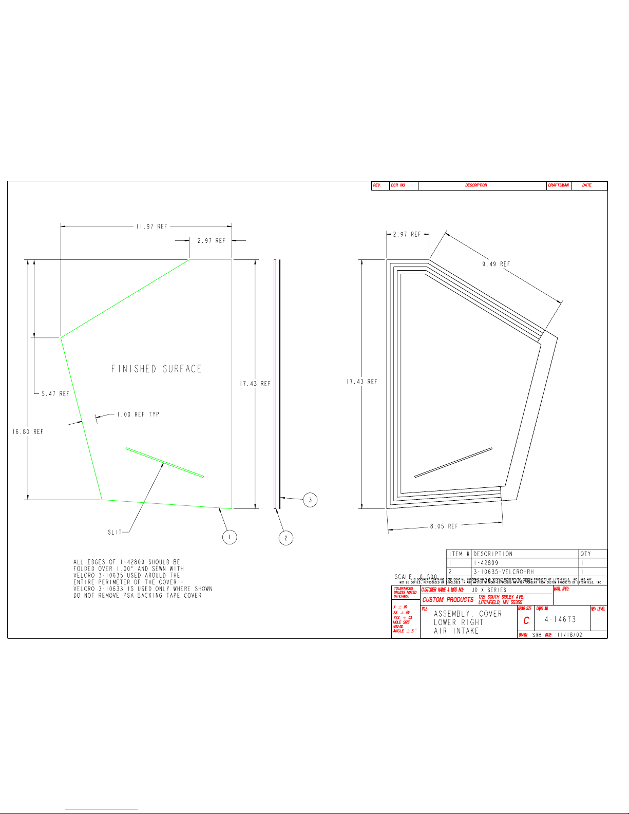
Page 24 of 25
Page 25
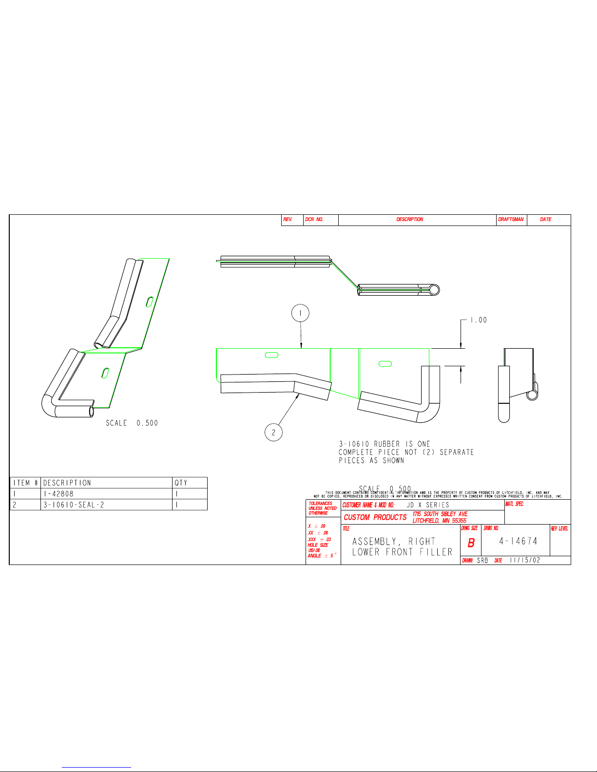
Page 25 of 25
 Loading...