

Page 1

Page 1 of 29
JOHN DEERE 1400-1500 Series Cab
MOUNTING INSTRUCTIONS
Fits with 2 post folding ROPS mower,
sweeper, snow blower or blade options
A-11241
Manufactured by:
(320) 693-3221 Fax: (320) 693-7252
1-800-222-5463
Website address: www.800cabline.com
BOX 70 • LITCHFIELD, MINNESOTA 55355-0070
June 2005
05-10386
Page 2

Page 2 of 29
SAFETY INSTRUCTIONS
Read operator’s manual. Be thoroughly familiar with the controls, capabilities,
and proper use of the equipment.
NEVER ALLOW ANY RIDERS.
IMPORTANT: This cab must only be used on units outfitted with a FOLDING
ROPS (Roll Bar).
DO NOT place this cab on a unit with a non-folding ROPS.
DO NOT remove the top half of the folding ROPS to accommodate this cab.
DO NOT weld, cut, drill, modify or remove the ROPS in any manner unless
instructed by manufacturer.
Thoroughly inspect cab mounting periodically.
Stay alert for hidden hazards and traffic.
Avoid sudden starts, excessive speeds, and sudden stops when operating on
hillside, rough ground and most off-the-road operations.
Use extreme care when working close to fences, ditches, or on hillsides.
Wait for tractor to STOP before dismounting.
Check clearance carefully before driving under any objects.
Avoid operating sideways on a steep slope whenever possible.
ALWAYS buckle safety belt while operating tractor.
Never exceed factory recommended specifications.
June 2005
05-10386
Page 3

)
Page 3 of 29
Cab Installation
2.1) Pull roll bar pins and tip upper roll bar section down.
2.2) Tilt steering column towards seat.
2.3) Tip-up seat towards steering column.
2.4) Open engine cover –Some may choose to remove engine cover and set cover aside.
2.5) From the rear side of the tractor, there are 4 bolts that secure a mount plate to the roll
bar. Doing one side at a time, remove the two bolts that mount the support plate to the
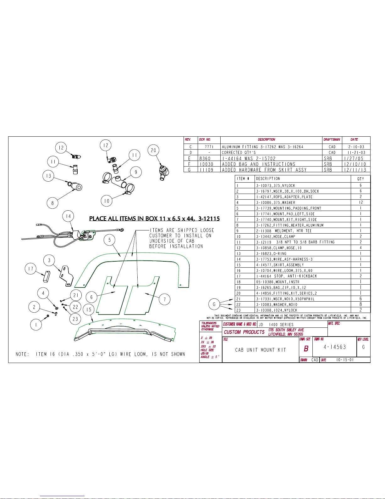
roll bar. Attach the Cab Adapter Plate 1-42147 (Refer to Mount kit Drawing 4-14563) to
the roll bar mount plate (See figure 2-5). Reinstall the same bolts with the pl ate in the
lowest position. Repeat procedure on the other side and install the second Cab Adapter
Plate.
CAB ADAPTER
PLATE 1-42147
MOUNT PLATE
SEAT TILTED UP
CAB ADAPTER
PLATE 1-42147
ROLL BAR BOLTS
(REMOVE AND
RE-INSTALL
FIGURE 2-5
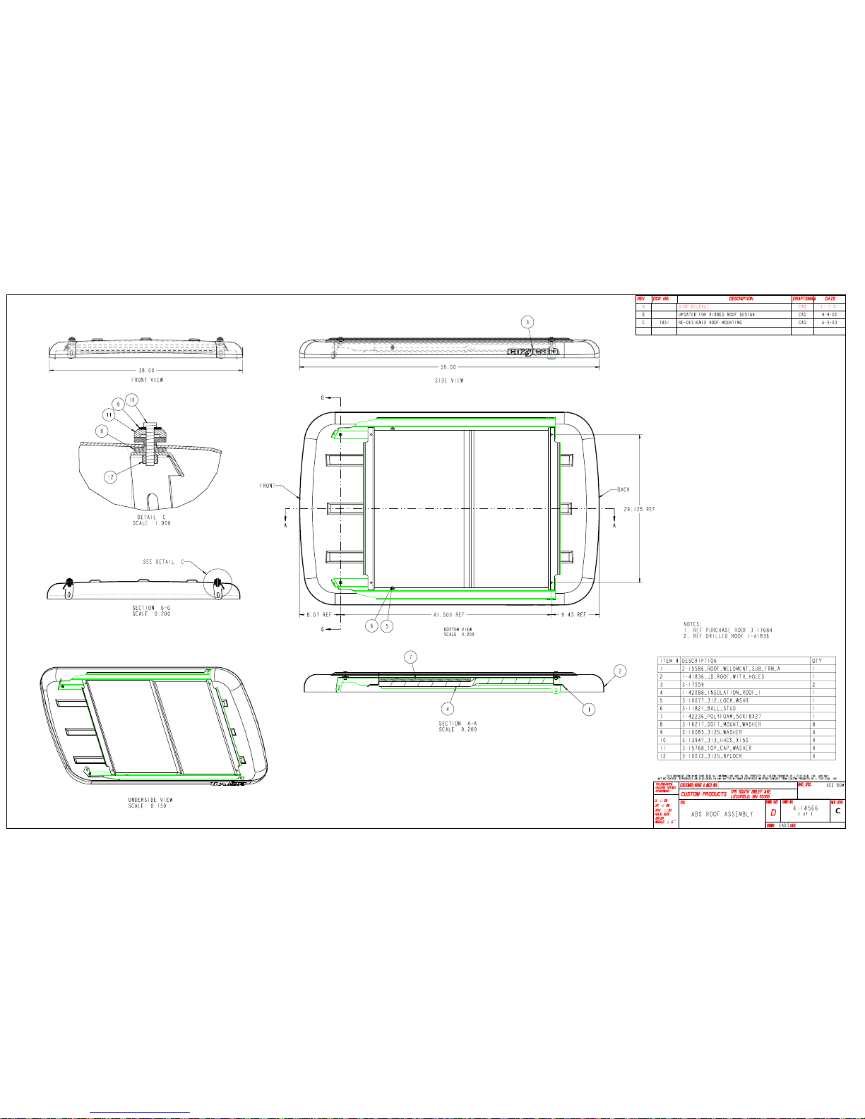
2.6) Next, inspect the cab. There are 2 (Two) lifting brackets mounted at the top o f the cab.
Verify that the bra ckets and fasteners are ti ght prior to lifting the cab. Attach lifting
mechanism, lift, detach and dispose of the shipping pallet and the shipping supports.
2.7) While the cab is in the air, apply the adhesive mount padding, (Refer to items 5, 6 and 7
on mount kit drawing 4-14563).
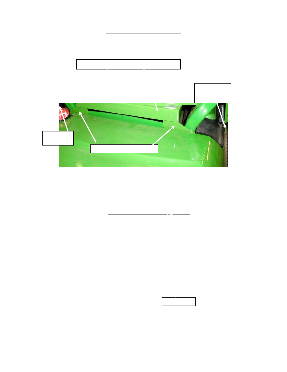
2.8) Position the cab over tractor. Carefully lower the cab down onto the unit making sure the
rear of the cab is pla ced over the cab adapter plates, recently installed. The rea r cab
radius-window will fit into the roll ba r area. Allow the heater hoses to fit arou nd the left
rear side of the cab and the red electrical wire around the right rear side. Center the cab,
side to side. (See figure 2-8).
June 2005
05-10386
Page 4
Page 4 of 29
HEATER
HOSES
Cab Installation (Continued)
CAB SETS OVER CAB ADAPTER PLATES
RED
ELECTRICAL
WIRE
CAB ADAPTER PLATES
FIGURE 2-8
2.9) Secure cab with (2) 3/8” bolts, (4) 3/8”flat washers and (2) 3/8” nylock nuts (Refer to
items 1, 2, 3 and 4 on mount kit drawing 4-14563). See figure 2-9.
FASTENER ITEMS 1, 2 AND 4
FIGURE 2-9
ITEM 3
June 2005
05-10386
Page 5

Page 5 of 29
Cab Installation (Continued)
2.10) From inside the cab, there are four holes located on the cab floor, used for securing the
cab to the frame of your unit. Match-Drill the holes, using a 7/16” diameter drill bit. Verify
there are no obstructions on the underside of the unit’s frame.
2.11) Secure the floor of the cab to the unit using 4 bolts, 8 flat washers and 4 nylock nuts
(Items 1, 2 and 4 on mount kit drawing 4-14563). See figure 2-11.
FLOOR FASTENERS
ITEMS 1 AND 2
Figure 2-11
2.12) The lifting brackets on top of the cab should now be removed and stored for future use if
needed. Check the rear adapter plates and adjust if needed. Tighten all bolts.
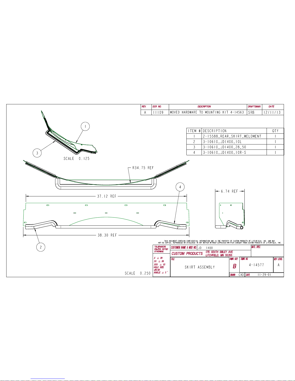
2.13) With the seat tipped forward, install the rear skirt from the inside using the 10-24 UNC
fasteners shipped with the mnt kit. (Re
figure 2-
13.
REAR SKIRT ITEM 15
fer to item 15 on mount kit drawing 4-14563). See
10-24NC FASTENERS
Figure 2-13
June 2005
05-10386
Page 6
(
)
Page 6 of 29
ELECTRICAL MOUNTING
3.1) Disconnect battery.
3.2) The cab is supplied from the factory, pre-wired. Locate the 12 Gauge red wire that runs
down the right rear cab frame tube.
3.3) With the engine hood opened, route the wire to the right inside area of the engine
compartment.
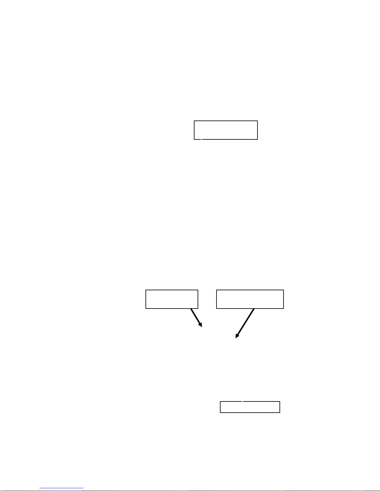
3.4) Locate the wire assembly harness –3 (Refer to Item 14 on mount kit drawing 4-14563).
3.5) Remove two nuts that secure two relays located on the right side of the engine compartment
(See Figure 3-5).
SECURE NUTS
ON FARSIDE
Figure 3-5
3.6) Install the wire assembly harness –3 (See Figure 3-6).
3.7) Re-install the two secure nuts attaching one black wire from the wire assembly.
BLACK WIRE
GROUND
WIRE ASSEMBLY
HARNESS -3
SECURE NUTS
Figure 3-6
June 2005
05-10386
Page 7

OO
Page 7 of 29
3.8) The red wire from the cab hooks attaches to pin number 87 on the black relay.
3.9) The red wire from the silver breaker switch hooks to the positive side of the starter post.
(See figure 3-9).
RED 12 GA WIRE FROM RIGHT REAR
CAB FRAME TO RELAY PIN 87
WIRE ASSEMBLY
HARNESS -3
BREAKER
SWITCH
BLUE WIRE ROUTES
FROM RELAY PIN 86 TO
INGITION CONTROL
POWER SOURCE
BLACK RELAY
RED 12 GA WIRE ROUTES
TO THE POSITIVE
STARTER POST
Figure 3-9
BLUE 14 GAUGE
WIRE FROM PIN 86
WIRE
M
L
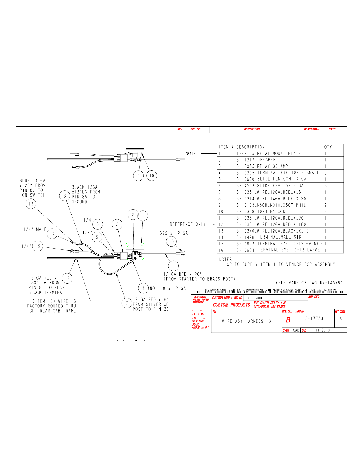
3.10) Connect the blue 14 gauge wire from relay pin 86 to an ignition-on power source that
becomes energized when the ignition key is turned on. (See figure 3-10).
3.11) Cover and secure the wires with ½” plastic wire loom included with the mounting kit.
3.12) Re-connect the battery.
BROWN CONNECTOR
Figure 3-10
June 2005
05-10386
Page 8
(
)
(
)
Page 8 of 29
HEATER HOOKUP INSTRUCTIONS
Pressure/Hot Line to cab heater core;
4.1) With the engine hood opened, drain the radiator by opening the radiator drain plug.
4.2) The pressure-hot hose will be hooked up with the aluminum fitting, one brass fitting,
O-ring washer and a 5/8” hose clamp (Items 8, 11, 12 and 13 on mount kit drawing
4-14563).
4.3) Unplug the electrical sensor and unscrew sensor fitting that is threaded into the water
pump, near the underside of the thermostat location. Set the sensor and washer aside.
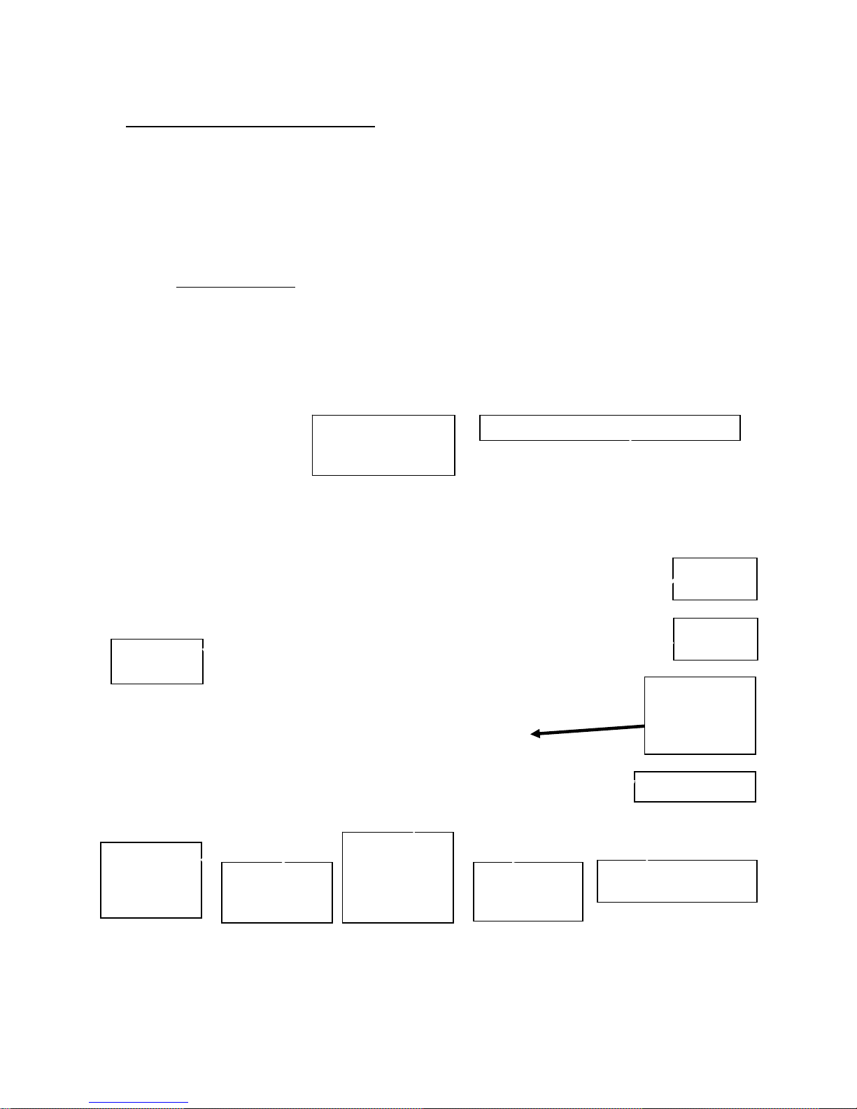
4.4) Use pipe seal thread tape or liquid pipe seal compound on all threaded fittings. Install the
aluminum T-fitting (Item 8) with the rubber O-ring washer (Item 13) into the water pump.
Do not over-tighten
hose fitting (Item 11) can be installed easily.
4.5) Install the brass hose fitting (Item 11) into the aluminum T-fitting (Item 8).
4.6) Reinstall the electrical sensor fitting and washer into the aluminum T-fitting (Item 8).
4.7) The cab is shipped with two 5/8” heater hoses, hooked up from the factory. The outer
line will be the hot-pressure line (See figure 4-2). Route hose and install onto the brass
fitting (Item 11), securing it with a 5/8” hose clamp (Item 12). (See figure 4-1).
! When the O-ring washer seats, orientate the fitting so that the brass
4.10 BRASS
HOSE FITTING
(ITEM 11)
CAB INNER HOSE –RETURN LINE
HOSE-T
(ITEM 9)
FROM
RADIATOR
TO WATER
PUMP
O-RING
ITEM 13
WATER
PUMP
4.7 BRASS
HOSE
FITTING
(ITEM 11)
HOSE CLAMP
ELECTRICAL
SENSOR
ELECTRICAL
SENSOR
PLUG
FITTING AND
BRASS
WASHER
ALUMINUM
T-FITTING
ITEM 8
CAB OUTER HOSE –
HOT PRESSURE
Figure 4-1
June 2005
05-10386
Page 9

(
)
Page 9 of 29
Return Line -from cab heater:
4.8) The return line will be hooked up using a hose-T, two 1-1/4” hose clamps and one brass
fitting (Items 10, 11, 12 and 9 on mount kit drawing 4-14563).
4.9) Select the radiator hose that runs from the radiator to the water pump. Unclamp the hose
at the radiator and remove an internal hose spring if the unit has one inside this hose.
4.10) Measure and mark the radiator hose from the water pump, 8 inches. Cut the radiator
hose, removing a ¾” section of the hose and install the hose-T (Item 9) and the two
1-1/4” hose clamps. Orientate the hose-T fitting so that the brass hose fitting (Item 11)
can be installed easily.
4.11) Re-install the internal hose spring into the radiator hose.
4.12) Install the brass hose fitting with pipe seal tape or liquid pipe seal compound (Item 11)
into the hose-T (Item 9).
4.13) Select the remaining cab hose (This should be the inner-return line), measure to the
fitting, trim to length and install hose onto the brass fitting, securing it with a 5/8” hose
clamp (Item 12).
OUTER HOT-PRESSURE
FROM PUMP)
LINE
INNER-RETURN LINE (TO PUMP
Figure 4-2
HEAT-PULL LEVER
Figure 4-14
Filling the radiator:
4.14) Fill the radiator. Start the engine and let it run at fast idle. From the inside of the cab,
pull the heat-pull lever out (See Figure 4-14), to circulate fluid through the heater lines. It
may take several minutes to purge the air from the lines. Check the radiator level and
add fluid until system is free of air.
June 2005
05-10386
Page 10

Page 10 of 29
ROTARY BRUSH ANTI-KICKBACK STOPS
FOR COZY CAB A-11241 and JOHN DEERE 1400 TRACTORS WITH ROTARY BRUSH
ATTACHMENTS.
A. Even though the rota ry brush frame
appears to have clearance when raised
all the way up, the lin kage of the
assembly could allow the boom of th e
rotary brush to bo unce therefore,
contacting the cab when driving over
rough terrain. Th e Rotary Brush AntiKickback stops will prevent the rotary
brush’s boom from cont acting the ca b
when the brush is raised up.
B. Remove the pin and chain links from
each side of the front underside of the
tractor deck. See Figure B.
C. Re-use the pin to secure the Anti-
kickback Stops # 1-44164. See Figure
C1 and C2.
RE-USE PIN
TO SECURE
ANTI-KICKBACK
D. When the rotary brush is not used, re-
install the chain links and pin. See
Figure D.
TUBE
STOP
6-44164
RE-INSTALL CHAIN
LINKS AND PIN
WHEN NOT USING
ROTARY BRUSH
Figure B
PREVENTS
CAB
DAMAGE
ROTARY
BRUSH
FRAME
Figure C2 Figure C1
Figure D
REMOVE
PIN
REMOVE
CHAIN
LINKS
STOP
BAR
June 2005
05-10386
Page 11

ADDENDUM_05-10386a
Page 11 of 29
INSTALLATION ADDENDUM
John Deere 1400-1500 Series 2
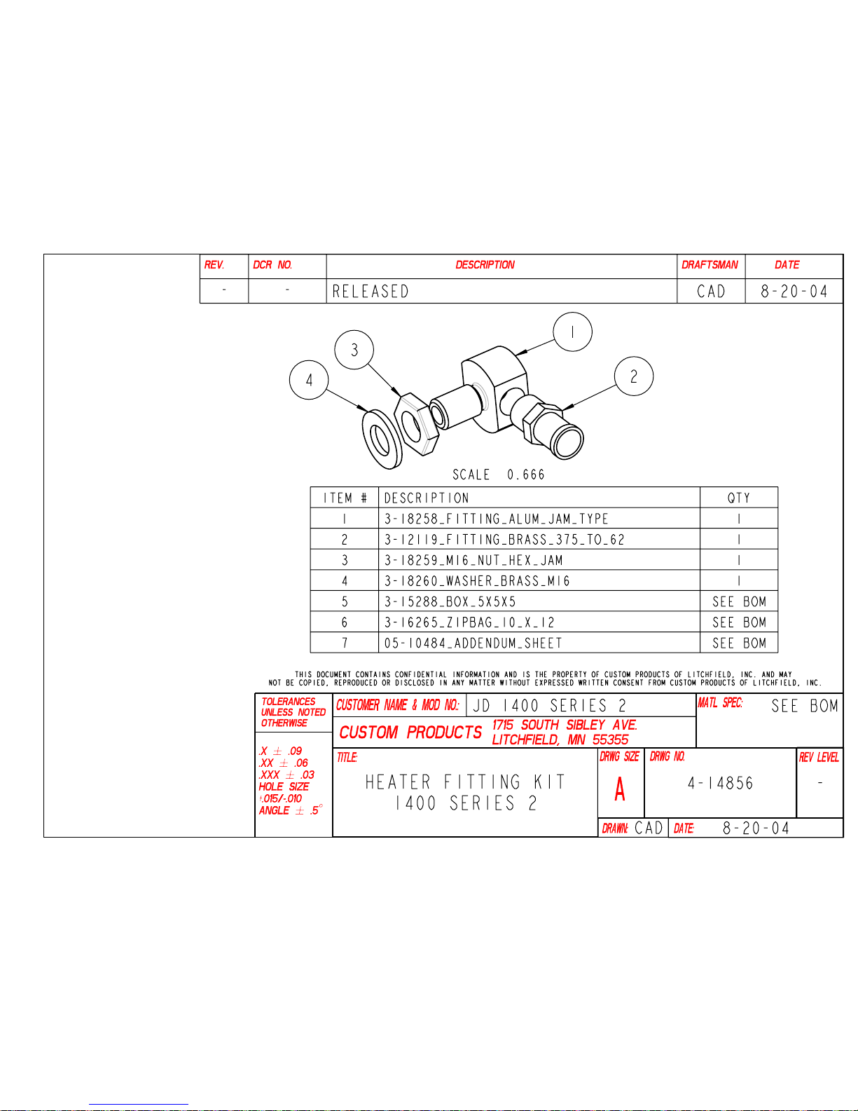
Heater Hook-Up Kit 8-14856
DATE: 8-23-04
FOR COZY CAB A-11241 and JOHN DEERE 1400-1500 Front mount tractors, SERIES 2 MODELS
Manufacturers have been known to change engines, water pumps, alternators and other components to
improve performance of their product at anytime. In the case of John Deere’s 1400-1500 Series 2 models,
the water pump changed and an alternator bracket now makes it difficult to install the proper fittings for the
Cozy Cab heater hookup.
Installation Steps (See Figure A);
1. The engine coolant should be drained, if not done so already.
2. Thread the metric jam nut onto the aluminum fitting.
3. Place brass washer against the jam nut.
4. Remove the threaded seal plug on the thermostat engine area near the alternator bracket, opposite the
side from the temperature sensor.
5. Install the aluminum fitting with the jam nut and washer and position the fitting so that the brass fitting
can be installed easily. Tighten the aluminum fitting by backing the jam nut against the brass washer.
6. Install the brass fitting with pipe thread seal tape into the aluminum fitting.
7. Connect the heater hose and hose clamp supplied with the cab’s heater kit, to the brass fitting.
The lower return line hookup that connects to the lower radiator hose remains unchanged. Refer to cab
mounting instruction manual 05-10386, if not connected.
ALUMINUM
FITTING
METRIC
NUT
BRASS
WASHER
Figure A
BRASS
FITTING
Any you have questions or comments, feel free to contact us at:
BOX 70 • LITCHFIELD, MINNESOTA 55355-0070 (320) 693-3221 Fax: (320) 693-7252 1-800-222-5463
Web-site address: www.800cabline.com
Page 12

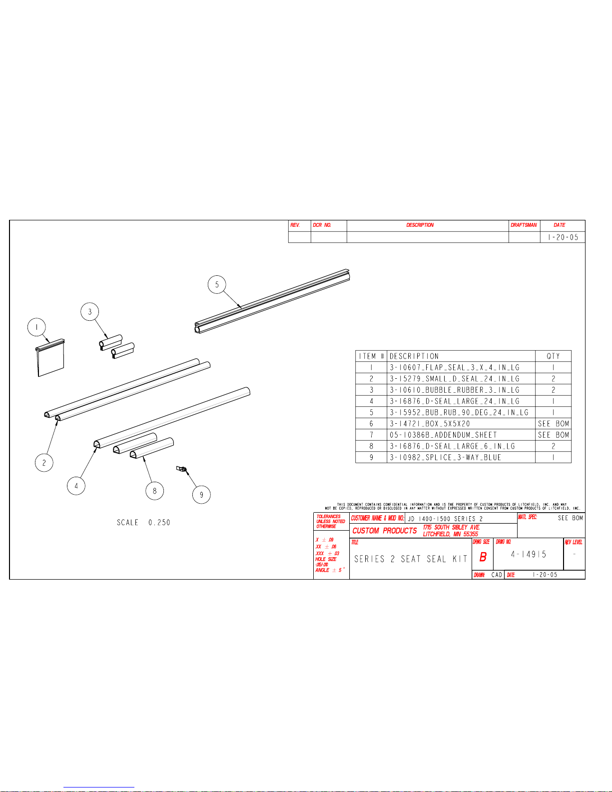
Seat Seal Kit 4-14915 and Addendum Notes
Page 12 of 29
John Deere 1400-1500 Series 2
ADDENDUM_05-10386-b
DATE: 1-10-05
FOR COZY CAB A-11241 and JOHN DEERE
1400-1500 Front mount tractors, SERIES 2
MODELS
B1. Electrical wiring revision; In step 3.10 of the
mounting instruction manual states connecting
the blue wire from the wire relay harness to a
brown connector located under the seat. Series
2 models no longer have this brown connector.
Using a test light, locate a control wire that
becomes positive (+) when the key switch is
turned on. Remove the blade connector and
splice-connect the blue wire from the relay pin 86
of the wire relay harness using a blue 3-way
splice (3-10982) supplied with this addendum to a
control wire. Refer to drawing 3-17753 in the
mounting instruction manual.
B2. Heater hookup comments; Units vary
depending on the features of the tractor. A
combination of fittings and additional shimming of
the alternator may be needed to install the heater
hookup fittings.
(1) 3-10607 x 4” LG
Figure 2
(1) 3-10610 x 6” LG
B3. Install Seat Seal Kit 4-14915.
See figures 1-7.
(1) 3-17865 x 24” LG
Figure 1
Figure 3
(1) 3-18829 x 24” LG
Figure 4
Page 13

Seat Seal Kit 4-14915 and Addendum Notes
Page 13 of 29
John Deere 1400-1500 Series 2
(1) 3-15279 x 24” LG
(1) 3-10610 x 3” LG
(1) 3-18829 x 24” LG
Figure 5
(1) 3-15279 x 24” LG
ADDENDUM_05-10386-b
Figure 6
Figure 7
(2) 3-17865 x 6” LG
(each side)
Any you have questions or comments, feel free to contact us
at:
BOX 70 • LITCHFIELD, MINNESOTA 55355-0070 (320) 693-
3221 Fax: (320) 693-7252 1-800-222-5463
Web-site address: www.800cabline.com
Page 14
Page 14 of 29
Page 15

Page 15 of 29
Page 16
Page 16 of 29
Page 17
Page 17 of 29
Page 18

Page 18 of 29
Page 19
Page 19 of 29
Page 20
Page 20 of 29
Page 21
Page 21 of 29
Page 22
Page 22 of 29
Page 23
Page 23 of 29
Page 24
Page 25
Page 26
Page 26 of 29
Page 27
Page 28
Page 28 of 29
Page 29
Page 29 of 29
 Loading...