

Page 1
JOHN DEERE
Page 1 of 29
4500, 4510, 4600, 4610, 4700 and 4710
CAB MOUNTING INSTRUCTIONS
Fits with 460 loader and over 2 post
Non-Folding and Fol ding ROPS Models
Manufactured by:
BOX 718 • LITCHFIELD, MINNESOTA 55355
(320) 693-3221 Fax: (320) 693-7252
www.800cabline.com
A-11202
05-10357
June 2003
Page 2

SAFETY INSTRUCTIONS
Page 2 of 29
Read operator’s manual. Be thoroughly familiar with the controls, capabilities, and
proper use of the equipment.
NEVER ALLOW ANY RIDERS.
IMPORTANT: This cab must only be used on tractors outfitted with a NON-FOLDING
OR FOLDING ROPS.
DO NOT remove the top half of a folding ROPS to accommodate this cab.
Thoroughly inspect cab mounting periodically.
Stay alert for hidden hazards and traffic.
Avoid sudden starts, excessive speeds, and sudden stops when operating on hillside,
rough ground and most off-the-road operations.
Use extreme care when working close to fences, ditches, or on hillsides.
Wait for tractor to STOP before dismounting.
Check clearance carefully before driving under any objects.
Avoid operating sideways on a steep slope whenever possible.
ALWAYS buckle safety belt while operating tractor.
Never exceed factory recommended specifications.
DO NOT weld, cut drill or modify ROPS in any manner unless instructed by
manufacturer.
05-10357
June 2003
Page 3
John Deere 4500, 4510, 4600, 4610, 4700 and 4710
OU
Page 3 of 29
MOUNTING INSTRUCTIONS
Preparation of tractor
1) Remove grab handles from fenders.
2) Open mounting kit box and layout parts.
3) Remove warning lights from roll bar. Attach warning lights to dual light mount
brackets 7-15661 & 7-15662, using hardware provided: (4) 8mm x 25mm cap
screws & (4) 5/16” lock-washers.
4) Remove side engine panels.
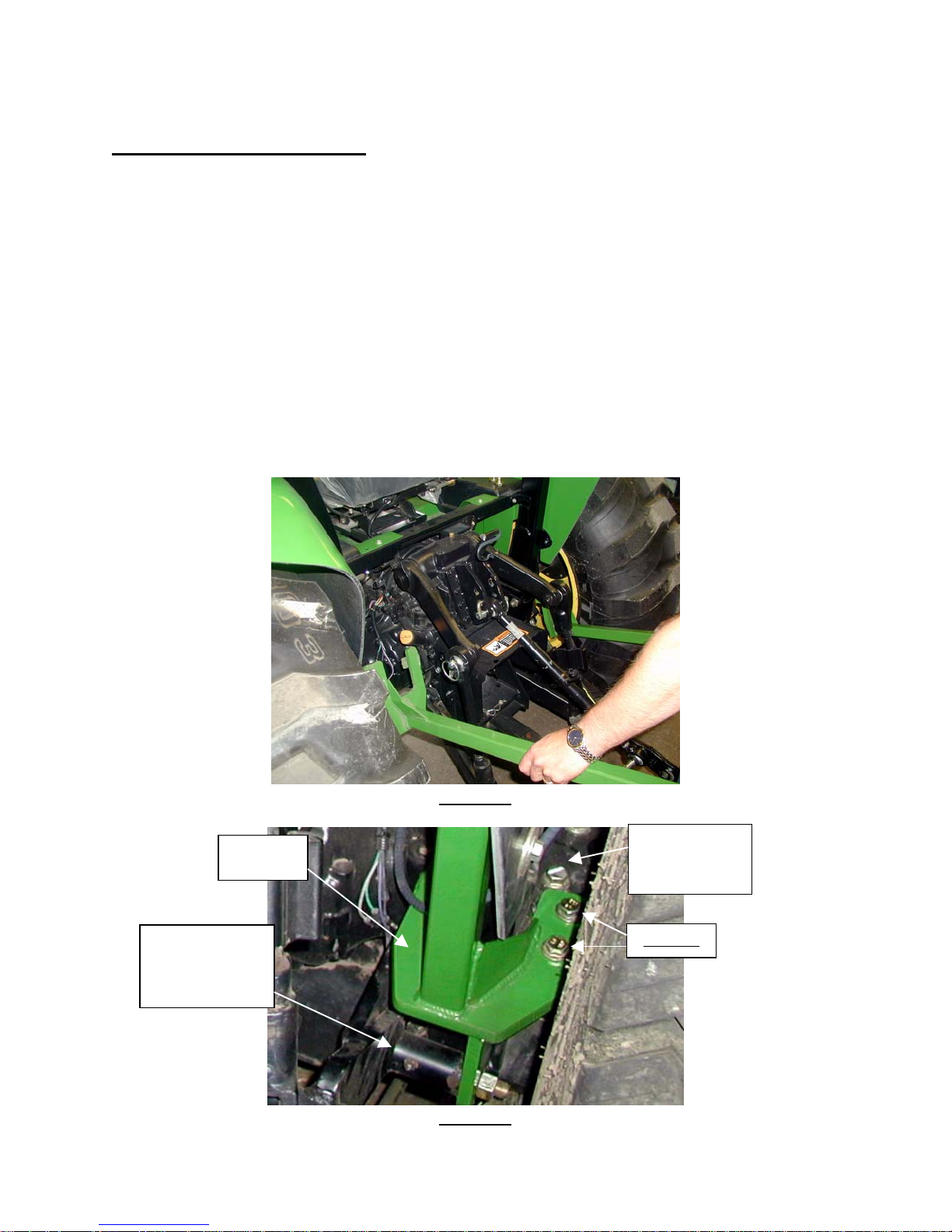
5) Attach rear mount using (4) ½”x 2” bolts, (8) ½” flat washers, and (4) ½” nylock nuts.
Set the rear mount bracket on top of the tractor’s rear mount location (Figures 1& 2).
NOTE: If the tractor is equipped with a mid-mount mower, use the bracket on the
bottom of the rear mount assembly to attach the outer side of the mower pivot bracket,
as shown in Figure 2.
REAR
M
NT
(NOTE 5)
EXAMPLE OF
MID MOUNT
MOWER UNIT
Figure 1
TRACTOR’S
REAR
MOUNT
NOTE 5
Figure 2
05-10357
June 2003
Page 4
John Deere 4500, 4510, 4600, 4610, 4700 and 4710
OU
#3
89
Page 4 of 29
MOUNTING INSTRUCTIONS (Continued)
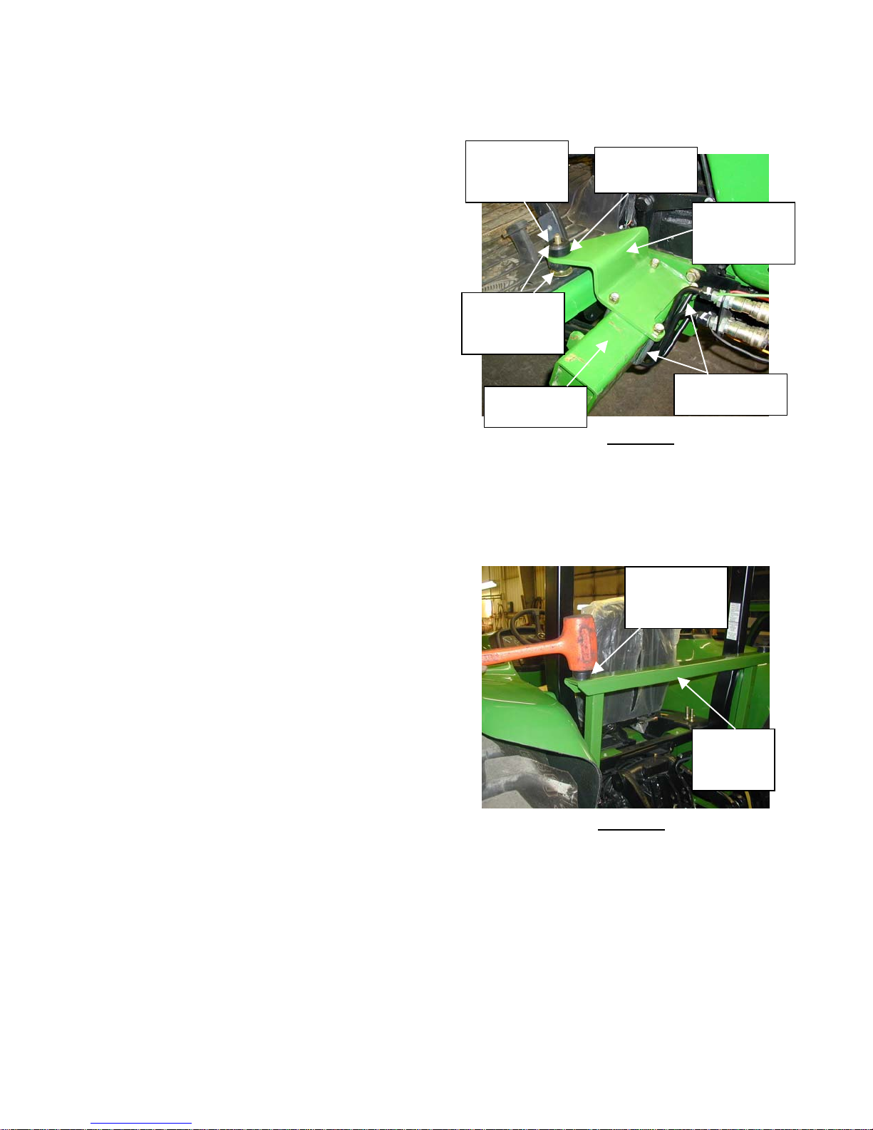
6) Attach front mounts #6-40872 (RH) and
#6-40888 (LH) to JD loader mounts
using (4) ½” u-bolts #3-17489, (8) small
flat washers #3-12466, (2) spacer
washers 6-40606 and (8) ½” nylock nuts
#3-10379.
7) Leave loose until rubber isolators and
bolts are installed (See Figure 3). Note
that there are distinct left and right front
mounts.
NOTE: If the tractor is not equipped with
loader mount brackets, they must be
purchased from JOHN DEERE.
7a) Install (2) rubber isolator bushings #316635 in front mounts with (2) spacer
washers, #6-40606 on the top side of each
front mount plate. (See Figure 3).
7b) Install rubber isolators 3-16635 into
rear mount 2-15370.
RUBBER
ISOLATOR
#3-16635
FLAT
WASHERS
#3-16830
JD LOADER
M
(Note 7A)
#6-40606
FRONT RH
MOUNT
#6-40872
½” U-BOLTS
-174
NT
Figure 3
NOTE: Rubber isolators with pipe bushing
should be inserted from top side of mount.
8) Remove the “Slow Moving Vehicle” sign
from the rear of the seat. Attach the
lower window rubber. If no holes are
present, drill two 5/16” diameter holes
that are 6” apart (centered horizontally
on window).
9) Attach “Slow Moving Vehicle” sign into
holes using ¼” hardware provided and
stainless steel standoffs.
10) Tilt seat forward against steering wheel.
RUBBER
ISOLATOR
#3-16635
REAR
MOUNT
#2-15370
Figure 4
05-10357
June 2003
Page 5
John Deere 4500, 4510, 4600, 4610, 4700 and 4710
OPS
(
)
OPS
SC
S
C
(
)
Page 5 of 29
MOUNTING INSTRUCTIONS (Continued)
Installation of cab
12) Remove cab from shipping stand.
FOLDING ROPS VS. NON-FOLDING
ROPS MODELS;
13) Note: Tractors equipped with the
taller Folding ROPS need
clearance to the roof shell area from
inside the cab. Remove the ROPS
cover panel 8-14617. The poly-
fabric will have a factory pre-cut slot
to allow the Folding ROPS to fit into
the roof shell area when cab is
lowered on to the tractor. Refer to
Figure 18.
14) Note: Models with the shorter Non-
Folding ROPS do not need panel
8-14617 removed. The shorter
ROPS clears and fits under the
cover panel.
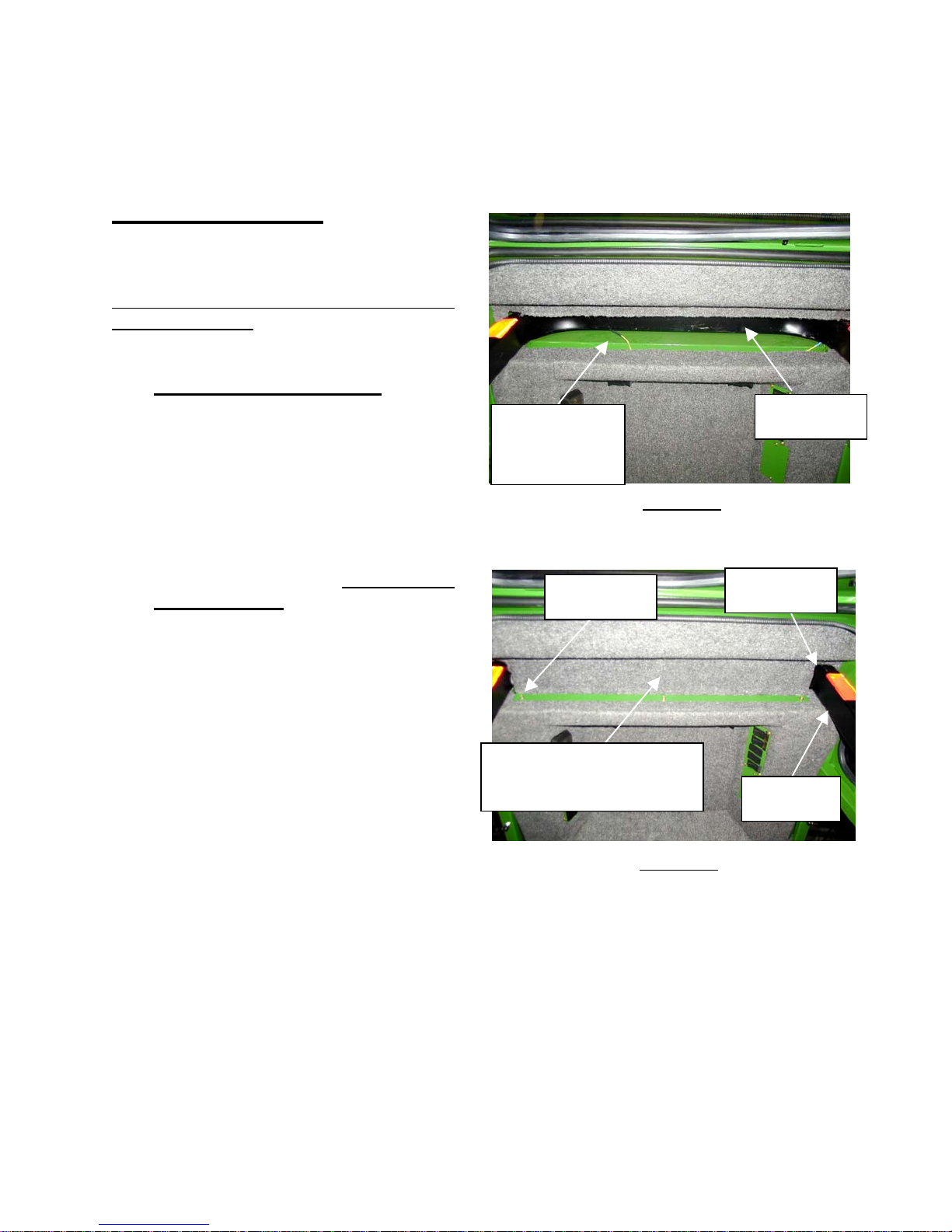
15) Lower cab over roll bar until cab
contacts front and rear isolator
bushings. (Guide Folding ROPS into
the roof shell area). Secure cab to
mounts using (4) ½” x 3 ¼” bolts, (8)
large flat washers, and (4) lock-nuts.
See Figures 3, 4 and 15.
16) If cover panel 8-14617 was
removed, re-install and secure with
(6) 10-24unc screws. See Figure
18.
NOTE 15
FACTORY
CUT SLOT IN
-
Figure 15
FOLDING ROPS MODEL SHOWN
#10-24UNC
REW
(Remove and re-install)
COVER PANEL #8-14617
(FOLDING ROPS ONLY)
Figure 18
FOLDING ROPS MODEL SHOWN
FOLDING
R
TUCK
FABRI
FOLDING
R
05-10357
June 2003
Page 6
John Deere 4500, 4510, 4600, 4610, 4700 & 4710
Page 6 of 29
CAB MOUNTING INSTRUCTIONS (Continued)
17) Loosen lifting ear bolts, tilt lifting ears down, and tighten bolts.
LEFT
FOOT
POCKET
#4-14392
Figure 5
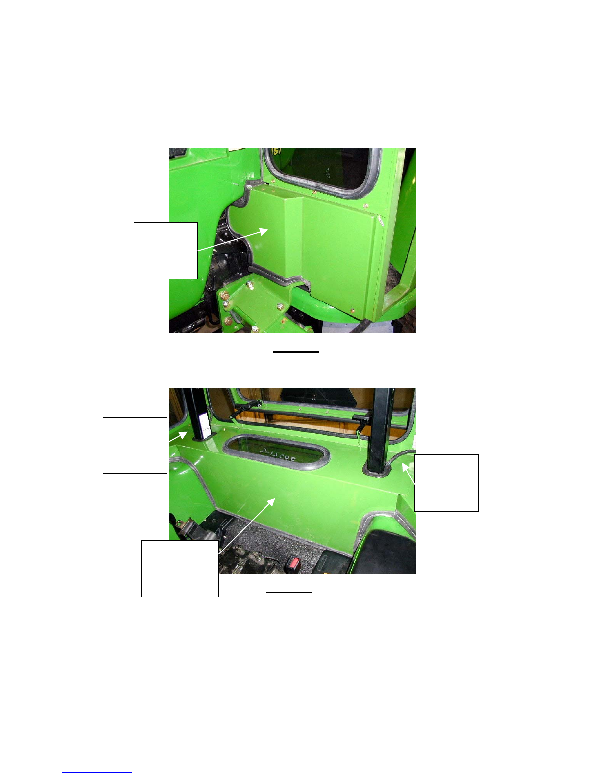
18) Attach front left and right foot pockets using (8) #10-24 x 5/8” bolts (See Figure 5).
RIGHT
OVERLAP
PANEL
#4-14418
CENTER
REAR SEAL
PANEL
#4-14417
Figure 6
LEFT
OVERLAP
PANEL
#4-14419
19) Install rear overlaps, left #4-14419, right #4-14418 panel and rear center seal panel
#4-14417. Secure using (6) #10-24 x 5/8” bolts. See Figure 6.
05-10357
June 2003
Page 7
John Deere 4500, 4510, 4600, 4610, 4700 & 4710
(
)
Page 7 of 29
CAB MOUNTING INSTRUCTIONS (Continued)
Electrical Hookup
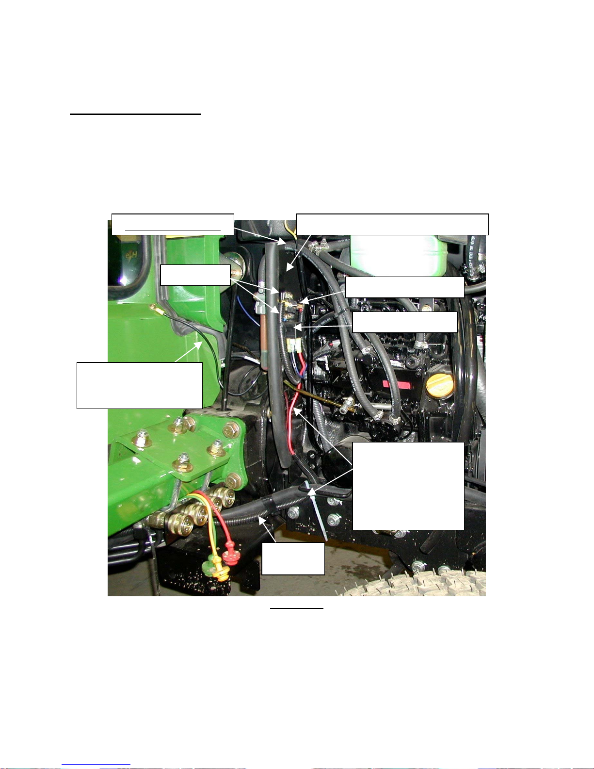
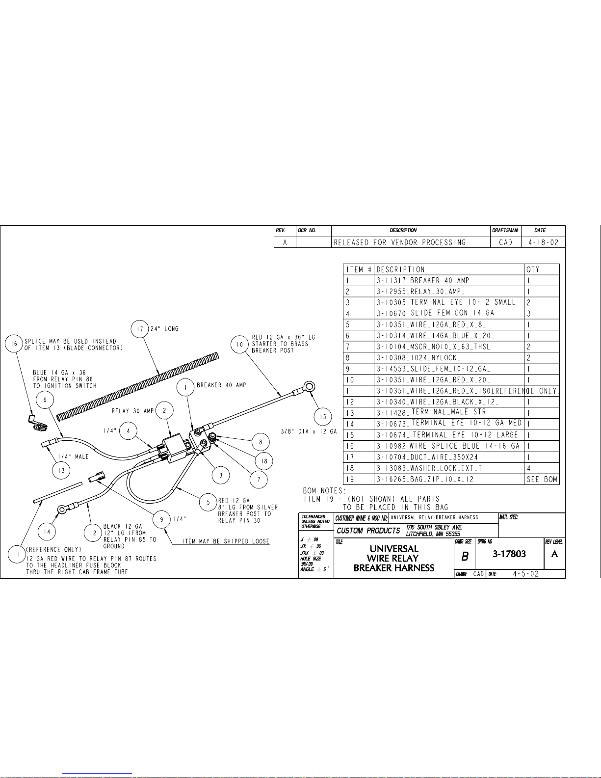
20) Locate the wire relay breaker harness #3-17803 that comes with the mount kit.
Review Figure 6 for proper location and mounting.
21) If holes are not present, drill two ¼” holes. Use the (2) #10 x 5/8” machine screws,
washers and nuts, from the wire relay breaker harness to attach these
components.
OIL LEVEL STICK
NOTE 20
NOTE 22 -GROUND
WIRE #8-14258
CAB TO FRAME
JD FACTORY MOUNT BRACKET
40 AMP BREAKER
30 AMP RELAY
RED 12 GA WIRE
FROM RELAY
PIN 87 TO CAB
HEADLINER
FUSE BLOCK
Note 22
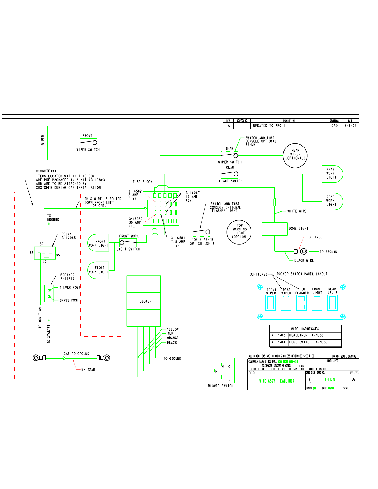
22) Refer to drawings #3-17803 and #8-14376 for additional electrical detail.
23) The main power wire to the headliner fuse block should be pre-routed from the
factory, down the right side of the cab frame.
24) Connect the Cab to Frame Grounding Wire Assembly #8-14258.
WIRE
LOOM
FIGURE 6
05-10357
June 2003
Page 8
John Deere 4500, 4510, 4600, 4610, 4700 and 4710
Page 8 of 29
MOUNTING INSTRUCTIONS (Continued)
THERMOSTAT
Heater Hook-Up
NOTE 26
(PRESSURE)
25) Drain coolant from radiator and engine
block.
26) Use thread sealant on all pipe threads.
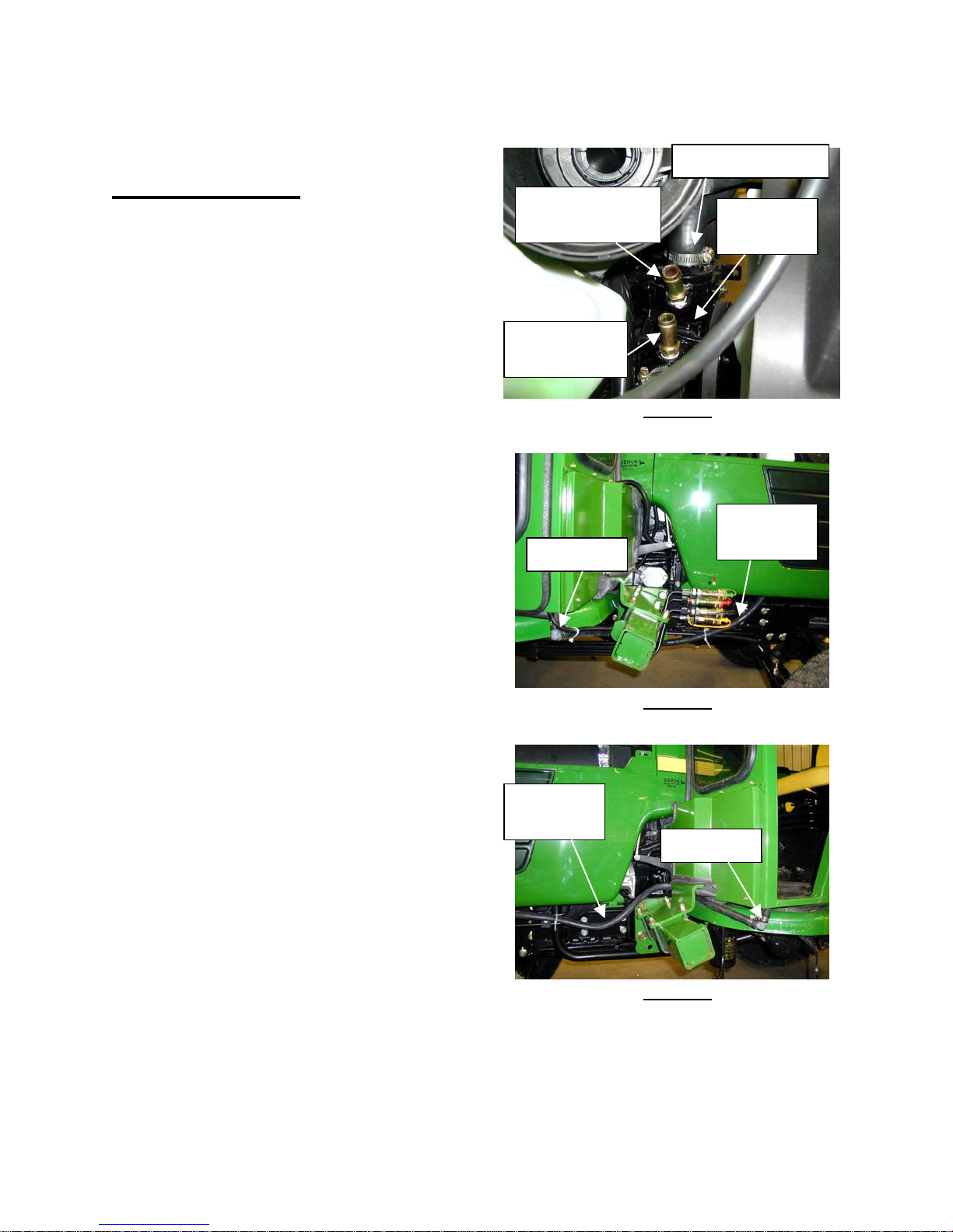
27) Locate the top pipe plug on the water
pump near the engine’s thermostat.
Remove the plug.
28) On models; (See Figure 7).
NOTE 28
(RETURN)
*4510, 4610 and 4710
-Install (1) #3-17756, 3/8-19 BSPT to
Figure 7
5/8” hose nipple.
*4500, 4600 and 4700
-Install (1) #3-12119, 3/8-18 NPT to
5/8” hose nipple.
28) Locate where the lower radiator hose
connects to the water pump. Just
above this connection, locate the pipe
ELBOW
plug port and remove the plug.
29) On models; (See Figure 7).
*4510, 4610 and 4710
-Install (1) #3-17757, 3/8-19 BSPT to
5/8” hose nipple.
*4500, 4600 and 4700
-Install (1) #3-12119, 3/8-18 NPT to
Figure 8
5/8” hose nipple.
30) Locate the heater hose, (2) 90-degree
plastic elbows and (6) 5/8” hose clamps
that come with the kit.
31) Install (1) elbow #3-10282, measure
and cut 5/8” heater hose from right side
HOSE
ROUTE
ELBOW
of cab to the hot-pressure nipple on the
top of the water pump, just installed.
See Figure 8.
32) Install (1) elbow #3-10282, measure
and cut heater hose from left side of
cab to the lower radiator return nipple,
just installed. See Figure 9.
Figure 9
33) Tighten all connections using 5/8” hose
clamps supplied with the kit.
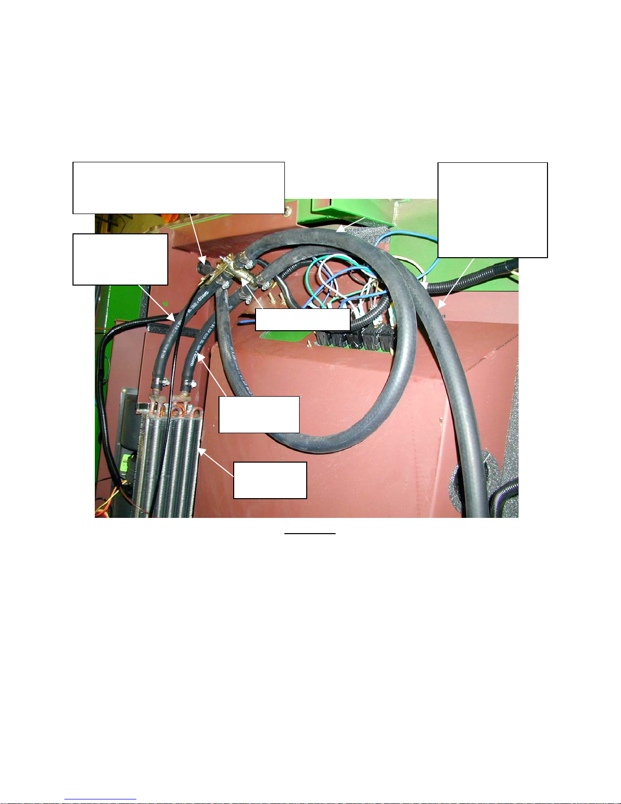
34) To check the “H” Valve and hose routing, remove the roof to inspect the cab’s
headliner heater area. See Figure 10.
WATER
PUMP
HOSE
ROUTE
05-10357
June 2003
Page 9
John Deere 4500, 4510, 4600, 4610, 4700 & 4710
Page 9 of 29
CAB MOUNTING INSTRUCTIONS (Continued)
35) Verify hose routing from water pump nearest the thermostat to the top nipple of the
“H” valve. See Figure 10.
36) Also, check that the return hose from the lower “H” valve nipple is routed to the
lower radiator hose port return nipple.
(HOT) PRESSURE LINE FROM
WATER PUMP ROUTES UP
RIGHT CAB FRAME TO “H” VALVE
HOT
(PRESSURE)
LINE (IN)
RETURN
LINE (OUT)
RETURN LINE
HOSE ROUTES
DOWN LEFT
CAB FRAME TO
WATER PUMP
SUCTION PORT
“H” VALVE
HEATER
CORE
Figure 10
37) Refill radiator.
38) Reconnect battery and start engine. Run at fast idle to purge air from system and
check for any leaks. Cycle the heat/pull lever from inside the cab, on and off
several times while engine is running. Check coolant level after heater core and
hoses are filled.
39) Some cab owners may chose to remove the cab for the summer and re-install in
the fall. Keep and store the removed port plugs for re-use.
05-10357
June 2003
Page 10

MOUNTING INSTRUCTIONS ADDENDUM
Page 10 of 29
John Deere 4500, 4510, 4600, 4610, 4700 and 4710
A. REAR WARNING LIGHTS MOUNTING (INSTRUCTION)
The mount kit comes with 2 dual or single light mounting brackets. Part numbers 715661 AND 7-15662.
Use these brackets when remounting lights onto cab. Use (4) M8 x 25 mm cap screws
(Part Number 3-10123), 5/16” lock washers to secure bracket. Install light bracket to
cab with ¼-20unc x ¾” screws (Part number 3-10219), lock-washers and flat washers to
secure bracket to cab.
B. STEP EXTENSION MOUNTING (INSTRUCTION)
Since the cab is extended beyond the tractor’s factory step, the mount kit comes with a
step extension part number 7-15446. See cover of manual.
The new step extension installs onto the tractor’s factory step. Use back up plate part
number 6-41222 under the factory step and secure with (3) Qty 3-10046 (1/2-13UNC x
1-1/2” long) bolts, (3) ½-13UNC Nylock nuts and (2) ½” flat washers for the slot mount
hole.
C. ROOF OPTIONS, 4500; “00” and “10” Series Models
As of November 2002, cabs will be equipped with a standard folding ROPS roof. The
roof will have a domed shell in the rear part of the roof to allow clearance of the taller
folding ROPS from the interior of the cab. The same folding ROPS roof, fits both “00”
and “10” Series, ROPS and NON-ROPS Models.
D. Exhaust Extension Kit
For applications that require a high exhaust system, over the head of the operator, a
vertical exhaust kit is available through your John Deere dealer. As of this document’s
date, the vertical exhaust kit LVB 25013 may be used on models 4500, 4510, 4600,
4610, 4700 and 4710 series. Verify correct kit number with your John Dear dealer.
05-10357
June 2003
Page 11

John Deere 4500, 4510, 4600, 4610, 4700 & 4710
Page 11 of 29
A-11202 Replacement Parts
ASSEMBLY DRAWINGS
CP PART DESCRIPT ION
8-14383
8-14384
8-14385
8-14386
8-14387
8-14400
8-14417
8-14593
4-14376
3-17803
REPLACEMENT PARTS, ASSEMBLY, CAB
REPLACEMENT PARTS, ASSEMBLY, RIGHT DOOR
REPLACEMENT PARTS, ASSEMBLY, LEFT DOOR
REPLACEMENT PARTS, ASSEMBLY, MOUNT KIT
REPLACEMENT PARTS, ASSEMBLY, HEADLINER
REPLACEMENT PARTS, ASSEMBLY, REAR HINGED WINDOW
REPLACEMENT PARTS, ASSEMBLY, CENTER REAR SEAL
HEATER HOOK UP KIT
WIRING SCHEMATIC
UNIVERSAL WIRE RELAY BREAKER HARNESS
ROOF PARTS REFERENCE
N/A
8-14388
NON-FOLDING ROPS ROOFS
FOLDING ROPS ROOFS
05-10357
June 2003
Page 12

John Deere 4500, 4510, 4600, 4610, 4700 & 4710
Page 12 of 29
A-11202 Replacement Parts
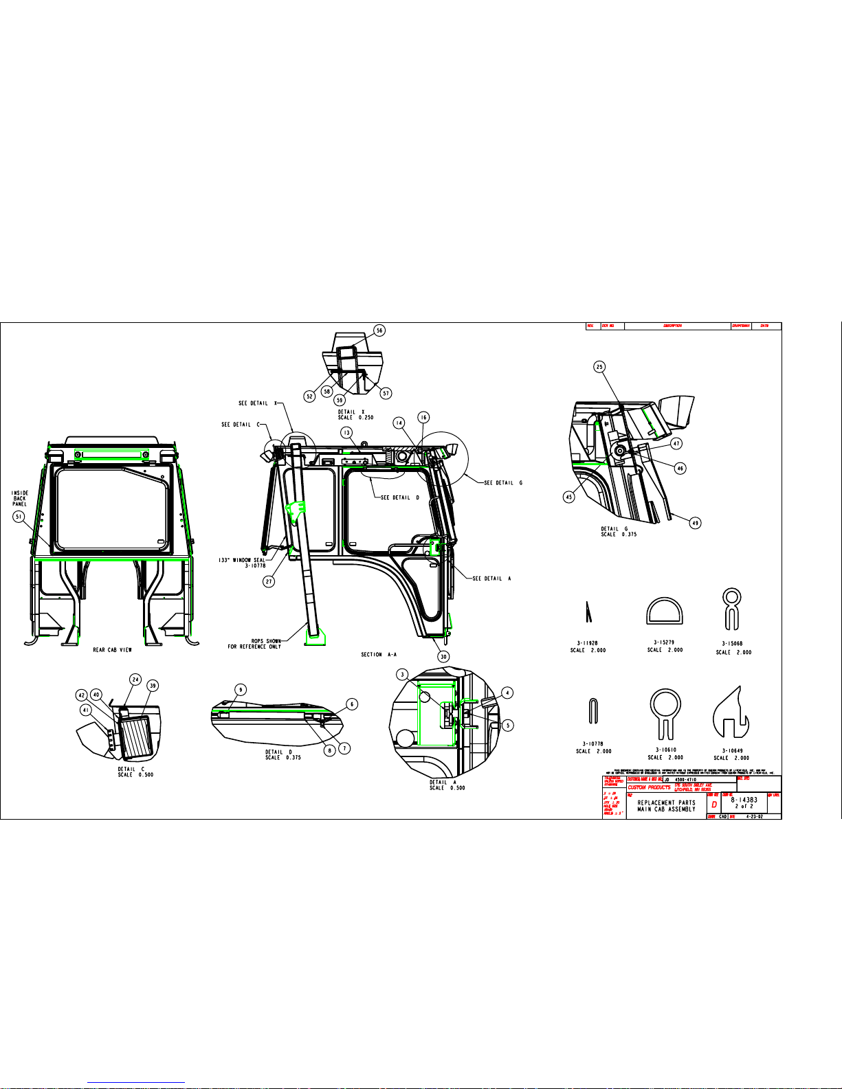
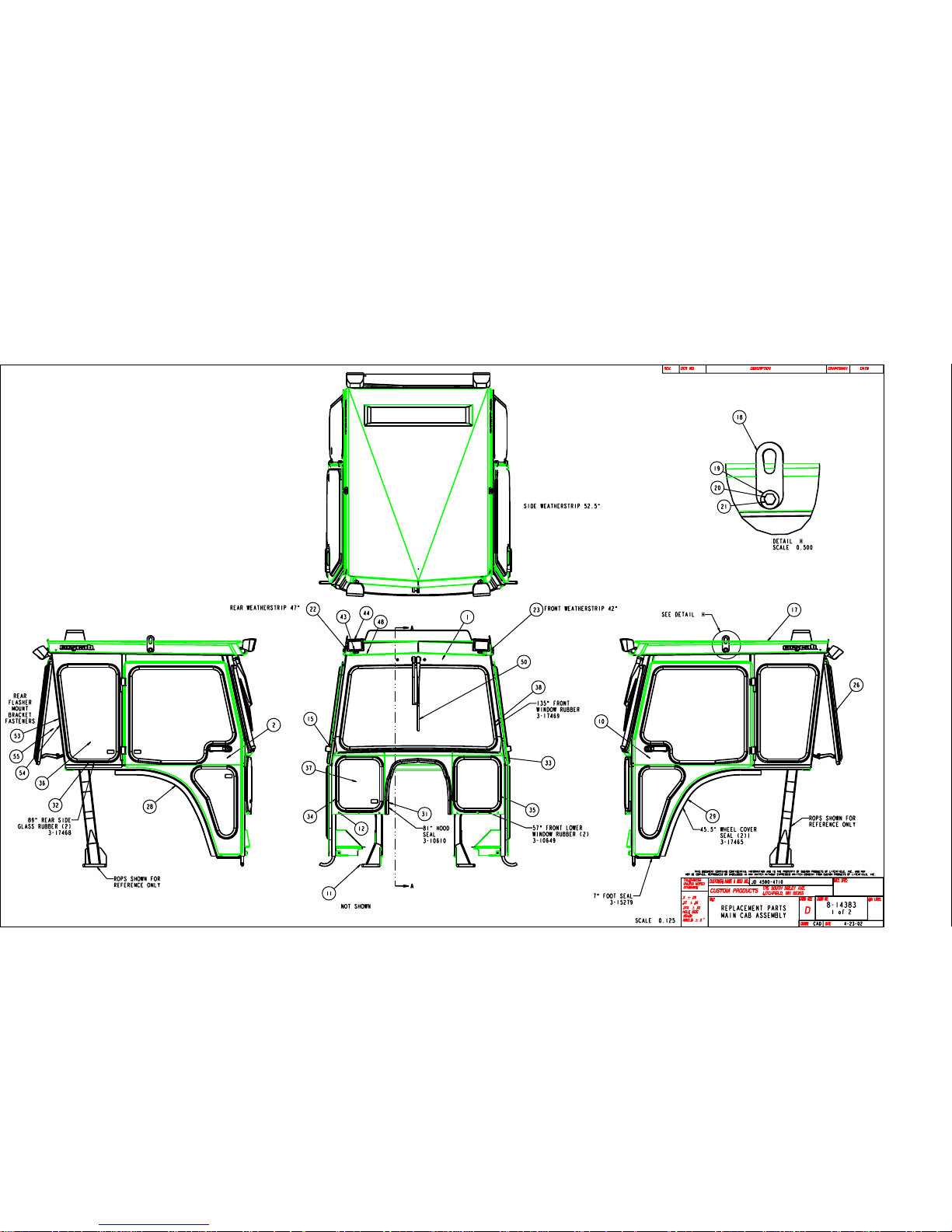
MAIN CAB ASSEMBLY DRAWING 8-14383
DRAWING CUSTOM PROD. ITEM
ITEM NO.
1 7-15367 WELDMENT, MAIN CAB
2 8-14384 ASSEMBLY, RIGHT DOOR
3 3-15407 STRIKER STUD W/WASHER, 7/16-14 NC X 1-1/4" LONG
4 3-10166 WASHER, 7/16" FLAT
5 3-10472 HEX NUT, NYLOCK, 7/16-14 NC
6 3-10077 WASHER, 5/16" FLAT
7 3-11821 BALL STUD, GAS SPRING, 10MM
8 3-13024 GAS SPRING, 20 PSI, 6" STROKE, 10MM ENDS
9 3-11822 CLIP, GAS SPRING, 10MM
10 8-14385 ASSEMBLY, LEFT DOOR
11 8-14386 ASSEMBLY, MOUNT KIT
12 3-16600 NUT-SERT, #10-24 NC
14 3-14387 NUT-SERT, 1/4-20 NC
15 3-10076 WASHER, 1/4" LOCK
16 3-10220 HEX-HEAD BOLT, 1/4-20 NC X 1" LONG, GRD 5
17 8-14388 ASSEMBLY, ROOF FOLDING ROPS (STANDARD)
18 6-20618 LIFTING EAR
19 3-10087 WASHER, 1/2" FLAT
20 3-10079 WASHER, 1/2" LOCK
21 3-10129 HEX-HEAD BOLT, 1/2-13 NC X 1" LONG, GRD 5
22-23 3-11928 WEATHERSTRIP, V-SEAL, 7/8" WIDE, PSA BACK
24 3-15279 RUBBER, D-SEAL, 9/16" HIGH X 3/4" WIDE, PSA BACK
25 3-15068 SEAL RUBBER, 3/8" OD BUBBLE, UP TO 1/8" MATERIAL
26 8-14400 ASSEMBLY, REAR HINGED WINDOW
27 3-10778 TRIM, PINCHWELD, LARGE
28-29 3-17465 SEAL FOAM, 1-1/2" SQUARE EPDM, 45" LONG
30 3-15279 RUBBER, D-SEAL, 9/16" HIGH X 3/4" WIDE, PSA BACK
31 3-10610 SEAL RUBBER, CLIP-ON BUBBLE, 180 DEGREE
32-35 3-10649 WINDOW RUBBER, 1/8" OFFSET, FOR 1/4" THICK GLASS
36 3-17468 GLASS, SIDE REAR (7/32" THICK)
37 3-17469 GLASS, FRONT LOWER (7/32" THICK)
38 3-17470 GLASS, WINDSHIELD (1/8" THICK)
39 3-15944 AIR FILTER, 2-3/16" X 3" X 20-7/8"
40 6-40507 COVER, AIR FILTER
41 3-15573 KNOB, BLACK PLASTIC, 1-3/4" DIA
42 3-11264 POLYFOAM, 1/8" X 5/8", PSA BACK
43 3-10727 GROMMET, SNAP BUSHING, 1/4" DIA MOUNTING HOLE
44 3-15524 FLOOD LIGHT, RECTANGULAR, 12 V
45 3-11099 WIPER MOTOR, 12V, 1" SHAFT, SINGLE SPEED
46 3-10083 WASHER, 3/16" FLAT
47 3-10135 SCREW, #10-24 NC X 1" LONG, TRUSS HEAD, SLOTTED
48 3-10308 HEX NUT, NYLOCK, #10-24
49 3-15776 WIPER ARM, PANTOGRAPHIC, 16" LONG, FOR WWF'S
50 3-15763 WIPER BLADE, 16" FLEX, WIDE
PART NO. DESCRIPTION
05-10357
June 2003
Page 13

John Deere 4500, 4510, 4600, 4610, 4700 & 4710
Page 13 of 29
A-11202 Replacement Parts
MAIN CAB ASSEMBLY DRAWING 8-14383 (Continued)
DRAWING CUSTOM PROD. ITEM
ITEM NO.
51 3-16678 SAFETY DECAL, "CAUTION NOT A ROPS"
52 6-41115 INSULATION, 1/4" HEATHER CHARCOAL, ROPS POCKET
53 3-10219 HEX HEAD BOLT, 1/4-20UNC x 3/4" LG
54 3-10729 GROMMET, SNAP BUSHING, 3/8" DIA x .44" MNTG HOLE
55 3-10123 HEX HEAD BOLT, M8 x 25 METRIC
56 REF FOLDING ROPS (REFERENCE ONLY)
57 3-17929 U-NUT, 10-24UNC CLIP
58 8-14671 ROPS COVER PANEL
59 3-14927 SCREW,FLANGE TYPE NUMBER 10-24UNC x 5/8" LG
PART NO. DESCRIPTION
05-10357
June 2003
Page 14
Page 14 of 29
Page 15
Page 15 of 29
Page 16

John Deere 4500, 4510, 4600, 4610, 4700 & 4710
Page 16 of 29
A-11202 Replacement Parts
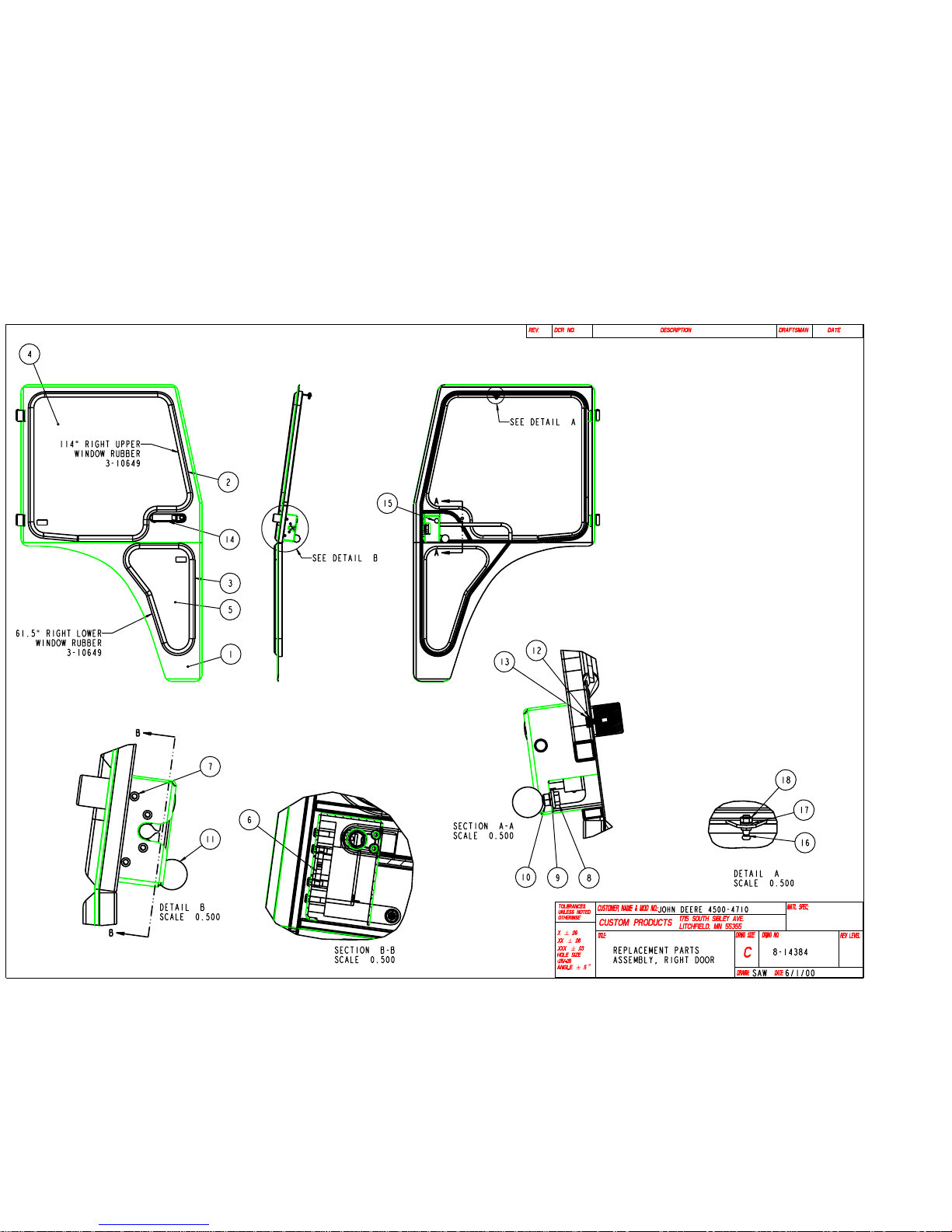
RIGHT DOOR ASSEMBLY DRAWING 8-14384
DRAWING CUSTOM PROD. ITEM
ITEM NO.
1 7-15368 WELDMENT, RIGHT DOOR
2-3 3-10649 WINDOW RUBBER, 1/8" OFFSET, FOR 1/4" THICK GLASS
4 3-17471 GLASS, UPPER DOOR (7/32" THICK)
5 3-17472 GLASS, LOWER DOOR (7/32" THICK)
6 3-15640 ROTARY LATCH, RIGHT HAND (FOR P/B HANDLE)
7 3-10106 SCREW, 1/4-20 NC X 5/8" LONG, BUTTON HEAD, TOREX
8 3-10147 HEX-HEAD BOLT, 3/8-16 NC X 1" LONG, GRD 5
9 3-10078 WASHER, 3/8" LOCK
10 3-10065 HEX NUT, 3/8-16 NC
11 3-14231 KNOB, ROUND, WITH 3/8-16 NC INSERT
12 3-10076 WASHER, 1/4" LOCK
13 3-12692 HEX-HEAD BOLT, M6-15 X 1" LONG, GRD 8.8
14 3-15574 HANDLE, BLACK, PUSH BUTTON
15 3-11741 HOLE PLUG, BLACK PLASTIC, FOR 3/4" DIA HOLE
16 3-11821 BALL STUD, GAS SPRING, 10MM
17 3-10077 WASHER, 5/16" LOCK
18 3-10064 HEX NUT, 5/16-18 NC
PART NO. DESCRIPTION
05-10357
June 2003
Page 17
Page 17 of 29
Page 18

John Deere 4500, 4510, 4600, 4610, 4700 & 4710
Page 18 of 29
A-11202 Replacement Parts
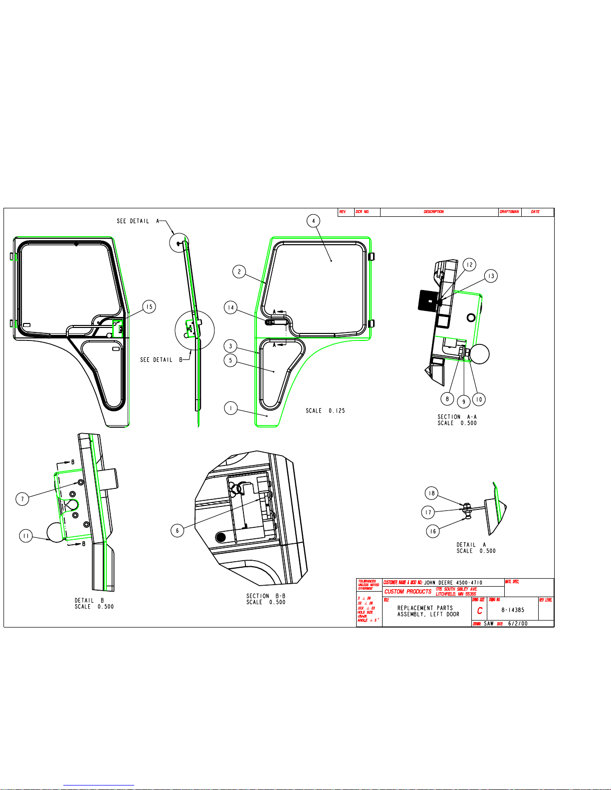
LEFT DOOR ASSEMBLY DRAWING 8-14385
DRAWING CUSTOM PROD. ITEM
ITEM NO.
1 7-15369 WELDMENT, LEFT DOOR
2-3 3-10649 WINDOW RUBBER, 1/8" OFFSET, FOR 1/4" THICK GLASS
4 3-17471 GLASS, UPPER DOOR (7/32" THICK)
5 3-17472 GLASS, LOWER DOOR (7/32" THICK)
6 3-15567 ROTARY LATCH, LEFT HAND (FOR P/B HANDLE)
7 3-10106 SCREW, 1/4-20 NC X 5/8" LONG, BUTTON HEAD, TOREX
8 3-10147 HEX-HEAD BOLT, 3/8-16 NC X 1" LONG, GRD 5
9 3-10078 WASHER, 3/8" LOCK
10 3-10065 HEX NUT, 3/8-16 NC
11 3-14231 KNOB, ROUND, WITH 3/8-16 NC INSERT
12 3-10076 WASHER, 1/4" LOCK
13 3-12692 HEX-HEAD BOLT, M6-15 X 1" LONG, GRD 8.8
14 3-15574 HANDLE, BLACK, PUSH BUTTON
15 3-11741 HOLE PLUG, BLACK PLASTIC, FOR 3/4" DIA HOLE
16 3-11821 BALL STUD, GAS SPRING, 10MM
17 3-10077 WASHER, 5/16" LOCK
18 3-10064 HEX NUT, 5/16-18 NC
PART NO. DESCRIPTION
05-10357
June 2003
Page 19
Page 19 of 29
Page 20

John Deere 4500, 4510, 4600, 4610, 4700 & 4710
Page 20 of 29
A-11202 Replacement Parts
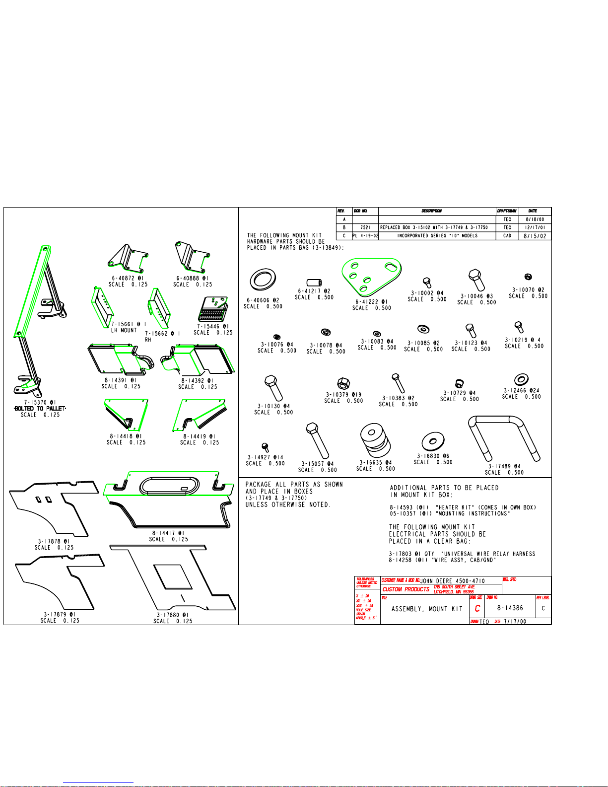
MOUNT KIT DRAWING 8-14386
DRAWING CUS TOM PROD. ITEM
ITEM NO.
1 7-15370 WELDMENT, REAR MOUNT
2 3-16635 RUBBER MOUNT, ISOLATION
3 3-16830 WASHER, 1/2" FLAT, WIDE
4 3-15057 HEX-HEAD BOLT, 1/2-13 NC X 3-1/4" LONG, GRD 5
5 3-10379 HEX NUT, NYLOCK, 1/2-13 NC
6 3-12466 WASHER, 1/2" FLAT
7 3-10130 HEX-HEAD BOLT, 1/2-13 NC X 2" LONG, GRD 5
8 6-40872 RIGHT FRONT MOUNT BRACKET, TRACTOR
9 6-40888 LEFT FRONT MOUNT BRACKET, TRACTOR
10 6-41217 STAND-OFF FOR SMV SIGN
11 6-40606 SPACER, RUBBER MOUNT
12 3-17489 U-BOLT, 1/2-13 NC, 4" WIDE X 5-1/8" LONG
13 8-14391 ASSEMBLY, RIGHT FOOT POCKET
14 8-14392 ASSEMBLY, LEFT FOOT POCKET
15 3-14927 SCREW, #10-24 NC X 5/8" LONG, HEX-HEAD, SERFLING
16 8-14417 ASSEMBLY, CENTER REAR SEAL PANEL
17 8-14418 ASSEMBLY, RIGHT REAR SEAL PANEL
18 8-14419 ASSEMBLY, LEFT REAR SEAL PANEL
19 7-15562 WELDMENT, RIGHT FLASHER GUARD
20 7-15661 WELDMENT, LEFT FLASHER GUARD
21 3-10083 WASHER, 3/16" FLAT
22 3-10076 WASHER, 1/4" LOCK
23 3-10002 HEX-HEAD BOLT, 1/4-20 NC X 5/8" LONG, GRD 5
24 3-10729 GROMMET, SNAP BUSHING, FOR 1/2" DIA MNTG HOLE
25 3-10078 WASHER, 3/8" LOCK
26 3-10123 HEX-HEAD BOLT, M8-25 X 1-1/4" LONG, GRD 8.8
27 3-10085 WASHER, 5/16" FLAT
28 8-14593 HEATER HOOKUP KIT
29 05-10357 INSTRUCTION MANUAL FOR JD 4500-4710 MODELS
30 3-17878 PROTECTIVE MAT RIGHT (6-41211)
31 3-17879 PROTECTIVE MAT LEFT (6-41212)
32 3-17880 PROTECTIVE MAT UNDERSEAT (6-41213)
33 3-17803 UNIVERSAL WIRE RELAY BREAKER HARNESS
34 8-14258 CAB TO FRAME GROUNDING WIRE ASSEMBLY
35 7-15446 STEP EXTENSION
36 6-41222 BACKING PLATE FOR STEP EXTENSION
37 3-13849 BAG (NOT A REPLACEMENT PART)
38 3-10219 HEX HEAD CAP SCREW, 1/4-20UNC x 3/4" LG
39 3-17749 BOX, 17 x 42.75 x 9.75 (NOT A REPLACEMENT PART)
40 3-17750 BOX, 8 x 11.5 x 19 (NOT A REPLACEMENT PART)
41 3-10383 HEX HEAD CAP SCREW, 1/4-20UNC x 1-3/4" LG
42 3-10070 HEX NUT, NYLOCK, 1/2-13 NC
43 3-10046 HEX HEAD CAP SCREW, 1/2-13UNC x 1.5 GR 5
PART NO. DESCRIPTION
05-10357
June 2003
Page 21
Page 21 of 29
Page 22

John Deere 4500, 4510, 4600, 4610, 4700 & 4710
Page 22 of 29
A-11202 Replacement Parts
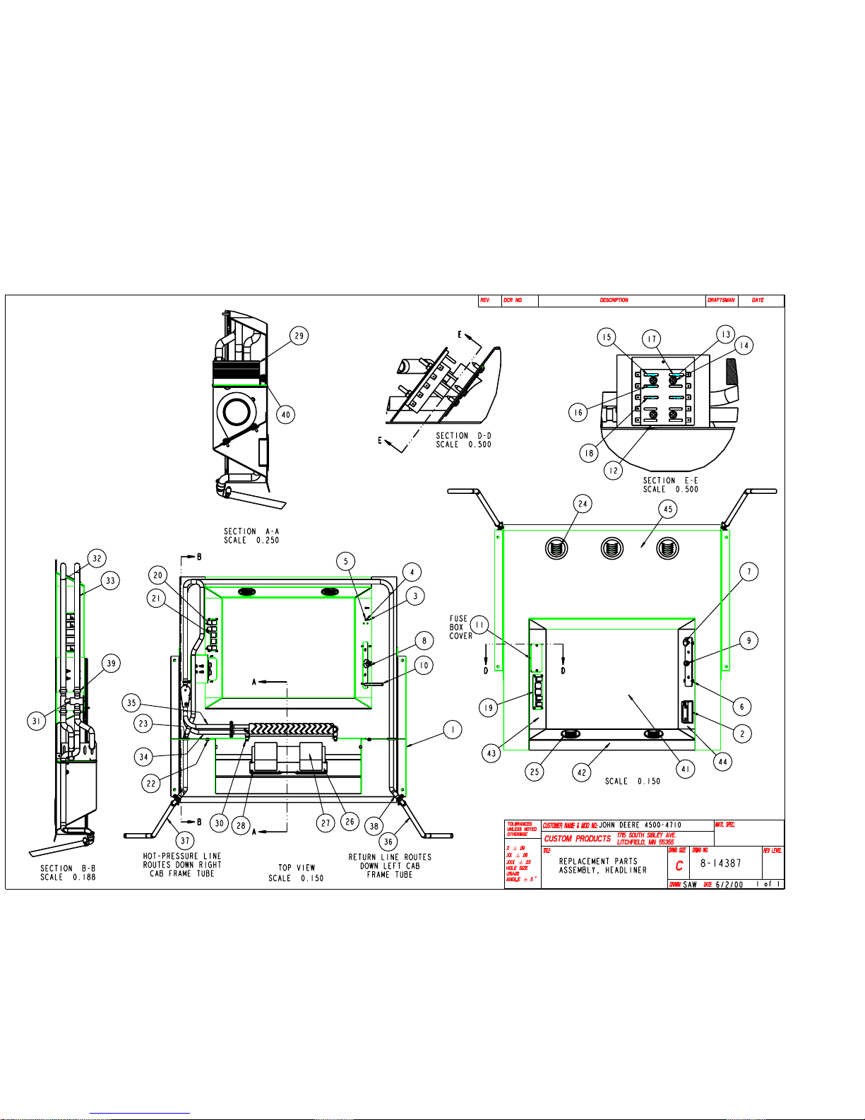
HEADLINER ASSEMBLY DRAWING 8-14387
DRAWING CUSTOM PROD. ITEM
ITEM NO.
1 3-16232 DOMELIGHT, RECTANGULAR, 12V
2 3-16984 SCREW, #6-32 NC X 1-1/2" LONG, ROUND HEAD, SLOTTED
3 3-10088 WASHER, 3/16" LOCK
4 3-12637 HEX NUT, #6-32
5 6-40504 SWITCH PLATE, HEATER/FAN
6 3-11812 SCREW, #10 SELFTAP X 3/4" LONG, PAN HEAD, PHILLIPS
7 3-15432 BLOWER SWITCH, 3-SPEED ROTARY
8 3-11173 KNOB, BLOWER SWITCH
9 3-11149 CABLE ASSEMBLY, HEATER CONTROL, WITH PULL KNOB
10 6-40505 COVER PLATE, FUSE BLOCK
11 3-15926 FUSE BLOCK, 10 CIRCUIT, FOR ATO/ATC FUSES
12 3-10099 SCREW, #10-24 NC X 1-1/2" LONG, ROUND HEAD, SLOT
13 3-10308 HEX NUT, NYLOCK, #10-24 NC
14 3-16580 FUSE, ATO/ATC, 30 AMP
15 3-16581 FUSE, ATO/ATC, 7-1/2 AMP
16 3-16582 FUSE, ATO/ATC, 2 AMP
17 3-16057 FUSE, ATO/ATC, 10 AMP
18 6-40506 SWITCH PLATE, WIPER/LIGHTS
19 3-16274 ROCKER SWITCH, ON/OFF
20 3-16677 PLUG, ROCKER SWITCH HOLE
21 3-10729 GROMMET, SNAP BUSHING, FOR 1/2" DIA MNTG HOLE
22 3-10730 GROMMET, SNAP BUSHING, FOR 1-3/8" DIA MNTG HOLE
23 3-11741 HOLE PLUG, BLACK PLASTIC, FOR 3/4" DIA HOLE
24 3-15594 LOUVER, BLACK ROUND ,FIT 3-3/64" DIA HOLE, ADJ
25 3-15928 LOUVER, BLACK ROUND ,FIT 3-3/64" DIA HOLE, FIXED
26 3-11202 GASKET, SQUARE BLOWER
27 3-15935 BLOWER, DUAL WHEEL, 12 VOLT, 235 CFM
28 3-10105 SCREW, #10-24 NC X 3/4" LONG, TRUSS HEAD, PHILLIPS
29 3-16572 HEATER CORE, 5/8" DIA HOSE FITTINGS
30 3-16672 MOUNTING CLIP, HEATER CORE
31 3-16692 VALVE, HEATER CONTROL, 5/8" DIA HOSE FITTINGS
32-37 3-11172 HEATER HOSE, 5/8" INSIDE DIA
38 3-10282 PLASTIC ELBOW, FOR 5/8" DIA HOSE, 90 DEGREE
39 3-10858 HOSE CLAMP, #10 SCREW, RANGE DIA 9/16" TO 1-1/16"
40 3-17319 RUBBER, D-SEAL, 3/4" HIGH X 3/4" WIDE, PSA BACK
41 6-41110 INSULATION, 1/4" HEATHER CHARCOAL, CENTER
42 6-41111 INSULATION, 1/4" HEATHER CHARCOAL, REAR
43 6-41112 INSULATION, 1/4" HEATHER CHARCOAL, RIGHT SIDE
44 6-41113 INSULATION, 1/4" HEATHER CHARCOAL, LEFT SIDE
45 6-41114 INSULATION, 1/4" HEATHER CHARCOAL, FRONT
PART NO. DESCRIPTION
05-10357
June 2003
Page 23
Page 23 of 29
Page 24

John Deere 4500, 4510, 4600, 4610, 4700 & 4710
Page 24 of 29
A-11202 Replacement Parts
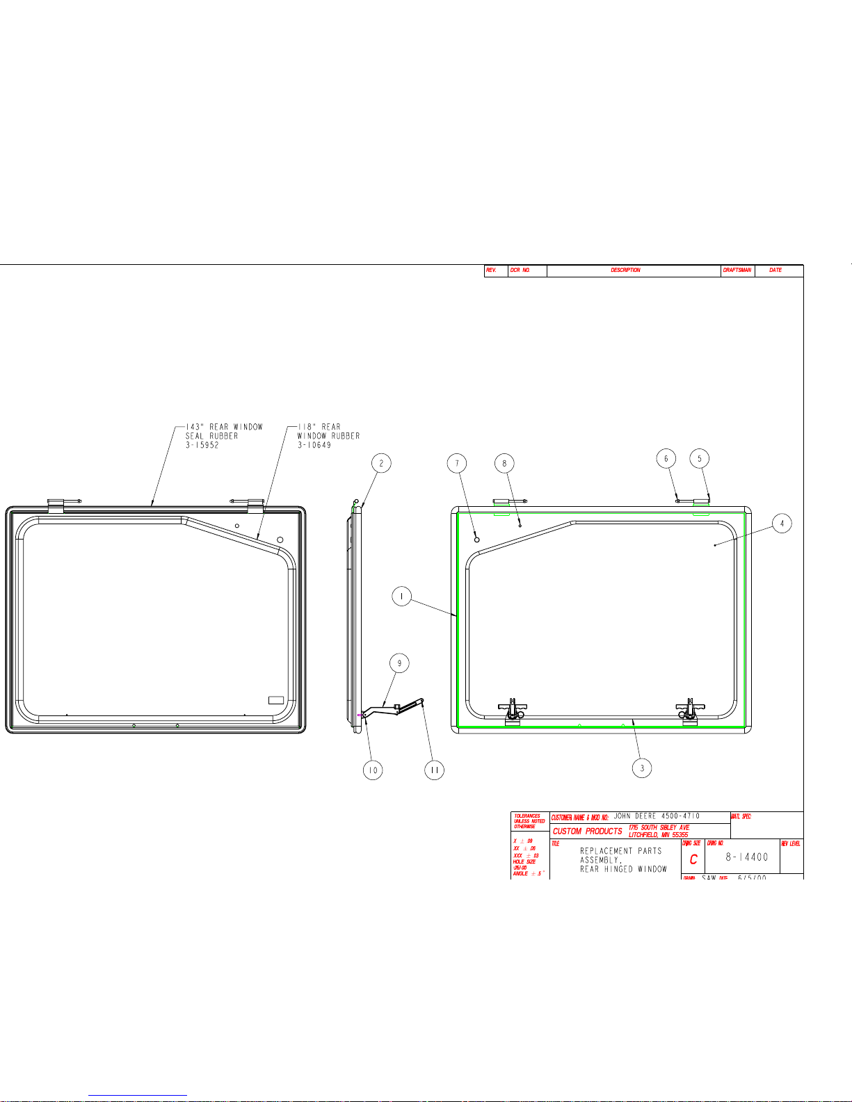
REAR HINGED WINDOW ASSEMBLY DRAWING 8-14400
ITEM NO. PART NO. DESCRIPTION
1 7-15396 WELDMENT, REAR HINGED WINDOW
2 3-15952 SEAL RUBBER, 3/4" OD BUBBLE, UP TO 1/8" MATERIAL
3 3-10649 WINDOW RUBBER, 1/8" OFFSET, FOR 1/4" THICK GLASS
4 3-17485 GLASS, REAR HINGED WINDOW (7/32" THICK)
5 3-13931 HEX-HEAD BOLT, 1/4-20 NC X 4-1/2" LONG, GRD 5
6 3-10070 HEX NUT, NYLOCK, 1/4-20 NC
7 3-15234 HOLE PLUG, BLACK PLASTIC, FOR 11/16" DIA HOLE
8 3-10721 HOLE PLUG, BLACK PLASTIC, FOR 3/8" DIA HOLE
9 3-16831 T-HANDLE LATCH, BLACK PLASTIC
10 3-16832 PIN, QUICK RELEASE, 3/16" DIA X 1" LONG
11 3-15576 ROLL PIN, T-HANDLE, 3/16" DIA X 1/2" LONG
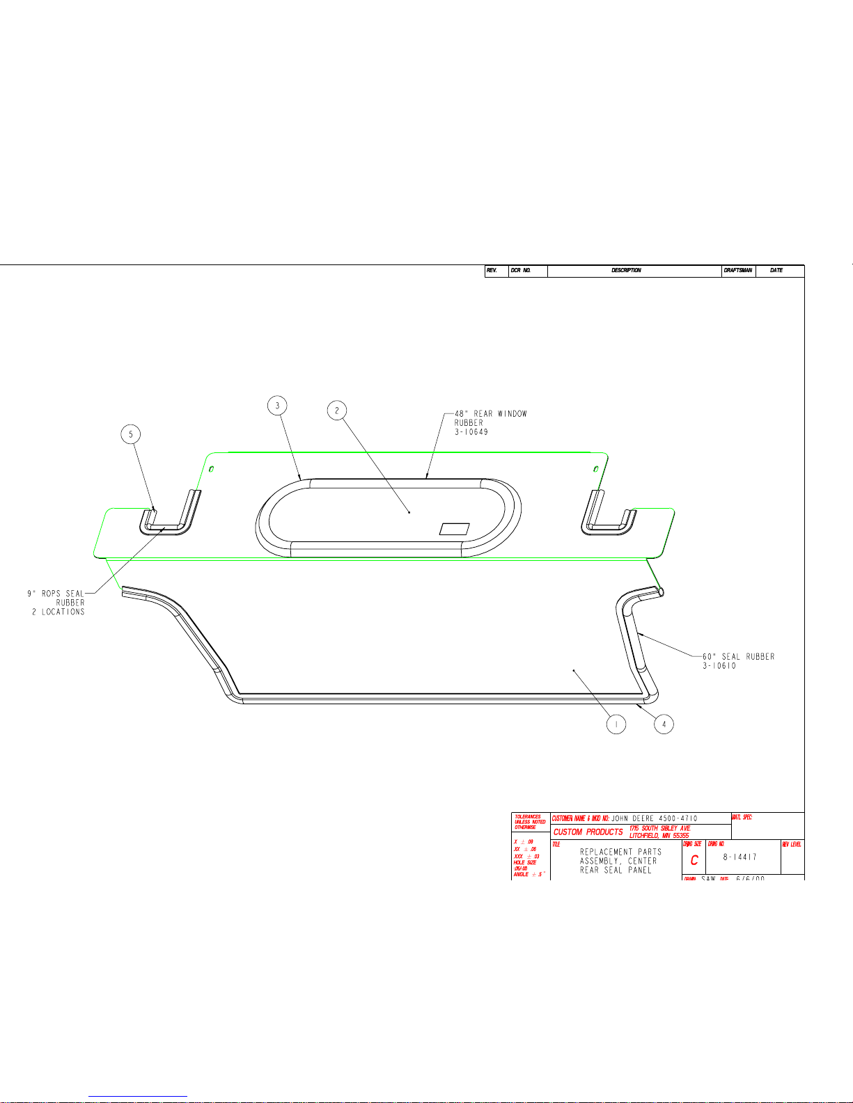
CENTER REAR SEAL PANEL DRAWING 8-14417
ITEM NO. PART NO. DESCRIPTION
1 6-41087 CENTER REAR SEAL PANEL
2 3-17506 GLASS, REAR SEAL PANEL (7/32" THICK)
3 3-10649 WINDOW RUBBER, 1/8" OFFSET, FOR 1/4" THICK GLASS
4 3-10610 SEAL RUBBER, CLIP-ON BUBBLE, 180 DEGREE
5 3-15068 TRIM SEAL, 3/8" BUBBLE, 180 DEGREE
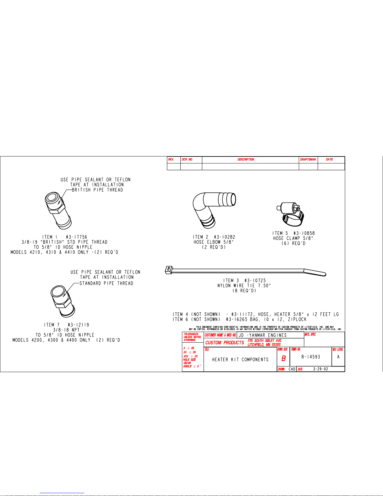
HEATER HOOK UP COMPONENTS DRAWING 8-14593
ITEM NO. PART NO. DESCRIPTION
1 3-17756 FITTING, 3/8-19 BSPT TO 5/8" HOSE NIPPLE
2 3-10282 HOSE ELBOW, 5/8" ID x 90 DEGREE PLASTIC
3 3-10725 NYLON WIRE TIE, 7.50" LG
4 3-11172 HOSE, HEATER 5/8" ID
5 3-10858 HOSE CLAMP 5/8" NUMBER 10
6 3-16265 BAG 10x12, ZIP LOCK (PACKAGING)
7 3-12119 FITTING, 3/8-18 NPT TO 5/8" HOSE NIPPLE
05-10357
June 2003
Page 25
Page 25 of 29
Page 26
Page 26 of 29
Page 27
Page 27 of 29
Page 28
Page 28 of 29
Page 29
Page 29 of 29
 Loading...