

Page 1

DIRECT VENT
WALL FURNACE
INSTALLATION AND
OPERATING INSTRUCTIONS
P/N 70905
REV. 06/2015
MODEL NUMBERS
NA TURAL GAS CDV155C CDV255C CDV335C
L.P . GAS CDV156C CDV256C CDV336C
W ARNING: If the information in these instructions ar e
not followed exactly, a fir e or explosion may result
causing property damage, personal injury or death.
- Do not store or use gasoline or other flammable
vapors and liquids in the vicinity of this or any
other appliance.
- WHA T TO DO IF YOU SMELL GAS:
Do not try to light any appliance.
Do not touch any electrical switch; do not use any
phone in your building.
Immediately call your gas supplier from a neighbor’ s
phone. Follow the gas supplier’s instructions.
If you cannot reach your gas supplier, call the fire
department.
- INST ALLATION AND SERVICE MUST BE
PERFORMED BY A QUALIFIED INST ALLER,
SERVICE AGENCY OR THE GAS SUPPLIER.
The appliance may be installed in an aftermarket permanently located, manufactured home (USA only)
or mobile home, where not prohibited by local codes. This appliance is only for use with the type of
gas indicated on the rating plate. This appliance is not convertible for use with other gases, unless a
certified kit is used.
WARNING: Operation of this furnace without the properly installed, furnished vent system and vent
cap could result in Carbon Monoxide (CO) poisoning and possible death. For your safety, this furnace
and the vent system should be inspected at least annually by a qualified service technician.
CDV25/
CDV33-C
INST ALLER: Leave this manual with the
appliance.
CONSUMER: Retain this manual for
future reference.
The coating selected to provide longer life to
the heat exchanger may smoke slightly upon
initial firing. Please provide adequate
ventilation if this occurs.
CDV15-C
This unit is for residential use only and is not approved for installation in greenhouses, or environments
involving dusty, wet, corrosive, or explosive conditions. Such conditions will invalidate the warranty and
may create unsafe conditions.
Installation, maintenance, service, trouble shooting and repairs must be performed by a qualified service agency .
Mr./Mrs. Homeowner , DO NOT attempt any of these procedures yourself as this could expose you to property
damage, personal injury , or loss of life and will invalidate all warranties.
Page 2
The State of Massachusetts r equires that installation and service of a gas appliance be
performed by a plumber or gas fitter licensed in the Commonwealth of Massachusetts.
CONTENTS
Introduction……………………………. 2
Specifications and Dimensions…………. 2
Safety Rules……………………………. 2/3
Clearances……………………………… 3/4
Location……………………………….. 5
Installation………………………………. 5 - 8
Vent Kits.................................................. 5 - 7
Gas Connection....................................... 8
BBSK Instructions................................... 12/13
Lighting Instructions…………………… 9
Pilot Adjustment……………………….. 10
Burner Orifice…………………………… 10
Wiring Diagram………………………… 10
Removing Main Burner………………… 10
Proper Burner Flame…………………… 11
Thermostat Installation………………… 11
Installing Optional Blower Kit………… 1 1
Maintenance Instructions......................... 19
Trouble Shooting………………………. 18
Parts Drawing………………………….. 14//16
Parts List……………………………….. 15 /17
Warranty……………………………….. 21
INTRODUCTION
THIS IS A GAS-FIRED, DIRECT VENT WALL FURNACE THAT WILL OPERATE SAFELY AND
PROVIDE AN EFFICIENT SOURCE OF HEAT WHEN INSTALLED, OPERATED AND
MAINTAINED AS RECOMMENDED IN THESE INSTALLATION AND OPERATING
INSTRUCTIONS. READ THESE INSTRUCTIONS THOROUGHLY BEFORE INSTALLING,
SERVICING, OR USING THE APPLIANCE. IF YOU DO NOT UNDERSTAND ANY PART OF
THESE INSTRUCTIONS CONSULT LOCAL AUTHORITIES, OTHER QUALIFIED INSTALLERS,
SER VICE TECHNICIAN, THE GAS SUPPLIER OR THE MANUF ACTURER.
SPECIFICATIONS AND DIMENSIONS
Your Direct Vent Wall Furnace is shipped complete in one carton. This carton contains the furnace, vent
cap, vent tube, air inlet tube, template with rough-in dimensions, installation and operating instructions, and
the thermostat with thermostat wire. NOTE: There will be two cartons if optional vent kit or blower is purchased.
MODEL INPUT GAS TYPE MAX. WALL MIN. WALL
NO. BTU/HR. WIDTH DEPTH HEIGHT CONN. GAS THICKNESS THICKNESS
CDV155C 15,000 18” 9-3/4” 29-3/4” ½” NAT. 24” 5”
CDV156C 15,000 18” 9-3/4” 29-3/4” ½” L.P. 24” 5”
CDV255C 25,000 34-1/2” 9-3/4” 31-3/4” ½” NAT. 24” 5”
CDV256C 25,000 34-1/2” 9-3/4” 31-3/4” ½” L.P. 24” 5”
CDV335C 33,000 34-1/2” 9-3/4” 31-3/4” ½” NAT. 15” 5”
CDV336C 33,000 34-1/2” 9-3/4” 31-3/4” ½” L.P. 15” 5”
SAFETY RULES
1. Improper installation, adjustment, alteration, service, or maintenance can cause property damage, bodily injury, or death.
2. Use in other than a residential application may result in unsatisfactory performance and may void the warranty.
3 . This appliance must be installed in accordance with local codes, if any; if not, follow the National Fuel Gas Code ANSI
Z223.1/NFP A 54 or the National Gas and Propane Installation Code CSA-B149.1.
4 . Do not install this wall furnace in a recreational vehicle or trailer.
5. Do not operate wall furnace unless it is connected to the factory supplied vent system with vent cap in place.
6. Check the rating label attached to the wall furnace to be sure it is equipped for the type gas you intend to use.
7 . Never use a match, candle, flame or other source of ignition to check for gas leaks. Use only soapy water or liquid detergent.
8. Have your wall furnace and vent system inspected at least annually by a qualified service technician.
Page 2
Page 3
SAFETY RULES - CONT’D.
9 . Before cleaning or servicing, turn off the gas and allow furnace to cool.
10.
Do not operate wall furnace without outer casing in place.
Due to high temperatures, the wall furnace should be located out of traffic and away from furniture and drapes.
11.
12.
Children and adults should be alerted to the hazard of high surface temperature and should be kept away to avoid burns or
clothing ignition.
13.
Young children should be carefully supervised when they are in the same room with the wall furnace.
Do not place clothing or other flammable material on or near the furnace.
14.
15.
Installation and repair should be done by a qualified service technician. The wall furnace should be inspected before use
and at least annually by a professional service technician. More frequent cleaning may be required due to excessive lint
from carpeting, bedding material, etc. It is imperative that control compartments, burner, and circulating air passageways of
the furnace be kept clean.
16. Do not install in a closet, alcove, or small hallway where the furnace could be isolated from the space to be heated by
closing a door.
17. Do not put anything around the furnace or vent cap that will obstruct the flow of combustion and ventilation air.
18. The appliance, when installed, must be electrically grounded in accordance with local codes or, in the absence of local
codes, with the latest edition of National Electrical Code, ANSI/NFPA 70. In Canada, use CSA C22.1 Canadian
Electrical Code.
19. Never operate this furnace without the sight glass in place or with the glass broken or missing.
20. If it is suspected that rising water may enter the furnace, turn off the gas immediately. Do not use this appliance if any part
has been under water. Immediately call a qualified service technician to inspect the appliance and to replace any part of the
control system and any gas control which has been under water.
21. It is necessary to replace damaged gaskets or sealing material within the vent or air intake system. Failure to do so may
result in property damage, personal injury or loss of life.
22.
Any safety screen or guard removed for servicing must be replaced prior to operating heater.
23. A gas appliance must not be connected to a chimney flue serving a separate solid-fuel burning appliance.
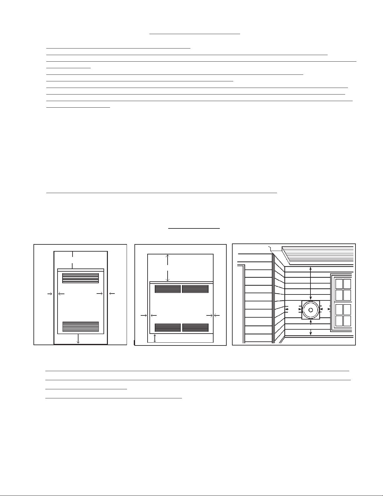
CLEARANCES
CDV15-C CDV25 / CDV33-C ALL VENT CAPS
CEILING
24”
1”
LEFT SIDE WALL
1/2”
FLOOR
FIGURE 1
1.
If the wall furnace is installed directly on carpeting, tile or any combustible material other than wood flooring,
1”
LEFT SIDE WALL
RIGHT SIDE WALL
FIGURE 2
CEILING
30”
1” 0”
4”
FLOOR
RIGHT SIDE WALL
FIGURE 3
12”
Min.
18” Min.
9”
Min.
12” Min.
the wall furnace shall be installed on a metal plate or wood panel secured to the floor, extending the full width
and depth of the wall furnace.
2. RESIDENTIAL GARAGE INSTALLATION: Gas utilization equipment in residential garages shall
be installed so that all burners and burner ignition devices are located not less than 18 inches (46cm)
above the floor . Such equipment shall be located, or protected so it is not subject to damage by a
moving vehicle. Use care in selecting a good location within the garage. DO NOT locate the appliance
where heated air will be directed onto a nearby parked vehicle. Paint may discolor or rubber may
harden and crack. DO NOT allow heated discharge air to blow directly onto open or closed containers
of paint, gasoline or other liquids having flammable vapors.
Page 3
Page 4
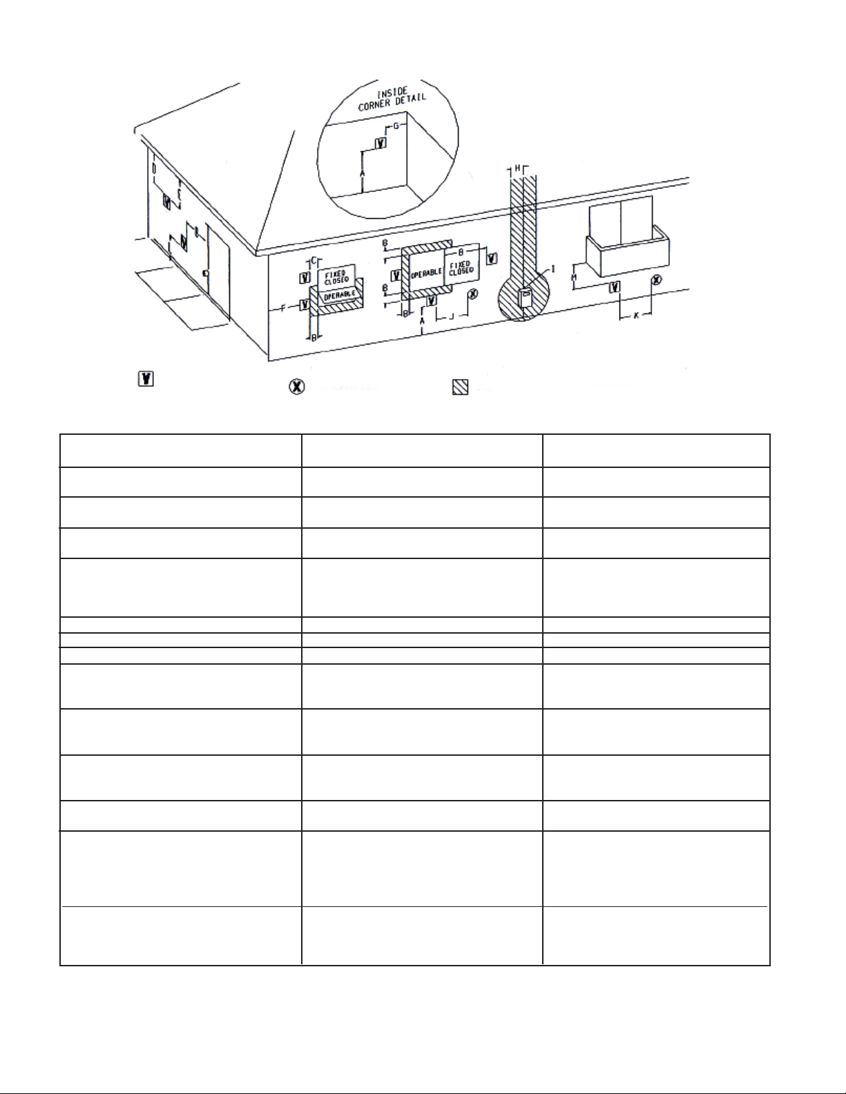
V ent T erminal
Air Supply Inlet
Area where terminal is not permitted
VENT TERMINAL CLEARANCES
REFERENCE LETTER TO DRA WING CANADIAN INST ALLATIONS U.S. INSTALLA TIONS
1
2
A = Clearance above grade, veranda, 12 Inches (30 cm) 12 Inches (30 cm)
porch, deck, or balcony
B = Clearance to window or door that 12 Inches (30 cm) 9 Inches (23 cm)
may be opened
C = Clearance to permanently closed 12 Inches (30 cm) 9 Inches (23 cm)
window
D = V ertical clearance to ventilated sof fit 1 8 Inches (46 cm) 18 Inches (46 cm)
located above the terminal within a
horizontal distance of 2 Feet (61 cm)
from the center line of the terminal
E = Clearance to unventilated soffit 18 Inches (46 cm) 18 Inches (46 cm)
F = Clearance to outside corner 12 Inches (30 cm) 12 Inches (30 cm)
G = Clearance to inside corner 12 Inches (30 cm) 12 Inches (30 cm)
H = Clearance to each side of center line 3 Feet (91 cm) within a height Clearance in accordance with
extended above meter/regulator 15 Feet (4.5m) above the meter/ local installation codes and the
assembly regulator assembly requirements of the gas supplier
I = Clearance to service regulator 3 Feet (91 cm) Clearance in accordance with
vent outlet local installation codes and the
requirements of the gas supplier
J = Clearance to nonmechanical air supply 12 Inches (30 cm) 12 Inches (30 cm)
inlet to building or the combustion
air inlet to any other appliance
K = Clearance to a mechanical air supply 6 Feet (1.83 m) 3 Feet (91 cm) above if within
inlet 10 Feet (3 m) horizontally
L = Clearance above paved sidewalk or 7 Feet (2.13m) A vent shall not Clearance in accordance with
paved driveway located on public terminate directly above a sidewalk or local installation codes and the
property paved driveway that is located between requirements of the gas supplier
two single family dwellings and
serves both dwellings
M = Clearance under veranda, porch, 12 Inches (30 cm) permitted only if Clearance in accordance with
deck, or balcony veranda, porch, deck, or balcony is local installation codes and the
fully open on a minimum of two sides requirements of the gas supplier
1
In accordance with the current CSA-B149.1 Natural Gas and Propane Installation Code
2
In aaccordance with the current ANSI Z223.1 / NFPA 54 National Fuel Gas Code
Page 4
Page 5
LOCATION
1) The wall furnace must be installed on an outside wall.
2) For optimal heat distribution, locate furnace as centrally as possible in the area to be heated and where occupants may move
about freely without coming into contact with the grille.
3) If the furnace is installed in a basement, a 12” clearance must be maintained between ground level and the bottom of the
vent cap. Do not install furnace where vent cap will terminate in a window well or any other opening below ground level.
INSTALLATION
Failure to follow these instructions carefully could result in poor performance, property damage, personal
injury or death.
STEP 1. LOCATE VENT OPENING. Locate wall studs and center 9” vent opening a minimum of 22”
for CDV15 or 24-1/8” for CDV25/33 above the floor. To locate furnace at minimum clearance from floor, remove template from
carton and set on floor at location desired. On model CDV15, position template no closer than 1” from either side wall. For
model CDV25/33, position template 1” minimum from a left side wall or 0” from a right side wall. Check outside wall to be sure
there is proper clearances around the vent cap. See Figure 3. Next, mark and cut out the vent openings on both the inside and
outside walls (be sure to keep the holes level). See Figure 5. If a higher location on the wall is desired, raise bottom of template
to desired height, make sure template is level and centered between studs, mark and cut out vent openings.
STEP 2. ROUGH-IN GAS SUPPLY . Install a ½” diameter gas supply line. This line can enter through the
floor, side, or rear wall. For location of gas connection to valve, see Fig. 4. The gas supply line must have an individual manual
shut off valve located outside the cabinet, accessible from the room where the heater is installed. Install a drip leg immediately
ahead of the gas valve and provide a 1/8” N.P.T. plugged tapping, accessible for test gauge connection, immediately upstream of
the gas supply connection. The furnace and the individual shut off valve must be disconnected from the gas supply piping system
during any pressure testing of that system at test pressures in excess of 1/2” psig (3.5kPa). The furnace must be isolated from the
gas supply piping system by closing the individual manual shut off valve during any pressure testing of the gas piping system at
test pressures equal to or less than 1/2” psig (3.5kPa).
STEP 3. INSTALLING FURNACE – 5” TO 9” WALLS. Use only the exhaust tube, air intake
tube, wall thimble extension, and vent terminal provided with furnace. Do not attempt to lengthen the exhaust or air intake tubes,
this could cause an imbalance in the furnace resulting in poor performance and pilot outage, see Figure 6. Extend the telescoping
wall thimble extension (surrounding the wall thimble assembly) to approximately 9 inches. Center the wall thimble assembly in
the 9 inch opening and attach to inside wall using eight (8) screws. The wall thimble extension should extend through the
opening and be adjusted so end of wall thimble extension is even with outside wall. Install furnace flush to wall by sliding
exhaust tube and air intake tube through the wall thimble assembly. Secure the furnace to the wall with screws through each of
the four holes in the mounting brackets located on the back of the furnace. These holes are spaced so as to allow the screws to
enter into studs that are on 16 inch centers. On certain types of wall, anchors (not provided) may be required. Slide the vent
terminal onto the exhaust tube and the air intake tube. Secure vent terminal and vent terminal spacer plate to wall providing a
slight downward slope to the vent tubes. This will prevent water from entering. Anchors (not provided) may be required. Caulk
around vent terminal spacer plate with putty provided. See Figure 7. NOTE: Some framing may be necessary to provide a flat
surface for the vent terminal spacer plate to butt against, so rain cannot enter through cut out.
Page 5
Page 6

INSTALLING FURNACE – 9 TO 15” WALLS (CDV15/CDV25-C). For
9” to 15” wall use V ent Kit No. VK1525/9-15-B. Do not attempt to lengthen the exhaust tube, air intake tube, or wall thimble extension
provided with furnace or the VK1525/9-15-B Vent Kit. Disconnect the air intake tube, and the exhaust tube from the back of the
furnace and discard. See Figure 6. Replace with exhaust tube and air intake tube from Kit No. VK1525/9-15-B. Discard the 5”
telescoping wall thimble extension that surrounds the wall thimble assembly. Center the wall thimble assembly in the 9” openin g and
attach to inside wall using eight (8) screws. Install furnace flush to wall by sliding exhaust tube and air intake tube through the wall
thimble assembly. Secure the furnace to the wall with screws through each of the four holes in the mounting brackets located o n the
back of the furnace. These holes are spaced so as to allow the screws to enter into studs that are on 16-inch centers. On certain
types of wall, anchors (not provided) may be required. From outside the building install the thick wall thimble extension, Part No.
43835, supplied in V ent Kit No. VK1525/9-15-B by sliding it through the cut out and over the wall thimble assembly . The wall thimble
extension should be even with the outside wall (some trimming may be necessary). Slide the vent terminal onto the exhaust tube and
the air intake tube. Secure vent terminal and vent terminal spacer plate to wall providing a slight downward slope to the vent tubes.
This will prevent water from entering. Anchors (not provided) may be required. Caulk around the vent terminal spacer plate with
putty provided. See Figure 7. NOTE: Some framing may be necessary to provide a flat surface for the vent terminal spacer plate to
butt against, so rain cannot enter through cut out.
INSTALLING FURNACE – 15” TO 24” WALLS (CDV15/CDV25-C).
For 15” to 24” wall use only V ent Kit No. VK1525/15-24-B. Do not attempt to lengthen the exhaust tube, air intake tube, or wall thimble
extension provided with furnace. The VK1525/15-24-B Vent Kit has a one inch restrictor in the exhaust tube which is necessary for
proper and safe operation of this furnace. Do not use any other vent kit. Disconnect the air intake tube and the exhaust tube from
the back of the furnace and discard, see Figure 6. Install the exhaust tube and air intake tube from Vent Kit No. VK1525/15-24-B.
Discard the 5” telescoping wall thimble extension that surrounds the wall thimble assembly. Center the wall thimble assembly i n the
9” opening and attach to inside wall using eight (8) screws. Install furnace flush to wall by sliding exhaust tube and air intake tube
through the wall thimble assembly. Secure the furnace to the wall with screws through each of the four holes in the mounting
brackets located on the back of the furnace. These holes are spaced so as to allow the screws to enter into studs that are on 16-inch
centers. On certain types of walls, anchors (not provided) may be required. From outside the building install the wall thimble
extension, Part No. 43730, supplied in Vent Kit No. VK1525/15-24-B by sliding it through the cut out and over the wall thimble
extension. For walls 15” to 19” the wall thimble extension, air intake tube, and the exhaust tube must be trimmed even with the outside
wall. Slide the vent terminal onto the exhaust tube and into the air intake tube. Secure vent terminal and vent terminal spacer plate
to wall providing a slight downward slope to the vent tubes. This will prevent water from entering. Anchors (not provided) may be
required. Caulk around the vent terminal spacer plate with putty provided, see Figure 7. NOTE: Some framing may be necessary to
provide a flat surface for the vent terminal spacer plate to butt against, so rain cannot enter through the cut out.
INSTALLING FURNACE – 9 TO 15” WALLS (CDV33-C). For 9” to 15” wall use Vent
Kit No. VK33/9-15-B. Do not attempt to lengthen the exhaust tube, air intake tube, or wall thimble extension provided with furnace
or the VK33/9-15-B Vent Kit. Disconnect the air intake tube, and the exhaust tube from the back of the furnace and discard. See
Figure 6. Replace with exhaust tube and air intake tube from Kit No. VK33/9-15-B. Discard the 5” telescoping wall thimble extension
that surrounds the wall thimble assembly. Center the wall thimble assembly in the 9” opening and attach to inside wall using e ight
(8) screws. Install furnace flush to wall by sliding exhaust tube and air intake tube through the wall thimble assembly. Secure the
furnace to the wall with screws through each of the four holes in the mounting brackets located on the back of the furnace. These
holes are spaced so as to allow the screws to enter into studs that are on 16-inch centers. On certain types of wall, anchors (not
provided) may be required. From outside the building install the thick wall thimble extension, Part No. 43835, supplied in V en t Kit No.
VK33/9-15-B by sliding it through the cut out and over the wall thimble assembly. The wall thimble extension should be even with
the outside wall (some trimming may be necessary). Slide the vent terminal onto the exhaust tube and the air intake tube. Secure vent
terminal and vent terminal spacer plate to wall providing a slight downward slope to the vent tubes. This will prevent water from
entering. Anchors (not provided) may be required. Caulk around the vent terminal spacer plate with putty provided. See Figure 7.
NOTE: Some framing may be necessary to provide a flat surface for the vent terminal spacer plate to butt against, so rain cannot
enter through cut out.
Page 6
Page 7
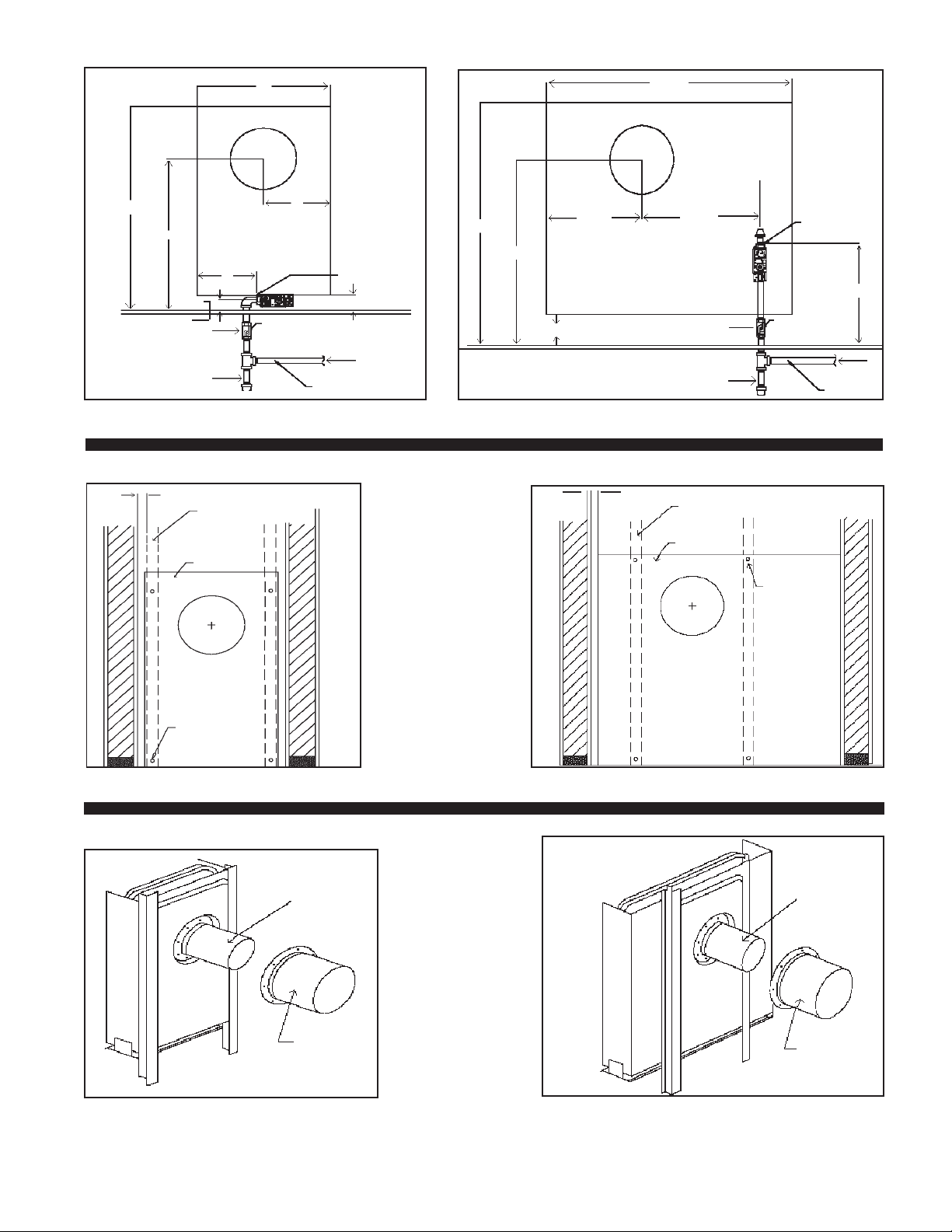
18”
CABINET
34-1/2”
CABINET
29-3/4”
22”
1/2”
Center Line Pipe Elbow
SHUT OFF
V ALVE
DRIP LEG
FIG. 4 / CDV15-C
1” MINIMUM SIDE WALL TYP.
WALL STUDS
16” O.C.
TEMPLATE
9” DIA.
OPENING
8”
1/8” N.P.T.
PRESSURE TAP
9”
GAS VALVE
INLET
1/2”
1/2” BLACK IRON PIPE
FLOOR
GAS
SUPPLY
9” DIA.
OPENING
4”
13-3/8”
FLOOR
31-3/4”
24-1/8”
FIG. 4 / CDV25/33-C
1” MINIMUM SIDE WALL TYP.
16-5/8”
SHUT OFF
VALVE
DRIP
LEG
WALL STUDS 16” O.C.
TEMPLATE
MOUNTING
HOLES
GAS V AL VE
INLET
1/8” N.P.T.
PRESSURE TAP
GAS SUPPLY
13”
1/2” BLACK
IRON PIPE
MOUNTING
HOLES
FIG. 5 / CDV15-C
FIG. 6 / CDV15-C
EXHAUST
TUBE
AIR
INTAKE TUBE
FIG. 5 / CDV25/33-C
EXHAUST
TUBE
AIR
INTAKE TUBE
FIG. 6 / CDV25/33-C
Page 7
Page 8
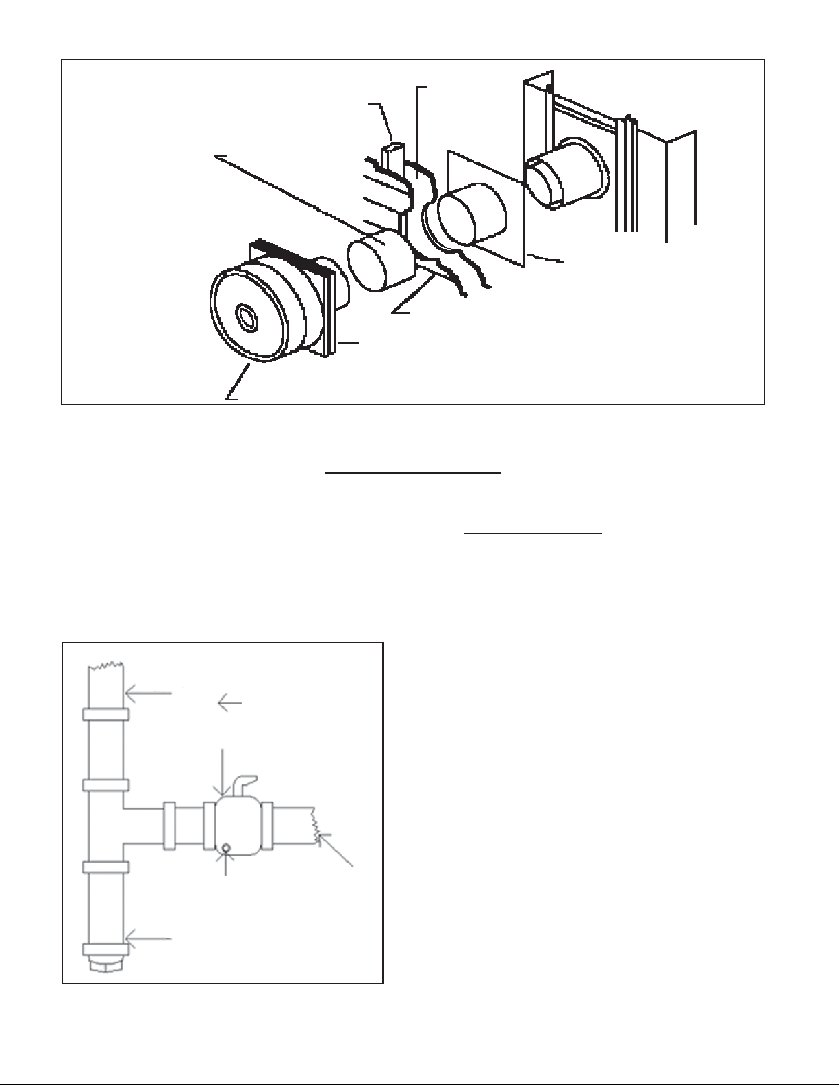
Inside W all
W all Stud
W all Thimble
Extension
W all Thimble
Assembly
Outside W all
Vent Terminal Spacer Plate
V ent T erminal
FIGURE 7
GAS CONNECTION
Make gas connection between manual shut off valve and furnace valve with approved connectors. Compounds
used on threaded joints of gas piping shall be approved for use with L.P gas. The gas lines must be checked for
leaks by the installer with soapy water or liquid detergent, never an open flame. If connections are not
exposed, a pressure test must be run. Be sure to disconnect the gas supply line from the appliance valve before
pressure testing. The manifold pressure is pre-set at the factory and should be 3.5” w.c. for Natural Gas and
10” w .c. for L.P. Gas. The minimum inlet pressure for Natural Gas is 4.5” w .c. and 1 1” w .c. for L.P. Gas, “for
purpose of input adjustment”. The maximum inlet pressure should never exceed 7.0” w .c. on Natural Gas or
14” w.c. on L.P. Gas.
T o heater gas control valve
Manual cut-off valve
Gas
1/8” NPT
Pressure T ap
Drip Leg
FIG. 4-A FOR CDV15, CDV25, and CDV33-C
Supply
Line
Page 8
Page 9
LIGHTING INSTRUCTIONS / MILLIVOLT (SELF GENERATING)
MODELS: CDV155C, CDV156C, CDV255C, CDV256C, CDV335C, CDV336C
FOR YOUR SAFETY READ BEFORE LIGHTING
WARNING: If you do not follow these instructions exactly, a fire or explosion may result causing
property damage, personal injury or loss of life.
A. This appliance has a pilot which must be lighted by hand.
When lighting the pilot, follow these instructions exactly.
B. BEFORE LIGHTING smell all around the appliance area
for gas. Be sure to smell next to the floor because some
gas is heavier than air and will settle on the floor.
WHAT TO DO IF YOU SMELL GAS:
Do not try to light any appliance.
Do not touch any electric switch; do not use any phone in
your building.
Immediately call your gas supplier from a neighbor’s
phone. Follow the gas supplier’s instructions.
LIGHTING INSTRUCTIONS
1 . STOP! Read the information on the safety label.
2. Set thermostat to lowest setting.
3 . “Turn off all electric power to the appliance”.
4 . Remove cabinet.
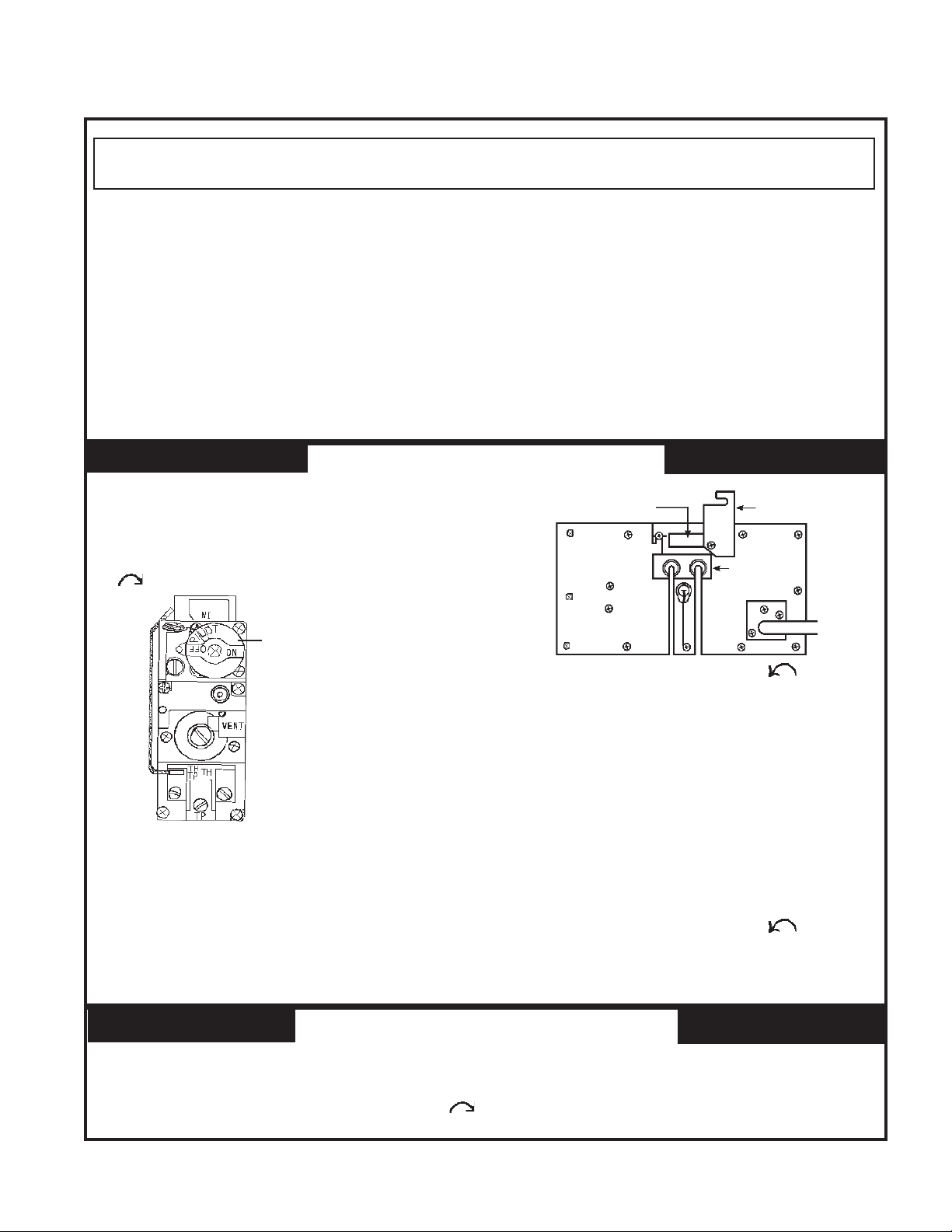
5. Push in gas control knob slightly and turn clockwise
to “OFF”.
Gas Control Knob
If you cannot reach your gas supplier, call the fire
department.
C. Use only your hand to push in or turn the gas control knob.
Never use tools. If the knob will not push in or turn by
hand, don’t try to repair it, call a qualified service
technician. Force or attempted repair may result in a fire
or explosion.
D. Do not use this appliance if any part has been under water.
Immediately call a qualified service technician to inspect
the appliance and to replace any part of the control system
and any gas control which has been under water.
Sight Glass
Sight Glass
Cover
Pilot
9 . Turn gas control knob counterclockwise to “PILOT”.
NOTE: Knob can
not be turned from
“PILOT” to “OFF”
unless knob is
pushed in slightly.
Do not force.
6. Wait five (5) minutes to clear out any gas. Then smell
for gas, including near the floor. If you smell gas,
STOP! Follow “B” in the safety information on the
safety label. If you don’t smell gas, go to the next step.
7. Open sight glass cover.
8. Locate red piezo ignitor button inside gas control
compartment. Locate pilot behind sight glass. (Follow
metal pilot tube from gas control).
10. Push in gas control knob and hold in. Immediately begin a
series of pushing and releasing the red piezo ignitor button,
while observing the pilot through the sight glass. Continue
to spark until pilot is lit. Continue to hold the gas control
knob in for about one (1) minute after the pilot is lit. Release
the gas control knob and it will pop back up. Pilot should
remain lit. If pilot goes out, repeat steps 4 thru 9.
If knob does not pop up when released, STOP and
immediately call your service technician or gas supplier.
If the pilot will not stay lit after several tries, turn the gas
control knob to “OFF” and call your service technician or
gas supplier.
11. Close sight glass cover.
12. Turn gas control knob counterclockwise to “ON”.
13 . Replace cabinet.
14. “Turn on all electric power to the appliance”.
15. Set thermostat to desired setting.
TO TURN OFF GAS TO APPLIANCE
1. Set the thermostat to it’s lowest setting.
2 . “Turn off all electric power to the appliance if service is to be performed”.
3. Open cabinet door.
4 . Push in gas control knob slightly and turn clockwise to “OFF”. Do not force.
5 . Close cabinet door.
P/N 91251 03/07
Page 9
Page 10
PILOT ADJUSTMENT
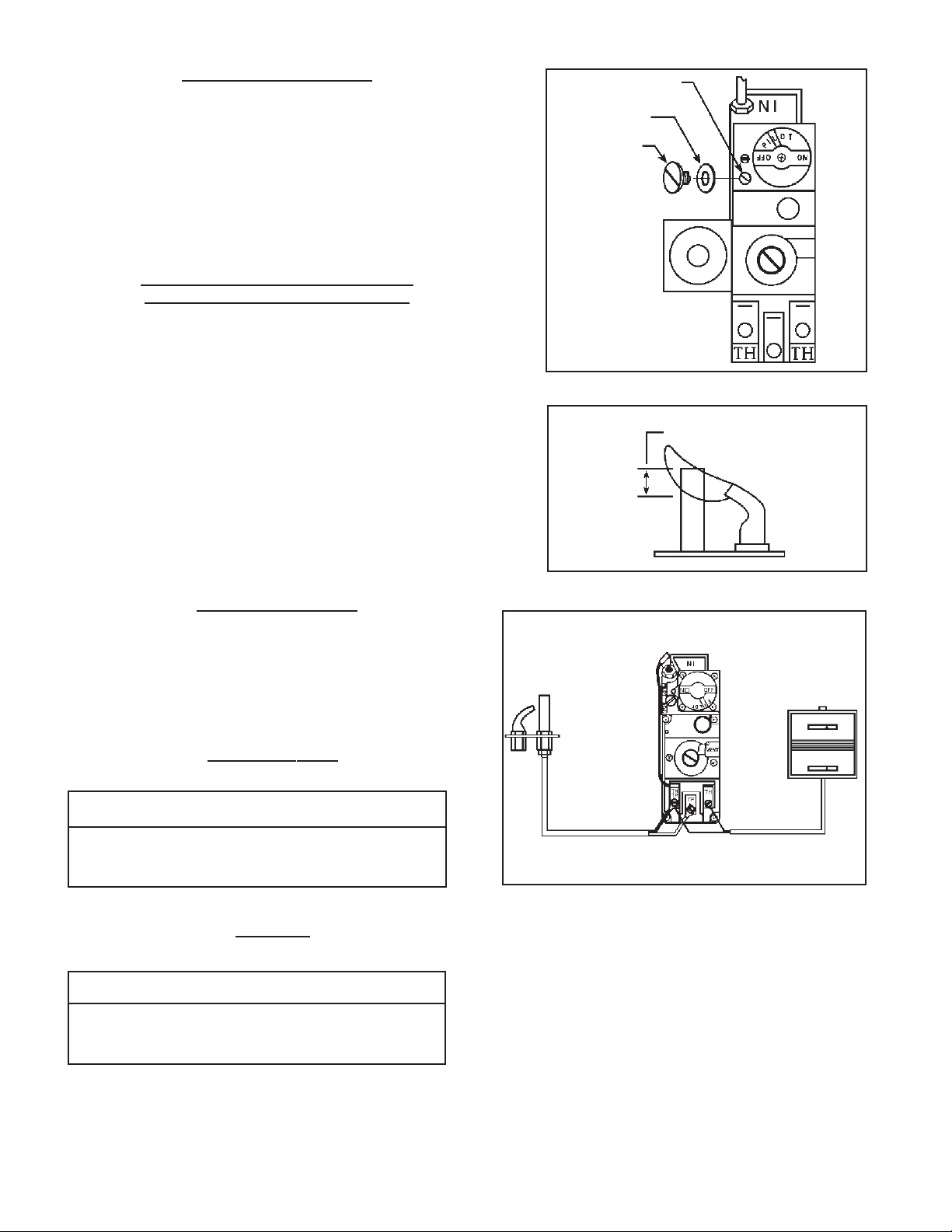
Locate pilot adjustment cap on valve and remove. See Figure 8.
Pilot flame should surround the top 3/8 to ½ inch of powerpile or
thermocouple, see Figure 9. To increase pilot flame, turn pilot
adjustment screw, see Figure 8, counterclockwise. To decrease pilot
flame, turn screw clockwise. After a proper pilot flame is established
replace pilot adjustment cap, be sure gasket located on bottom of
cap head is in place. The gas supply to the pilot is unregulated.
When line pressure exceeds 7” w.c. Natural Gas, 11” w.c. L.P. Gas,
pilot adjustment must be made.
TO REMOVE MAIN BURNER FOR
INSPECTION AND CLEANING
1. Remove outer casing.
2. Disconnect gas supply to valve.
3. Remove 11 screws holding burner door to heat exchanger and
lift out complete burner, valve assembly.
4. After inspecting burner, place back into heat exchanger. Be
sure door gasket is not damaged and will effect a proper seal or
pilot outage will occur.
5. Tighten screws holding burner door to heat exchanger.
6. Connect gas supply back to valve.
7. Install front panel and follow lighting instructions.
NOTE: The furnace and all components must be inspected at least
annually by a qualified service technician. This should include
the burner, heat exchanger, and vent system. Be sure that the
flow of combustion and ventilation air are not obstructed.
BURNER ORIFICE
This appliance equipped only for altitudes 0 - 2,000 ft. If installed
above 2,000 ft., the BTU input must be reduced 4% per 1,000 ft. See
the following orifice chart for the proper orifice for a specific elevation.
Orifice change must be completed by a qualified installer or service
technician.
Pilot Adj. Screw
Gasket
Pilot Adj. Cap
FIGURE 8
Pilot flame should envelop
3/8” - 1/2” of powerpile
or thermocouple
FIGURE 9
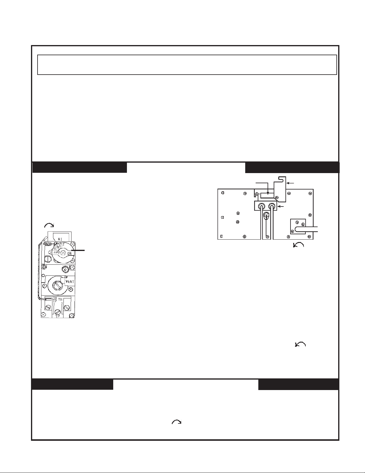
WIRING DIAGRAM
NATURAL GAS
SPECIFIC ELEV A TIONS
MODEL 0 TO 2,000’ 4,000’ 6,000’ 8,000’
NUMBER 2,000’ 4,000’ 6,000’ 8,000’ 10,00’
CDV155C 4 8 49 5 0 51 5 2
CDV255C 2.45mm 41 4 2 4 3 44
CDV335C 2.75mm 37 3 8 4 0 42
ORDER KIT #49800 44-1 HIGH ALTITUDE KIT
L.P. GAS
SPECIFIC ELEVATIONS
MODEL 0 TO 2,000’ 4,000’ 6,000’ 8,000’
NUMBER 2,000’ 4,000’ 6,000’ 8,000’ 10,00’
CDV156C 1.2mm 56 5 7 5 9 6 0
CDV256C 1.55mm 54 5 4 5 5 55
CDV336C 1.65mm 51 5 2 5 2 53
ORDER KIT #49800 44-1 HIGH ALTITUDE KIT
Page 10
Pilot Generator
Leads
Thermostat
Wire
WIRING DIAGRAM
CAUTION: Label all wires prior to disconnection when servicing controls. Wiring errors can
cause improper and dangerous operation. Verify
proper operation after servicing.
Page 11
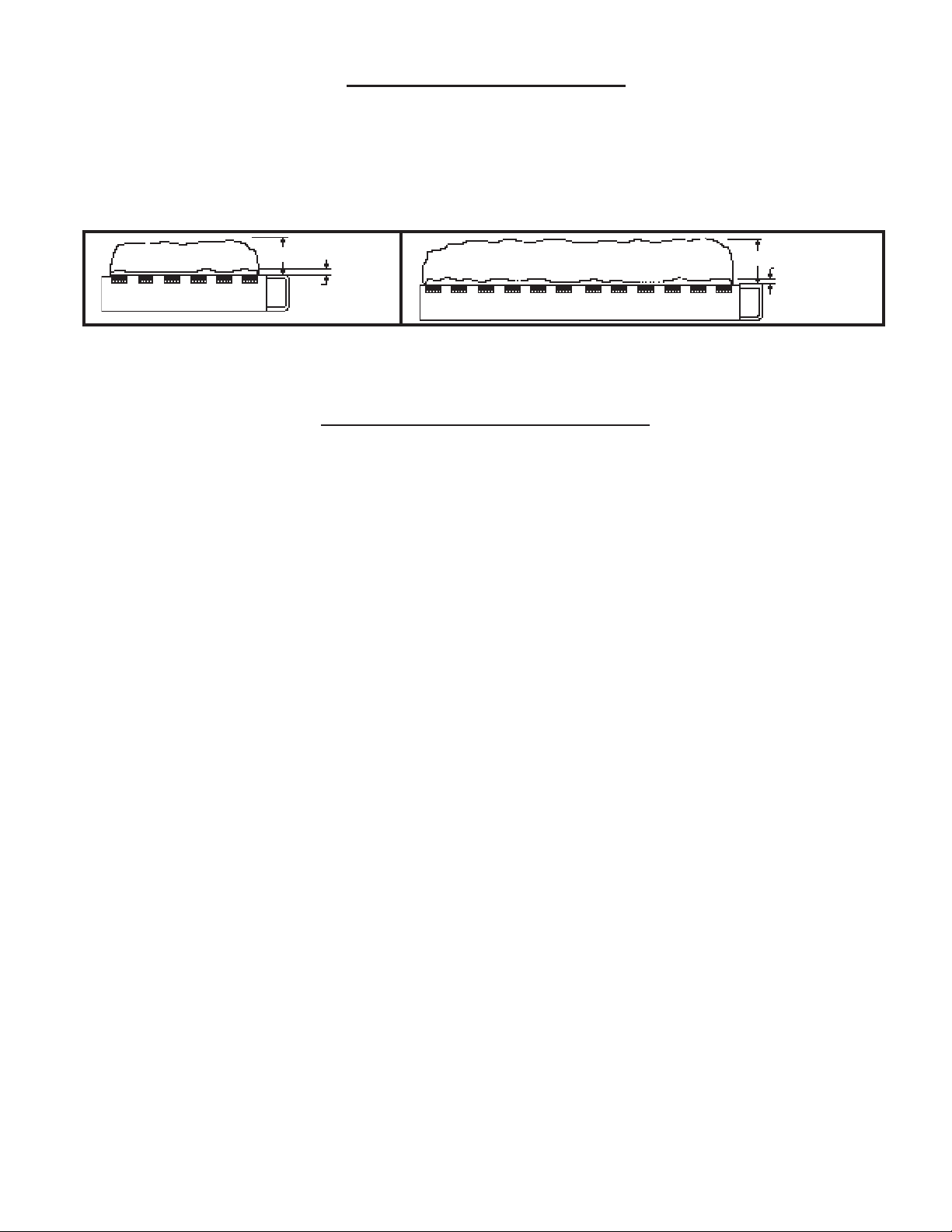
PROPER BURNER FLAME
The burner flame may be observed by raising the sight glass cover. A proper flame will have a dark blue inner mantle
that sits right on top of the burner with a lighter blue outer mantle rising over the burner, see Figure 10. There may be
some yellow where the pilot flame and burner flame meet. There is no primary air adjustment on the burner, and
proper flame is assured since the correct manifold pressure and orificing has been done at the factory .
3” - 4” OUTER FLAME
FIGURE 10 - CDV15-C
3/8” INNER
MANTLE
FIGURE 10 - CDV25/33-C
4” - 5” OUTER FLAME
3/8” INNER
MANTLE
THERMOSTAT INSTALLATION
FOR CDV155C, CDV156C, CDV255C, CDV256C,
CDV335C, CDV336C MODELS ONL Y
Follow the instructions included with the thermostat. If the thermostat is to be wall mounted, select a location in the
same room as the heater, approximately five feet above the floor on an inside wall where it won’t be af fected by heat
or cold sources such as direct sunlight, televisions, fireplaces, hidden hot or cold water pipes, drafts, etc. The
thermostat must not be placed in an adjacent room. The furnace is equipped with a self-generating control system;
never connect to a 24-volt transformer or household electric system. Do not splice or attempt to use more thermostat
wire than is supplied. Connect thermostat wires to thermostat and mount thermostat to wall, run wire to furnace,
securing with insulated staples provided, and connect to valve terminals marked TH, see Figure 8.
Page 11
Page 12
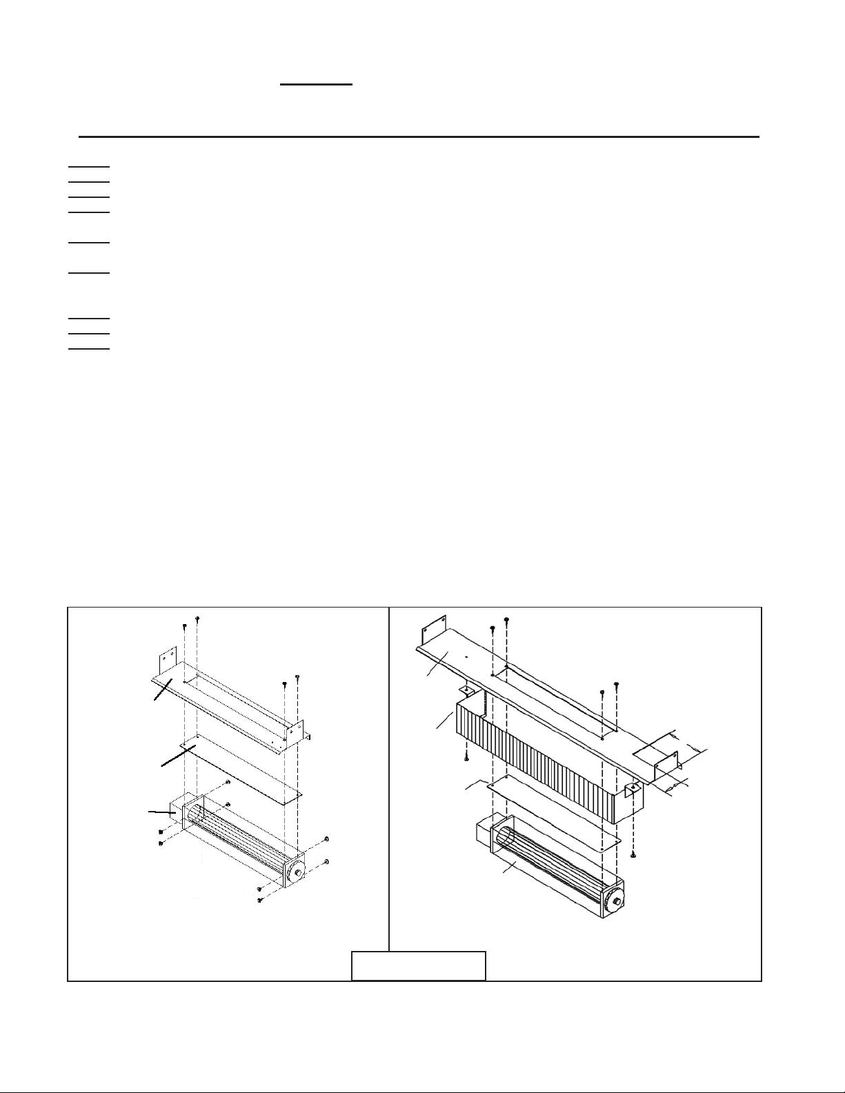
MODEL DVB-3 OPTIONAL BLOWER KIT
INST ALLA TION INSTRUCTIONS
INSTALL ONLY ON CDV15-C / CDV25-C / CDV33 –C SERIES
STEP 1. REMOVE OUTER CASING .
STEP 2. REMOVE FLOOR SHIELD FROM BOTTOM OF HEA TER AND DISCONNECT PIEZO WIRE.
STEP 3. REMOVE AND DISCARD COVER SHIELD. SAVE SCREWS.
STEP 4. A TT ACH BLOWER TO BOTT OM OF FLOOR SHIELD USING SCREWS SA VED IN STEP 3. NOTE: BLOWER
MOTOR SHOULD BE ON OPPOSITE END FROM PIEZO.
STEP 5. FOR MODELS CDV25/33-C, SECURE P/N 43625 BLOWER SHIELD TO BOTT OM OF HEA T SHIELD USING TWO (2)
#8X1/2” SCREWS PROVIDED. SEE FIGURE 11.
STEP 6. CONNECT PIEZO WIRE AND A TT ACH FLOOR SHIELD TO HEA TER. SLIDE THE WHITE CABLE CLAMP
(PROVIDED) OVER BOTH MOTOR LEAD WIRES AND THE POWER CORD. SECURE T O LEFT SIDE OF HEA TER
WITH THE FRONT SCREW USED TO SECURE THE FLOOR SHIELD.
STEP 7. A TT ACH THE JUNCTION BOX TO LEFT SIDE OF WRAPPER USING FOUR #8X1/2” SCREWS PROVIDED.
STEP 8. PLUG POWER CORD INTO A 1 15 VOL T GROUNDED OUTLET.
STEP 9. REPLACE OUTER CASING AND FOLLOW LIGHTING INSTRUCTIONS TO PLACE HEA TER IN OPERA TION.
THE UNIT MUST BE ELECTRICALL Y GROUNDED ACCORDING TO THE NA TIONAL ELECTRICAL CODE ANSI/NFP A NO.
70-1987. THIS APPLIANCE IS EQUIPPED WITH A THREE- PRONG GROUNDING PLUG . FOR YOUR PROTECTION
AGAINST SHOCK HAZARD, THIS APPLIANCE SHOULD BE PLUGGED DIRECTL Y INTO A PROPERL Y GROUNDED THREEPRONG RECEPT ACLE. DO NOT CUT OR REMOVE THE GROUNDING PRONG FROM THIS PLUG .
NOTE: THIS BLOWER ASSEMBLY IS EQUIPPED WITH A TEMPERA TURE ACTIV A TED F AN SWITCH THAT WILL
AUTOMA TICALL Y CYCLE THE BLOWER ON WHEN THE HEA T EXCHANGER HAS REACHED A PREDETERMINED
TEMPERA TURE. ONCE THE BURNER SHUTS OFF, THIS SWITCH WILL CYCLE THE BLOWER OFF AFTER THE HEA T
EXCHANGER COOLS TO THE F AN SWITCH DIFFERENTIAL SETTING. THIS BLOWER WILL NOT OPERATE UNLESS
THE MAIN BURNER IS IN USE.
FLOOR
SHIELD
COVER SHIELD
(Remove &
Discard)
BLOWER
CDV15-C
FLOOR
SHIELD
BLOWER
SHIELD
P/N 43625
COVER SHIELD
(Remove &
Discard)
FIGURE 11
Page 12
3-5/8”
1-3/4”
BLOWER
CDV25-C / CDV33-C
APRIL 2013
P/N 70925
Page 13
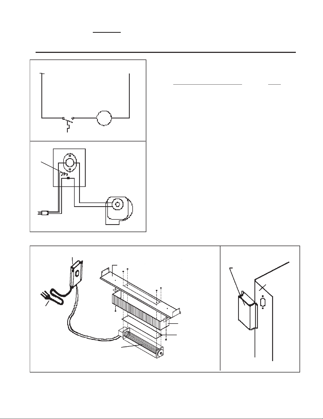
MODEL DVB-3 OPTIONAL BLOWER KIT (Cont’d.)
INST ALLA TION INSTRUCTIONS
INSTALL ONLY ON CDV15-C / CDV25-C / CDV33 –C SERIES
L1
BLACK
BLUE
GREEN
POWER
CORD
LADDER
SCHEMATIC
BLACK
F AN SWITCH
Fan Switch
BLACK
BLACK
Motor
PICTORIAL
SCHEMATIC
BLUE
BLACK
L2
BLOWER
MOTOR
BLACK
PART
PART DESCRIPTION NO.
Blower Housing w/Motor 70201
& Blower
Junction Box 43610
Junction Box Cover 43620
Fan Switch 120 Degree 70 1 10
Cord Set 80202
Cover Shield 43078
Blower Shield CDV25/33-C 43625
If any of the original wire supplied
with this appliance has to be replaced,
it must be replaced with type 105
degree C wire or its equivalent.
FIGURE 12
POWER
CORD
FIGURE 13
JUNCTION BOX
BLOWER
FLOOR
SHIELD
JUNCTION
BOX
WRAPPER
BLOWER
SHIELD
COVER SHIELD (REMOVE AND
DISCARD)
Page 13
Page 14
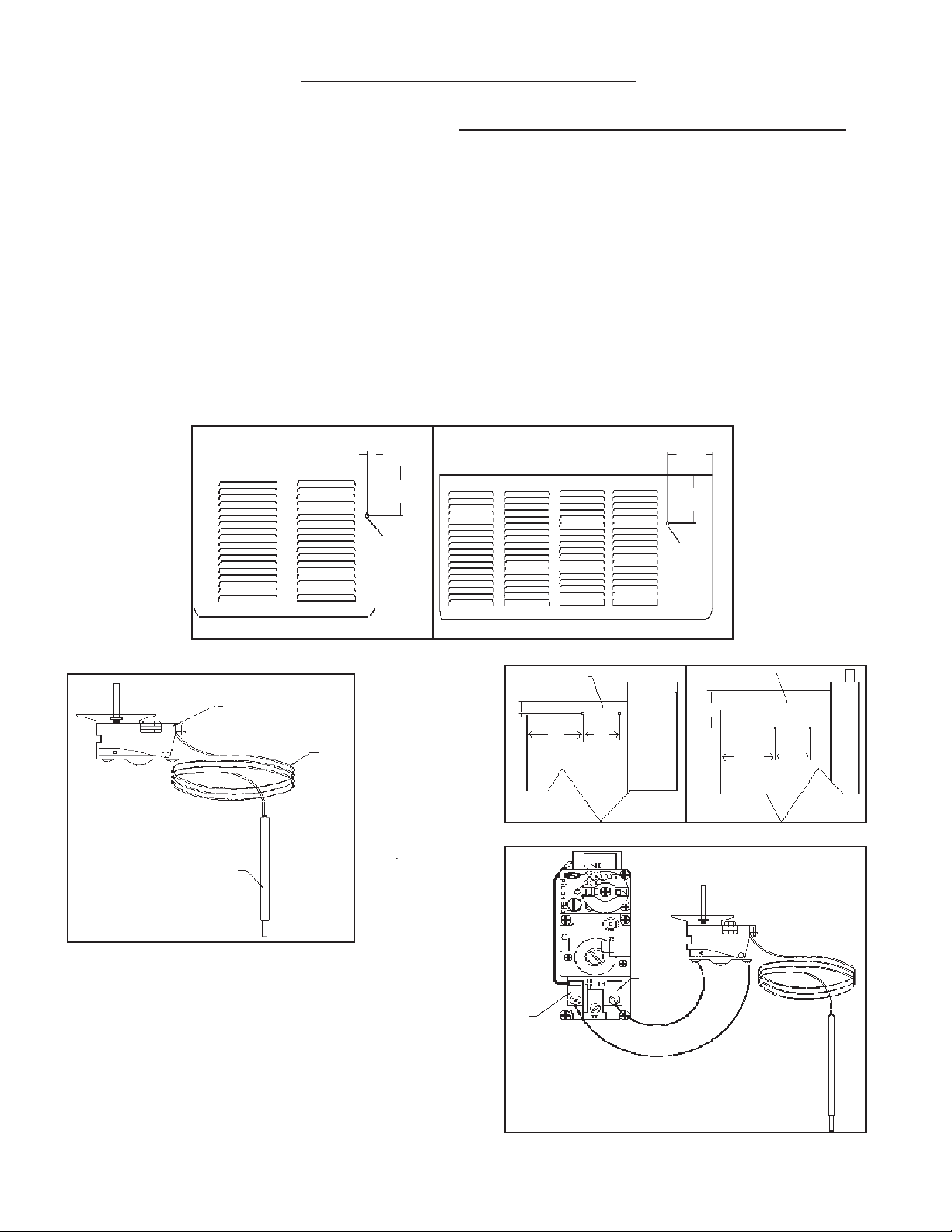
OPTIONAL BBSK INSTALLATION INSTRUCTIONS
STEP 1) LOCATE DIMPLE AT RIGHT REAR OF THE CABINET TOP. SEE FIGURE A.
STEP 2) USING DIMPLE AS A LOCATOR, DRILL A ½” HOLE.
STEP 3) STRAIGHTEN THE CAPILLARY TUBE. DO NOT KINK THE CAPILLARY TUBE OR SENSING
BULB. SEE FIGURE B.
STEP 4) FROM TOP OF HEATER, INSTALL SENSING BULB DOWN AND UNDER THE GAS CONTROL
VALVE SO THAT THE CAPILLARY TUBE IS BETWEEN THE BACK OF THE HEATER AND THE
WALL. SLIDE WHITE CABLE CLAMP (PROVIDED) ONTO SENSING BULB AND SECURE TO THE
BOTTOM OF THE GAS VALVE USING THE 10-24X3/8” SCREW PROVIDED.
STEP 5) SECURE THE CONTROL SWITCH (SEE FIGURE B) TO THE RIGHT SIDE OF THE INNER WRAPPER
USING PREPUNCHED HOLES AND TWO #8 SCREWS PROVIDED. SEE FIGURE C. NOTE:
SWITCH MUST BE INSTALLED TO BE OUTSIDE THE WRAPPER.
STEP 6) RUN THE TWO CONTROL WIRES FROM THE SWITCH DOWN THE RIGHT OUTSIDE OF WRAP-
PER. CONNECT ONE WIRE TO THE “TH” TERMINAL AND ONE TO THE “THPP” TERMINAL ON
THE GAS VALVE. SEE FIGURE D. SLIDE A WHITE CABLE CLAMP (PROVIDED) OVER BOTH
WIRES AND SECURE TO WRAPPER USING SCREW THAT SECURES THE FLOOR SHIELD.
STEP 7) IF HEATER IS NOT INSTALLED TO WALL, FOLLOW INSTRUCTIONS TO DO SO.
STEP 8) REMOVE AND DISCARD THE LIGHTING INSTRUCTIONS SUPPLIED WITH HEATER. REPLACE
WITH LIGHTING INSTRUCTION SUPPLIED IN BBSK KIT.
STEP 9) PLACE CABINET ONTO HEATER, THE CONTROL ROD SHOULD EXTEND UP THROUGH THE ½”
HOLE IN TOP OF CABINET.
STEP 10) PLACE THE CONTROL KNOB ONTO THE CONTROL ROD AND SECURE BY PUSHING DOWN.
STEP 11) FOLLOW THE LIGHTING INSTRUCTIONS TO PLACE THE HEATER IN OPERATION.
CDV15
FIGURE A
Control
Unit
Sensing
Bulb
13/16”
Capillary
Tube
3-1/4”
DIMPLE
CDV25/33
RIGHT SIDE OF
INNER WRAPPER
5/8”
3”
CDV15
FIGURE C
6-1/2”
3-1/4”
DIMPLE
RIGHT SIDE OF
INNER WRAPPER
1-7/8”
2”
3-1/8”
2”
CDV25/33
FIGURE B
Page 14
Vent
“TH”
“TH-TP”
FIGURE D
Page 15
LIGHTING INSTRUCTIONS for Optional BBSK
FOR YOUR SAFETY READ BEFORE LIGHTING
WARNING: If you do not follow these instructions exactly, a fire or explosion may result causing
property damage, personal injury or loss of life.
A. This appliance has a pilot which must be lighted by hand.
When lighting the pilot, follow these instructions exactly.
B. BEFORE LIGHTING smell all around the appliance area
for gas. Be sure to smell next to the floor because some
gas is heavier than air and will settle on the floor.
WHAT TO DO IF YOU SMELL GAS:
Do not try to light any appliance.
Do not touch any electric switch; do not use any phone in
your building.
Immediately call your gas supplier from a neighbor’s
phone. Follow the gas supplier’s instructions.
LIGHTING INSTRUCTIONS
1. STOP! Read the information on the safety label.
2. Set temperature control knob located on top of cabinet to
lowest setting.
3 . Turn off all electric power to the appliance.
4 . Remove temperature control knob by pulling straight up.
5 . Remove cabinet.
6. Push in gas control knob slightly and turn clockwise
to “OFF”.
If you cannot reach your gas supplier, call the fire
department.
C. Use only your hand to push in or turn the gas control knob.
Never use tools. If the knob will not push in or turn by
hand, don’t try to repair it, call a qualified service
technician. Force or attempted repair may result in a fire
or explosion.
D. Do not use this appliance if any part has been under water.
Immediately call a qualified service technician to inspect
the appliance and to replace any part of the control system
and any gas control which has been under water.
Sight Glass
Sight Glass
Cover
Pilot
10. Turn gas control knob counterclockwise to “PILOT”.
Gas Control Knob
NOTE: Knob can
not be turned from
“PILOT” to “OFF”
unless knob is
pushed in slightly.
Do not force.
7. Wait five (5) minutes to clear out any gas. Then smell
for gas, including near the floor. If you smell gas,
STOP! Follow “B” in the safety information on the
safety label. If you don’t smell gas, go to the next step.
8. Open sight glass cover.
9. Locate red piezo ignitor button inside gas control
compartment. Locate pilot behind sight glass. (Follow
metal pilot tube from gas control).
11. Push in gas control knob and hold in. Immediately begin a
series of pushing and releasing the red piezo ignitor button,
while observing the pilot through the sight glass. Continue
to spark until pilot is lit. Continue to hold the gas control
knob in for about one (1) minute after the pilot is lit. Release
the gas control knob and it will pop back up. Pilot should
remain lit. If pilot goes out, repeat steps 4 thru 9.
If knob does not pop up when released, STOP and
immediately call your service technician or gas supplier.
If the pilot will not stay lit after several tries, turn the gas
control knob to “OFF” and call your service technician or
gas supplier.
12. Close sight glass cover.
13. Turn gas control knob counterclockwise to “ON”.
14 . Replace cabinet.
15 . Replace temperature control knob.
16. Turn on all electric power to the appliance.
17. Set temperature control knob to desired setting.
TO TURN OFF GAS TO APPLIANCE
1. Set the temperature control knob to it’s lowest setting.
2 . Remove temperature control knob.
3 . Turn off all electric power to the appliance if service is to be performed.
4 . Remove cabinet.
5 . Push in gas control knob slightly and turn clockwise to “OFF”. Do not force.
6 . Replace cabinet.
7 . Replace temperature control knob.
Page 15
P/N 91285 03/07
Page 16

MODEL NUMBERS
MILLIVOLT
NAT. GAS L.P. GAS
CDV155C CDV156C
COZY DIRECT VENT WALL FURNACE - CDV15-C
DIRECT VENT WALL FURNACE
PARTS LIST
Prices and specifications subject to change
without notice. All prices are F.O.B. factory.
3
1
9
5
4
10
17
20
16
14
OPTIONAL VENT EXTENSIONS
= VK1525/9-15 Vent Kit Assembly
= VK1525/15-24 Vent Kit Assembly
21
23
11
12
27
25
26
41
37
44
43
34
32
38
33
35/36
3
56
18
29
40
39
30
31
52
28
16
15
49
OPTIONAL BLOWER
ASSEMBLY / DVB-3
48
51
DVB3 Blower Kit
also includes:
43078 Cover Plate
43625 Blower Shield
for CDV25/33
50
47
22
46
53
45
Page 16
REV. 04/2013
Page 17
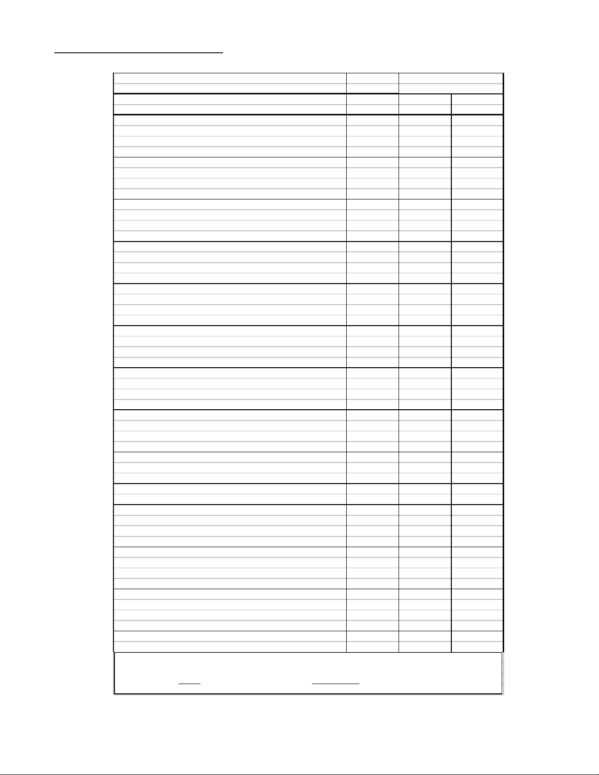
HOW TO PROPERLY ORDER PARTS: In addition to part description and part number, please give model number, serial
R
d
r
d
r
r
x
number, and type of gas used. This information can be found on the rating plate located in control compartment.
NAT. CDV155C
MODEL NUMBERS L.P. CDV156C
REF. PART LIST
PART DESCRIPTION NO. NUMBE
Heat Exchanger 1 42565
Vent Exhaust Tube Gasket - 5-3/8" Circle 3 70062
Wrapper Assembly w/Comb. Air Pan 4 43051
Cabinet 5 42555
Front Heat Shi el
Bottom Heat Shield 10 43075
Vent Cap & Spacer Plate 11 & 12 43145
Air Intake Tube Assy. (5-9" Wall) 6-3/4" Dia. 14 43200
Air Intake Tube Assembly (9-15" Wall) 15 43810
Air Intake Tube Assembly (15-24" Wall) 49 43705
Air Intake Tube Gasket - 8-1/2" Circle 16 70061
Vent Exhaust Tube Assy. (5-9" Wall) 4-3/16" Dia. 17 43206
Vent Exhaust Tube Assembly (9-15" Wall) 18 43820
Vent Exhaust Tube Assembly (15-24" Wall) 52 43717
Wall Thimble Assembly (5 - 9" Wall) 20 43230
Wall Thimble Extension (5-9" Wall) 21 43236
Wall Thimble Extension (9-15" Wall) 22 43835
Wall Thimble Extension (15-24" Wall) 53 43730
Wall Thimble Gaske t - 11x11" 23 70066
Burner Access Door 25 43247
Heat Exchanger Door Gasket - 11-3/8x5-1/2"(Burner Gasket) 26 70060
Main Bur ne
Manifol
Manifold Gasket - 2x2" 29 70065
Main Burner Orifice, Natural Gas 30 70040
Main Burner Orifice, L.P. Gas 31 70041
Sight Glass Assy. (Glass, Cover & Gasket included) 32 43252
Sight Glass Cove
Sight Glass/Pilot Burner, Gasket - 3-1/2x2-3/4" 34 70064
Pilot Burner Q350A2493, Natural Gas 35 70007
Pilot Burner Q350A2501, L.P. Gas 36 70008
Electrode 37 70052
Electrode Wire 38 70051
Piezo Sparke
Piezo Sparker Bracket 40 43263
Valve, MV,
Valve, MV,
Generator, Q313A1014 for CDV155 / CDV156 43 70098
Pilot Tubing w/fittings 44 70012
Thermostat 45 74592
Thermostat Wire N/A 74518
Insulated Staples N/A 74209
Air Pan Assembly w/Gasket for CDV15 N/A 43059
90 Degree Elbow 56 70352
Vent Terminal Shield N/A 34950
Blower Housing w/Motor & Blower 46 70201
Junction Bo
Junction Box Cover 48 43620
Fan Switch 120 Degrees 50 70110
Cord Set 51 80202
Cover plate N/A 43078
ATTN: CONTRACTORS an d SERVICE TECHNIC IANS
listed above are f o r your conv en ience. For p r o m p t p arts service, contact th e wholesaler from which you purchased
your Cozy heater. NOTE
6003, Natural Gas for CDV155 41 84085
Dexen
6003LP, L.P. Gas for CDV156 41 84086
Dexen
, we only sell parts through our wholesalers, but the prices
: parts an d schematic drawings on curren t models are shown at www.cozyheaters.com.
9 43081
27 70005
28 70031
33 43258
39 80016
47 43610
PRICE
-$
Page 17
JUNE 2015
REV . 04/2013
Page 18
MODEL NUMBERS
NATURAL GAS L.P. GAS
CDV255C CDV256C
Prices and specifications subject to change
without notice. All prices are F.O.B. factory.
DIRECT VENT WALL FURNACE
PARTS LIST
CDV335C CDV336C
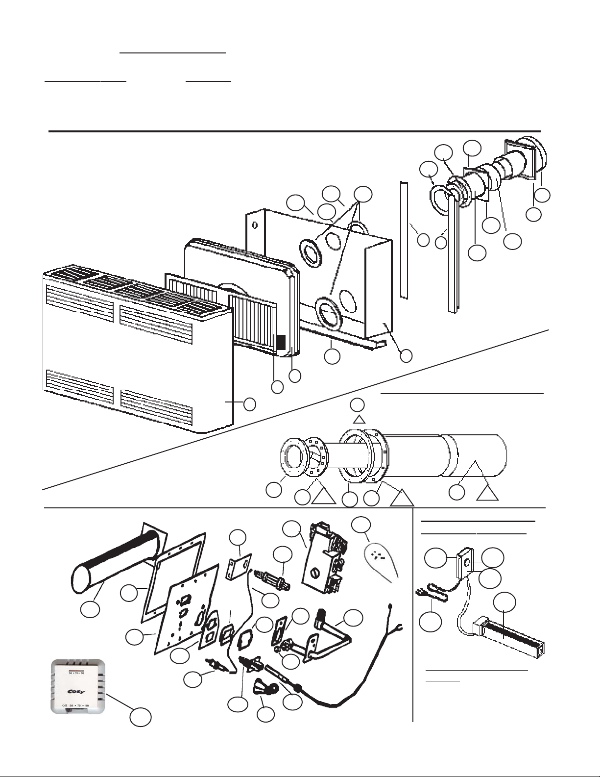
COZY DIRECT VENT WALL FURNACE - CDV25-C / CDV33-C
24
18
(Ref. No. 61, 62, & 63
Not illustrated)
62
63
61
20
17
7
21
6
22
15
11
12
27
26
25
31
38
10
2
1
9
3
20
19
59
OPTIONAL VENT EXTENSIONS
= VK15/25-9-15” Vent Kit Assembly
= VK33/9-15” Vent Kit Assembly
= VK15/25-15-24” Vent Kit Assembly
17
16
58
23
60
OPTIONAL BLOWER
37
39
41
ASSEMBLY / DVB-3
48
50
47
32
36
29
28
51
46
42
33
35
30
34
40
56
Page 18
DVB3 Blower Kit also
includes:
43078 Cover Plate
43625 Blower Shield for
CDV25/33
REV. 04/2013
Page 19
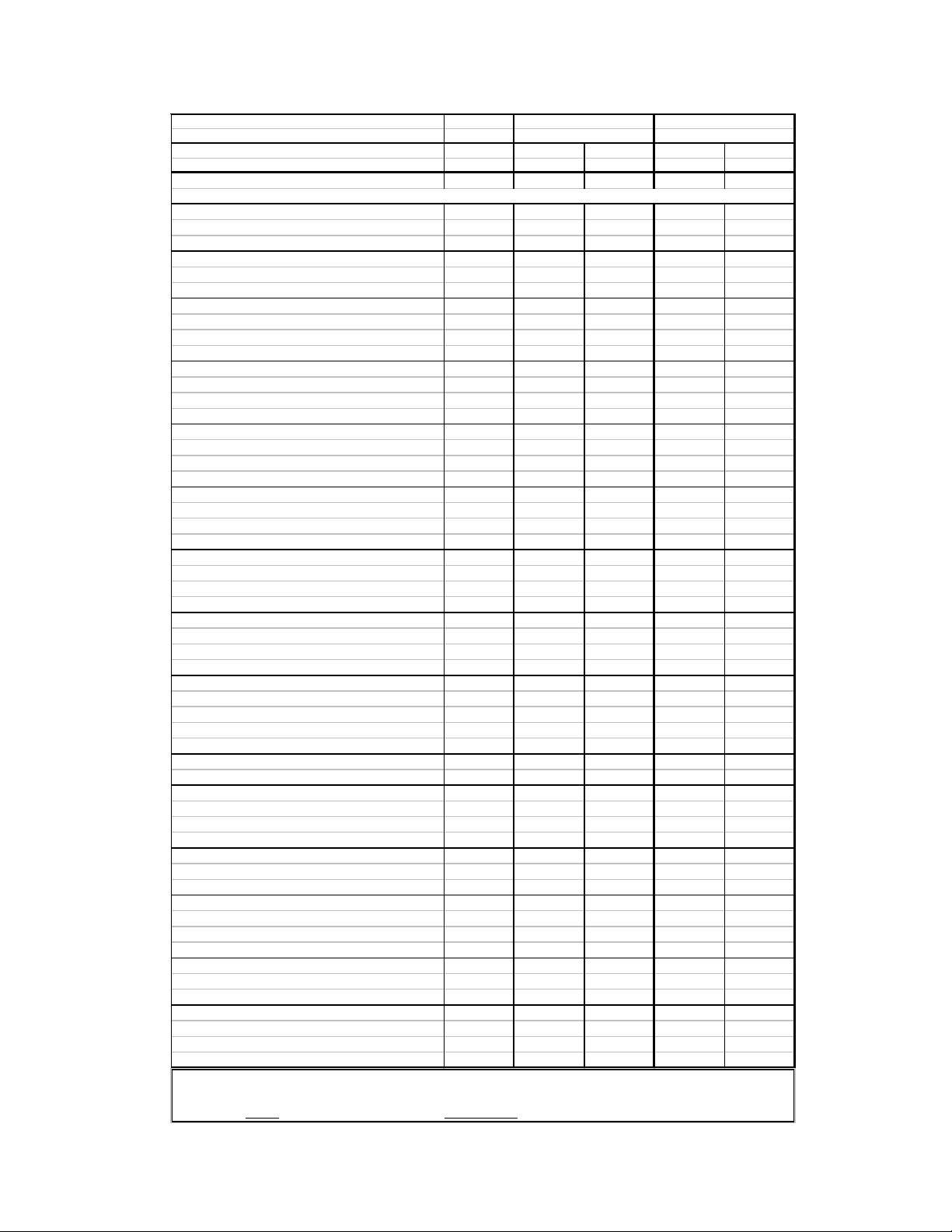
HOW TO PROPERLY ORDER PARTS: In addition to part description and part number, please give model number, serial
MODEL NUMBERS
L.P
CDV256C
CDV336C
A
O
O
C
C
r
number, and type of gas used. This information can be found on the rating plate located in control compartment.
NAT. CDV255C CDV335C
.
RT DESCRIPTIONN
P
Heat Exchanger Kit, INCLUDES 1 42770 42770
Wrapper (Ref. # 2), Right and Left Leg (Ref. # 6 & 7), AND Comb. Air Pan Assembly w/Gas kets (Ref. # 63)
Cabinet 3 42755 42755
Leg, Right 6 43495 43495
Leg, Left 7 43494 43494
Front Heat Shield Assembly 9 43481 43481
Bottom Heat Shield Assembly 10 43473 43473
Vent Cap with Spacer Plate 11 & 12 43145 43145
Air Intake Tube Assy. (5-9" Wall) 6-3/4"Dia. 15 43200 43200
Air Intake Tube Assy. (9-15" Wall) 16 43810 43810
Air Intake Tube Assy. (15-24" Wall) 58 43705 N/A
Air Intake Tube Gas ket - 8-1/2" Circle 17 70061 70061
Vent Exhaust Tube Assy. (5-9" Wall) 4-3/16" dia. 18 43530 43538
Vent Exhaust Tube Assy. (9-15" Wall) 19 43820 43828
Vent Exhaust Tube Assy. (15-24" Wall) 59 43717 N/A
Vent Exhaust Tube Gasket (Requires 4) 5-3/8" Circle 20 70062 70062
Wall Thimble (5-9" Wa ll) 21 43552 43552
Wall Thimble Extension (5-9" Wall) 22 43236 43236
Wall Th imble Extension (9-15" Wall) 23 43835 43835
Wall Thimble Extension (15-24" Wall) 60 43730 N/A
Wall Thimble Gasket - 11x11" 24 70066 70066
Burner Access Door 25 43247 43247
Burner Access Door Gasket - 5-1/2x11-3/8" 26 70060 70060
Burner 27 70006 70006
Manifold 28 70032 70032
Manifold Gasket - 2x2" 29 70065 70065
Main Burner Orifice (Nat. Gas) 30 70048 70047
Main Burner Orifice (L.P. Gas) 30 70039 70049
Si ght Glass Assy. (Glass, Cover & Gasket Included) 31 43252 43252
Si ght Glass Cover 32 43258 43258
Si ght Glass/Pilot Burner, Gasket - 3-1/2x2-3/4" 33 70064 70064
Pilot Burner Q350A2493 (Nat . Gas) 34 70007 70007
Pilot Burner Q350A2501 (L.P. Gas) 34 70008 70008
Electrode 35 70052 70052
Electrode Wire 36 70051 70051
Piezo Sparker 37 80016 80016
Piezo Sparker Bracket 38 43263 43263
Valve, M V,
Valve, M V,
Pilot Generator, Q313A1014 Millivolt 40 70098 70098
Pilot Tubing w/fittings 41 70012 70012
Thermostat, Millivolt 42 74592 74592
Thermostat Wire N/A 74518 74518
Insulated Staples N/A 74209 74209
Gasket, Air Pan Top & Bottom (15-1/4x1) 61 *70074 *70074
Gasket, Air Pan Sides (25x1) 62 *70073 *70073
90 Degree Elbow 56 70352 70352
Vent Terminal Shield N/A 34950 34950
Blower Housing w/Motor & Blowe
Junction Box 47 43610 43610
Junction Box Cover 48 43620 43620
Fan Switch 120 degree 50 70110 70110
Cord Set 51 80202 80202
Cover Plate N/A 43078 43078
Blower Shield N/A 43625 43625
Left Air Intake Baffle N/A 43528 43528
Right Air Intake Baffle N/A 43526 43526
ATTN: CONTRACTORS and S ERVICE TECHNICIANS
listed above are for your convenience. For prompt parts service, contact the wholesaler from which you purchased your
Cozy heater. NOTE
6003, Natural Gas 39 84085 84085
Dexen
6003LP, L.P. Gas 39 84086 84086
Dexen
: Parts & schematic drawings on current models are shown at
REF. PART L IST PART LIST
.N
46 70201 70201
, we only sell parts through our wholesalers, but the prices
.PRI
www.coz yhe aters.com
ENO.PRI
.
E
Page 19* Requires 2
REV . 04/2013 / JUNE 2015
Page 20
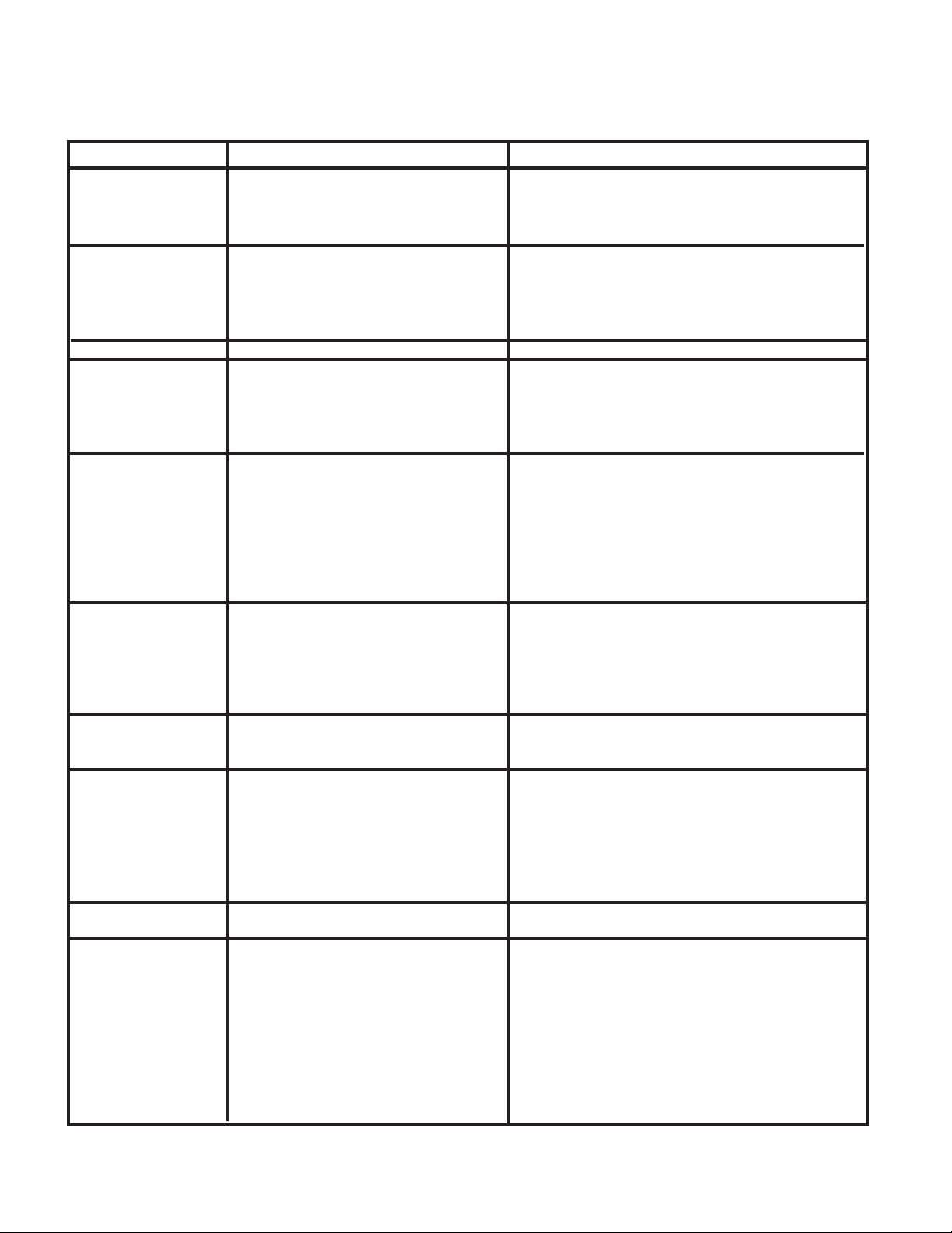
TROUBLE SHOOTING CHAR T
For use by a qualified installer or service technician.
SYMPTOM POSSIBLE CAUSES CORRECTIVE ACTION
Flame too large 1. Defective operator section of valve. 1. Replace valve.
2. Burner orifice too large. 2. Check with local gas company for proper oriifce
- size and replace.
3. If installed above 2,000 ft. 3. See burner orifice section, Page 10.
Yellow burner flame 1. Clogged burner ports. 1. Remove main burner and check for obstructions in
throat, ports, and orifices. Clean - but do not
enlarge ports or orifices.
2. Obstruction around vent cap. 2. Make sure area around vent cap is clear, be sure
vent system is sealed.
Gas odor 1. Gas leak. 1. See Page 1.
Delayed Ignition 1. Pilot flame too small. 1. Adjust pilot flame.
2. Burner ports clogged at pilot. 2. Clean burner ports (do not enlarge).
3. Low gas pressure. 3. Check gas supply pressure.
4. Pilot decreases in size when 4. Supply piping is too small. Consult local gas
main burners come on. company or competent installer.
Failure to Ignite 1. Main gas off. 1. Open all manual gas valves.
2. Thermostat not set high enough 2. Set thermostat to higher temperature.
to call for heat.
3. Clogged burner orifice. 3. Clean burner orifice, (do not enlarge).
4. Thermostat wired wrong or defective. 4. Check wiring, jump across thermostat terminals
at valve, if valve opens - re-check wires, replace
thermostat.
5. Defective valve. 5. Replace valve.
Burner won’t 1. Defective or damaged thermostat 1. Can be checked by removing wire from valve
turn off wire, or thermostat. terminal. If valve goes off, replace wire or
thermostat.
2. Thermostat location. 2. Follow instructions, check location.
3. Defective or sticking valve. 3. Clean or replace valve.
4. Excessive gas pressure. 4. Contact utility supplying gas.
Incorrect gas 1. Gas input not checked. 1. Re-check gas input.
input 2. Clogged orifice. 2. Clean orifice with a smooth wood toothpick,
do not enlarge.
Not enough heat 1. Furnace undersized. 1. This is especially true when a dwelling or room
is enlarged. Have the heat loss calculated and
compare to furnace output. Your gas company can
supply you with this information. If furnace is
undersized, replace with correct size unit.
2. Thermostat set too low. 2. Raise temperature setting.
3. Incorrect supply pressure. 3. Check supply pressure.
Too much heat 1. Thermostat set too high. 1. Lower temperature setting.
2. Combination control valve stuck open. 2. Replace combination control valve.
Pilot and main 1. Weak powerpile or thermocouple. 1. Check millivoltage and replace if low.
burner go out 2. Input too high. 2. Check input rate.
during normal 3. Cover around pilot lighter hole not 3. Tighten wing nuts securing cover and sight glass.
operation air tight. Check and replace gasket if needed.
4. Vent tubes not properly installed 4. Follow instructions. Check both exhaust and
or sealed. air intake tubes, and vent cap. Be sure all
gaskets are in place and properly sealed. Use
only tubes and vent cap supplied. Do not alter
vent tubes or cap.
5. Incorrect vent tubes. 5. Replace with correct tubes.
Page 20
Page 21
MAINTENANCE INSTRUCTIONS
For proper and safe operation keep furnace and
furnace area clean. At regular intervals turn
control valve to off, let cool and clean inside
control compartment and under heater . T o clean
front panel use only a damp cloth, do not use
any kind of solvent or cleaning fluid that could
leave a residue or invisible coating that would
burn or give off fumes when furnace is turned
on.
Have the furnace checked, cleaned, and repaired
by a qualified service technician. Check venting
system, pilot, and burner operation prior to use each
year.
Follow a regular service and maintenance
schedule for safe and efficient operation.
Do not obstruct combustion and ventilation air.
Examine the venting system as a routine part of
the safety performance check on an annual basis.
SERVICE RECORD
If the air intake tube or the exhaust tube is
removed, follow Step 3 of the installation section
for re-assembly. Be sure to check gaskets and
replace if there is any sign of damage.
If the heat exchanger is removed, check the heat
exchanger intake gasket and replace if there is
any sign of damage. Be sure the gasket is in
place when the heat exchanger is replaced.
Failure to replace any gasket that has been
damaged may result in property damage, personal
injury or loss of life.
WARNING
THIS IS A GAS-FIRED APPLIANCE. KEEP
THE AREA CLEAR OF GASOLINE AND
OTHER FLAMMABLE VAPORS AND
LIQUIDS. ALL COMBUSTIBLE MATERIAL
MUST BE KEPT CLEAR OF THIS AREA TO
AVOID FIRE OR EXPLOSION.
Page 21
Page 22
LIMITED WARRANTY
p
p
t
f
r
d
o
N
A
Y
Y
R
W
Y
C
Cozy Heating Systems LLC warra nt s to th e
origi nal user the accompanying product for the period
specified herein, provided said product is installed,
operated, maintained, serviced, and used according to
the instructions and specifi cations acco mpanying th e
roduct. AS OUTLINED IN OUR
INSTRUCTIONS, ANY WARRANTY
CONSIDERATIONS ARE CONTINGENT ON
INST ALL ATION BY A QUALI FIED I NSTALLE R
(CONTRACTOR). SELF-INSTALLATION IS
PROHIBITED AND WILL INVALIDATE YOUR
WARRANTY.
If within a period of one year from the date of
installation of the product, any part supplied by the
manufacturer proves to be defective due to
workmanship or material, it will replace such part,
rovided parts have not been subjected to misuse,
alteration, neglect, or accidents. The term of the
warranty for the heat exch anger and burners is covered
in Tabl e A below. Any clai m not mad e wi th in ten (10)
days af ter the expiration of the warranty period sh all be
deemed waived by th e u s er .
The manufacturer shall have no liability or be
requ ired to perf orm an y ob ligati on under this warra nty
unless, when req uested, the user returns, at the user’s
expe nse , the c ompo nent or pr oduct cl aimed d efec tive ,
to the manufacturer for inspection, to enable the
manufacturer to determine if the claimed defect is
covered by this warranty.
No charges for freight, labor or other
expenses incurred in the repair, removal, or
re place men t of any product or c omp onent claime d to be
defective, will be paid by the manufactu rer to the user,
and the manufacturer will not be liable for any
expenses incurred, by the user, in remedying any defect
in t he product.
Service under this warranty is the
responsibility of the installer. In the event service
Warran ty Period
Product
Cozy Gas Fired Flo or Furna c e 10 Years 1 0 Years
Co zy Gas Fi re d Wa l l Fu rnace 10 Yea rs 1 0 Ye ar s
Cozy Gas Fired Ven ted Con sole Heate r 10 Years 1 0 Years
Cozy Gas Fired Direct Vent Heater 10 Years 10 Years
Cozy Gas Fired Cou nt er flo w Furnace 10 Years 1 0 Years
Cozy Gas Fired Cou nt er flo w Direct Vent Furnac e 10 Year s 1 0 Years
C ozy Gas Fired Mobi le Ho me Direct Vent Furnace 10 Years 10 Years
Cozy Gas Fired Hi- Effi c ient Dire ct Vent Wall Furnace 10 Years 1 0 Years
Cozy Gas Fired Direct Vent Baseboard Heater 10 Years 10 Years
Cozy Fan-Type, Direct Vent Through-The-Wall Gas Heater 10 Years 10 Years
Cozy Blue Flame Vent Free Heater N/A 10 Years
Cozy Infra-Red Vent Free Heater N/A N/A
TABLE A
under this warran ty is needed, the user of the produc
shall request such service directly from the installer. I
the user is unable to locate the installer, the use
should write directly to the manufacturer, and the
name of an alternativ e servic e s ource will be supplied.
Th e p roduc t safet y regis tratio n car d (packe
ins ide the applia nce) mu s t be completed an d returned t
th e fac to r y.
THIS WARRANTY IS EXPRESSLY I
LIEU OF ANY OTHER WARRANTIES, EXPRESS
OR IMPLIED (WHETHER WRITTEN OR ORAL).
ANY IMPLIED WARRANTY OF
MERCHANTABILITY OR OF FITNESS FOR
PARTICULAR PURPOSE IS EXPRESSLY LIMITED
TO THE DUR AT ION OF T HE MANUFAC T URER’S
EXPRE SS, WRIT TEN WARR ANTY.
UNDER NO CIRCUMSTANCES SHALL
THE MANUFACTURER BE LIABLE FOR AN
SPECIAL, INDIRECT OR CONSEQUENTIAL
DAMAGES OR EXPENSES ARISING DIRECTL
OR INDIRECTLY FROM ANY COMPONENT O
FROM THE USE THEREOF. THE REMEDIES SET
FORTH HEREIN SHALL BE THE EXCLUSIVE
REMEDIES AVAILA B LE TO THE USE R AND ARE
IN LI EU OF ALL OTHER REMEDIES.
SOME STATES DO NOT ALLO
LIMITATIONS ON HOW LONG AN IMPLIED
WARRANTY LASTS, SO THE ABOVE
LIMITATIONS MAY NOT APPLY TO YOU.
SOME STATES DO NOT ALLOW THE
EXCLUSION OR LIMITATION OF INCIDENTAL
OR CONSEQUENTIAL DAMAGES, SO THE
ABOVE LIMITATIONS OR EXCLUSIONS MA
NOT APPLY TO YOU.
THIS WARRANTY GIVES YOU SPECIFI
LEGAL RIGHTS, AND YOU MAY ALSO HAVE
OTHER RIGHTS, WHICH VARY, FROM STATE
TO STATE.
Heat Exchanger/Tubes Burners
COZ Y HEAT IN G SY ST E M S L L C
3230 INDUSTRIAL PARKWAY. – JEFFERSONVILLE, IN 47130
 Loading...