

Cozum GP922, GP722 Instruction Manual

Sayfa 1/15
GP922
GP722
GAS TILTING PAN
INSTRUCTION MANUAL

Sayfa 2/15
CONTENTS
INSTALLATION INFORMATION
A. AIMS AND SCOPE
B. RESPONSIBLITIES
C. SIGNS
1. DEVICE SPECIFICATIONS
1.1. TECHNICAL SPECIFICATIONS
2. TRANSPORTATION AND INSTALLATION OF THE PRODUCT
3. SAFETY WARNINGS
4. COMING THINGS TOGETHER WITH THE PRODUCT
5. DEVICE DESCRIPTION/EXPLANATION
6. PLACING THE DEVICE AND PREPARING IT FOR START UP
7. PRE-INSPECTIONS TO BE PERFORMED FOR START UP
8. START UP
9. GAS CONTROL
10. GAS DIAGRAM
11. GAS EQUIPMENTS
12. CLEANING THE DEVICE
14. SAFE LIFE
15. CHANGE THE GAS ENJECTOR
Sayfa 3/15
A. AIMS AND SCOPE
Descriptions for safe use and maintenance of the product
B. RESPONSIBLITIES
Responsibilities of Product’s Owner: The product’s owner is responsible for applying of
safety rules stated in this Instruction Manual or getting them applied by delegating his
authorities and risks, which may arise due to not applying. The product’s owner is also
responsible for the periodical maintenance of the machine.
Responsibilities of the Manufacturers: The manufacturer is responsible for the risks due
to manufacturing and assembling faults, even though all requirements stated in this manual
have been fulfilled.
C. SIGNS
WARNING: This sign indicates that it must be complied with the instructions related
to the subject; otherwise, the risky conditions, in which there can occur some
damages and dangers
CAUTION: This sign indicates any risky conditions, which can cause damages in
material and injuring of people, provided that one does not pay attention and states
that one must be careful.
DANGER: This sign indicates high risky conditions in which people can be injured,
provided that one does not pay attention and the rules always to be complied with.
DANGER: This sign indicates high risky conditions in which the people can be injured
or can die due to electrical shock.
Equipotential connection terminal
(If necessary, it must be connected to other equipment to make equal the potential)
Sayfa 4/15
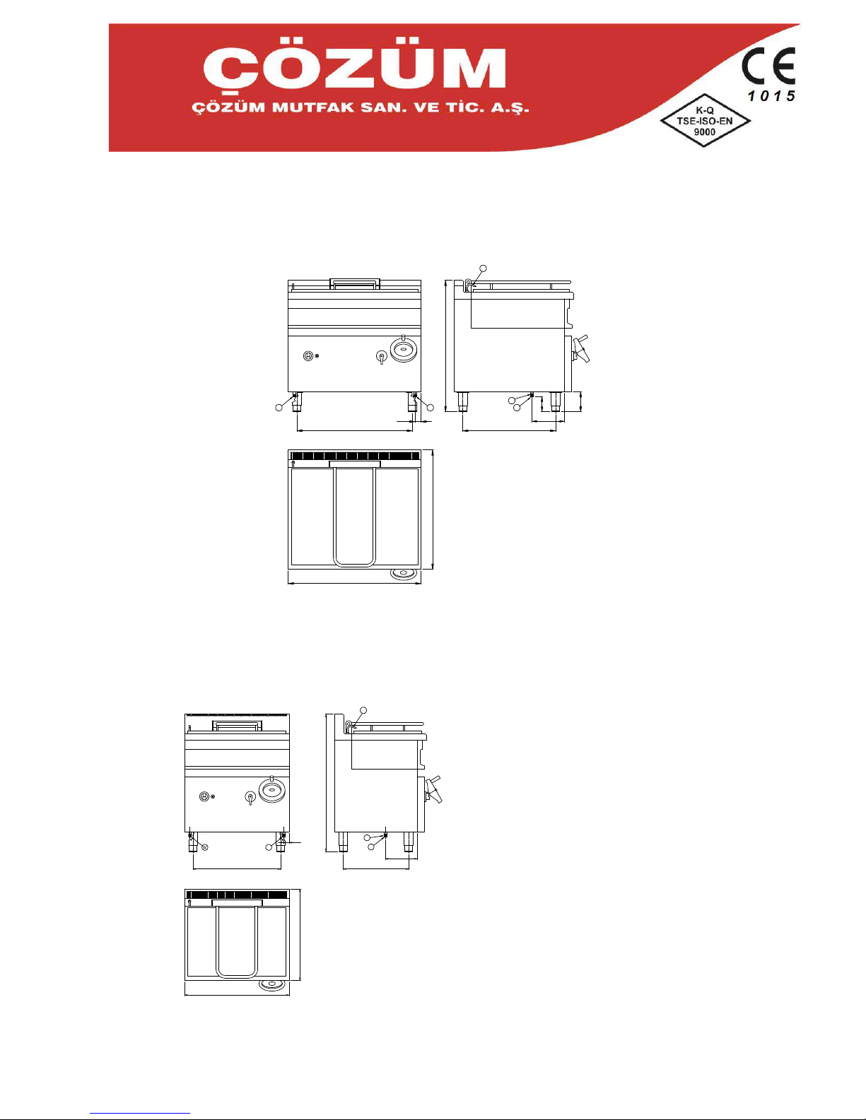
1. Device Specifications
1.1 Technical Specifications
GP922
S-SU ÇIKIŞI (WATER OUTLET)
W-SU GİRİŞİ (WATER İNLET)
G-GAZ BAĞLANTISI
(GAS CONNECTION)
S
W
W
G
242
110
45
G
900
1000
990
150
700870
GP722
1050
G-GAZ BAĞLANTISI
(GAS CONNECTION)
W-SU GİRİŞİ (WATER İNLET)
S-SU ÇIKIŞI (WATER OUTLET)
W
W
S
700
800
500670
G
242
G
42
Sayfa 5/15
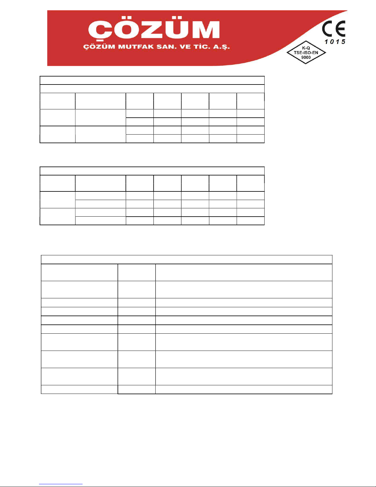
Heat input of one burner
Total heat input
Type
Number of
nozzles
G2020mbar
G2025mbar
G3030mbar
G3050mbar
G3137mbar
GP922
1
20
20 20 20 20 20 20 20 20 20
GP722
1
8,8 8,8 8,8 8,8 8,8
8,8 8,8 8,8 8,8 8,8
Nozzle Diamater
Type
Nozzle diamter
G2020mbar
G2025mbar
G3030mbar
G3050mbar
G3137mbar
GP922
Burner
3 3 2.0 2.0 1.50
Pilot Burner
0,35 0,35 0,25 0,25 0,25
GP722
Burner
2.00 2.00 1.40 1.20 1.40
Pilot Burner
0,35 0,35 0,25 0,25 0,25
Gas Type
Gas
Category
Gas supply
pressure mbar
Country of destination
I
2E
20
DE,LU,PL.RO
I
2E+
20/25
BE,FR
I
3B/P
50
AT,DE,HU
I3+ 28-
30/37
BE,CH.CY,CZ,EE,ES,FR,GB,GR.IE,IT,LT,LV,PT,SI,SK
I I
2E3B/P
20/50
DE
I I
2E+3+
20/25,28
-
30/37
BE,FR
I2H 20
AT,CH,CZ,DK,EE,ES,FI,GB,GR,IE,IT,LT,LV,NO,PT,SE,SI,S
K,RO,BG,TR
I
3B/P
28-30 CY,CZ,DK,EE,FI,GR,HU,IT,LT,LV,MT,NL,NO,SE,SI,SK,RO,
BG,TR
I I
2H3B/P
20,28
-30
CZ,DK,EE,FI,GR,IT,LT,LV,NO,SE,SI,SK,RO,BG,TR
 Loading...