

Coyote Point Systems Equalizer GX Series, Equalizer LX Series Administration Manual
The recognized leader in proven and affordable load
balancing and application delivery solutions
APPLICATION DELIVERY CONTROLLER
EQ/OS 10
Administration Guide
for Equalizer™ LX and GX Series
OS Version 10.3.1
December 23, 2014

Copyright © 2014 Fortinet, Inc. All rights reserved. Fortinet®, FortiGate®, and
FortiGuard® are registered trademarks of Fortinet, Inc., and other Fortinet names herein
may also be trademarks of Fortinet. All other product or company names may be
trademarks of their respective owners. Performance metrics contained herein were
attained in internal lab tests under ideal conditions, and performance may vary. Network
variables, different network environments and other conditions may affect performance
results. Nothing herein represents any binding commitment by Fortinet, and Fortinet
disclaims all warranties, whether express or implied, except to the extent Fortinet enters a
binding written contract, signed by Fortinet’s General Counsel, with a purchaser that
expressly warrants that the identified product will perform according to the performance
metrics herein. For absolute clarity, any such warranty will be limited to performance in the
same ideal conditions as in Fortinet’s internal lab tests. Fortinet disclaims in full any
guarantees. Fortinet reserves the right to change, modify, transfer, or otherwise revise this
publication without notice, and the most current version of the publication shall be
applicable.
Document Version: 10.3.1
Coyote Point Systems
A subsidiary of Fortinet, Inc.
56 Main Street
Millerton, NY 12546

Equalizer Administration Guide
Table of Contents
Table of Contents 3
Introduction 19
About Equalizer 20
Typographical Conventions 21
Attributions 21
Where to Go for More Help 22
Overview 23
Intelligent Load Balancing 24
Real-Time Server Status Information 26
Network Address Translation and Spoofing 27
Load Balancing 29
How a Server is Selected 31
Layer 7 Load Balancing and Server Selection 34
Persistence 35
Why a Server May Not Be Selected 38
What's New 39
What's New in this Revision 40
Installation 43
Hardware Installation 44
UL/cUL & CE/CB Safety Warnings and Precautions 45
Power Requirements 47
Operating Environment 47
Regulatory Certification 47
Setting Up a Terminal or Terminal Emulator 48
Configuring Access 49
Default Login 50
Serial Access 51
First Time Configuration 53
Global Services 54
VLAN Subnet Network Services 56
Copyright © 2014 CoyotePoint Systems, A Subsidiary of Fortinet, Inc.
All Rights Reserved.
3

Table of Contents
First Time VLAN Configuration Example 58
Replacing the Default Certificate, Key, and Cipherspec 61
Sample Configuration 65
Sample Configuration 66
Registering Your Product 73
Registering Your Product 74
Upgrading 77
Upgrade Path from EQ/OS 8.6 to the Latest EQ/OS 10 Version 78
EQ/OS 8.6 Upgrade Procedure 79
Upgrading to the Latest Release 85
Downgrading to EQ/OS 8.6 86
Load Balancing &Networking 89
Networking Technologies 90
Networking Conventions 95
Common Equalizer Networking Scenarios 96
Blank Configuration 96
Single VLAN/Subnet 97
Single VLAN/Subnet with a Default Gateway 99
Dual VLAN/Network 101
Dual VLAN/Network with 2 Gateways 104
Dual VLAN/Network with Outbound NAT 107
Using VLANs 110
How the ADC Routes a Packet 112
Configuring Front Panel Ports 114
Viewing Link Status and Port Settings 115
Viewing Link Status and Port Settings (E350GX, E450GX, E650GX Only) 116
Displaying Port Statistics 118
Source Based Routing Scenarios 119
Source Selection 120
Source Routing Scenarios 121
Spoof Load Balancing Toward Server 122
Spoof Load Balancing Toward Client 124
Non-Spoof Load Balancing Toward Client 125
4 Copyright © 2014 CoyotePoint Systems, A Subsidiary of Fortinet, Inc.

Equalizer Administration Guide
Non Spoof Load Balancing Toward Server 125
Source, Destination Specified 126
Generated by Equalizer 127
Enabling DNS 128
Configuring NTP 129
NTP and Plotting 129
Default NTP Configuration 129
Selecting an NTP Server 130
Managing NTP 131
Source Routing Tables & Rules 132
Source Routing Table 133
IP Filter Rules 134
IP NAT Rules 137
Network Troubleshooting Tools 138
Working in the CLI 139
Starting the CLI 141
Logging In to the CLI Over a Serial Connection 141
Logging In to the CLI Over an SSH Connection 142
Exiting the CLI 143
Working in the CLI 144
CLI Contexts and Objects 144
Object Relationships 146
Command Line Editing 147
Entering Names for Equalizer Objects 148
Using White Space in a Command Line 148
Enabling and Disabling Flags 149
Command Abbreviation and Completion 150
Detection of Invalid Commands and Arguments 151
Specifying Multiple Server Instances 151
Using the no Form of a Command 152
Queued Commands 153
Context Help 155
Global Parameters 156
Show Configuration Command 157
Debug Commands 159
Copyright © 2014 CoyotePoint Systems, A Subsidiary of Fortinet, Inc.
All Rights Reserved.
5

Table of Contents
Context Command Summaries 162
Global Commands 163
Certificate Commands 166
Certificate Revocation List Commands 168
Cluster and Match Rule Commands 169
Diagnostic Commands 177
External Services Commands 178
Failover Commands 180
Firewall Commands 181
GeoCluster and GeoSite Instance Commands 182
GeoSite and GeoSite Resource Commands 185
IP Reputation Commands 187
Interface Commands 188
Interface Command Notes 189
Link Aggregation Commands 191
Link Load Balancing Commands 192
Object List Commands 194
Peer Commands 195
Remote Management Commands 198
Responder Commands 199
Regular Expressions in Redirect Responders 200
Server Commands 201
Server Pool and Server Instance Commands 202
Server Side Encryption Commands 210
Smart Control Commands 211
SNMP Commands 213
Tunnel Commands 215
User Commands 216
User Flags 219
Setting the Locale 219
Creating a User 219
Deleting a User 219
User Passwords 220
User Permissions 220
User Permissions Assigned on Object Creation 222
6 Copyright © 2014 CoyotePoint Systems, A Subsidiary of Fortinet, Inc.

Equalizer Administration Guide
Displaying User Information 222
VLAN and Subnet Commands 223
VLAN and Subnet Command Notes 226
Using the GUI 229
Logging In 230
Navigating Through the Interface 231
Entering Names for Load Balancing Objects 235
Using the WebHelp 236
System Settings 239
Global Settings 240
Dashboard 241
Certificates 243
Installing a Certificate 243
Certificate Revocation Lists 245
Installing a Certificate Revocation List (CRL) 245
IP Reputation 247
Parameters 264
Server Side Encryption 266
Smart Control 267
SNMP 268
MIB Compliance 270
MIB Files 271
External Services 272
SMTP Relay 272
VLB Manager 273
Maintenance 275
Setting Date and Time 275
Backup and Restore 276
Backup 277
Restore 279
Manage Software 282
Tools 283
Network Configuration 286
Interfaces 286
Copyright © 2014 CoyotePoint Systems, A Subsidiary of Fortinet, Inc.
All Rights Reserved.
7

Table of Contents
Interfaces (E350GX, E450GX, E650GX Only) 288
Link Aggregation 291
Configuring VLANs 297
Configuring Subnets 301
About Permitted Subnets 303
Configuring Subnet Destination Routes 304
Configuring Outbound NAT 307
IPv6 Tunnel Overview 309
Configuring an IPv6 Tunnel 310
Failover 312
Working with Clusters and Match Rules 313
Overview of Clusters 315
Cluster Summary 317
Cluster Connection Timeouts 321
Adding and Deleting Clusters 327
Modifying a Layer 4 TCP or UDP Cluster 330
TCP Cluster Configuration Summary 330
TCP Cluster Configuration Settings 331
TCP Cluster Persistence 333
TCP Cluster Timeouts 334
UDP Cluster Configuration Summary 335
UDP Cluster Configuration Settings 336
UDP Cluster Configuration Persistence 338
UDP Cluster Configuration Timeouts 339
UDP Cluster Limitations 340
Modifying a Layer 7 HTTP or HTTPS Cluster 341
Layer 7 Cluster Configuration Summary 342
Layer 7 HTTP and HTTPS Cluster Settings 343
Layer 7 Security Certificate Screen (HTTPS Clusters) 347
Layer 7 SSL Security (HTTPS Clusters) 349
Layer 7 HTTP and HTTPS Cluster Persistence 351
Fallback Persistence Scenarios 355
Server Side Encryption 358
Layer 7 Cluster Reporting 362
Layer 7 Cluster Timeouts 362
8 Copyright © 2014 CoyotePoint Systems, A Subsidiary of Fortinet, Inc.

Equalizer Administration Guide
Server Name Indication 363
Layer 7 TCP Cluster Settings 367
Layer 7 TCP Cluster Persistence 370
Additional Cluster Configuration 371
About Passive FTP Translation 371
Enabling Cookies for Persistent Connections 371
Enabling Persistent Server Connections 371
Enabling Sticky Connections 371
Enabling the Once Only and Persist Options 373
Enabling Both the Once Only and Always Options 376
Enabling Once Only and Compression 376
Enabling Once Only and No Header Rewrite for HTTPS 376
Specifying a Custom Header for HTTP/HTTPS Clusters 377
Performance Considerations for HTTPS Clusters 378
HTTPS Performance and Xcel SSL Acceleration 378
HTTPS Header Injection 380
Providing FTP Services on a Virtual Cluster 380
FTP Cluster Configuration 381
Configuring Direct Server Return 382
Testing Your Basic Configuration 385
Using Match Rules 386
How Match Rules are Processed 387
Match Rule Order 388
Match Rule Expressions and Bodies 389
Match Rule Expressions 390
Match Bodies 391
Match Rule Functions 393
Match Rule Operators 396
Match Rule Definitions 397
Match Rule Expression Examples 397
Match Rule Expression Notes 398
Using Responders in Match Rules 402
Managing Match Rules 402
Copyright © 2014 CoyotePoint Systems, A Subsidiary of Fortinet, Inc.
All Rights Reserved.
9

Table of Contents
Displaying Match Rules 404
Default Match Rule 404
Creating a New Match Rule 404
Modifying a Match Rule 408
Removing a Match Rule 408
Operating within the Expression Editor 410
Parsing the URI Using Match Rules 412
Changing Persistence Settings Using Match Rules 413
Using Persistence with Match Rules 415
Using the Match Rule Expression Editor 409
Example Match Rules 412
Changing the Spoof (SNAT) Setting Using Match Rules 415
Server Selection Based on Content Type Using Match Rules 416
Cluster and Match Rule Statistics and Reporting (CLI and GUI) 420
Server Pools and Server Instances 429
About Server Pools 430
Server Pool Summary 431
Configuring Server Pool Load-Balancing Options 432
Equalizer’s Load Balancing Policies 432
Equalizer’s Load Balancing Response Settings 433
Aggressive Load Balancing 434
Dynamic Weight Oscillations 434
Using Active Content Verification (ACV) 435
Adding and Configuring a Server Pool (GUI) 437
Adding and Configuring a Server Pool (CLI) 439
Adding Server Instances(GUI) 440
Server Instance Summary Screen 443
Adding Server Instances (CLI) 444
Testing ACV on a Server Instance 445
Associate a Server Pool with a Cluster (GUI) 446
Associate a Server Pool with a Cluster (CLI) 447
10 Copyright © 2014 CoyotePoint Systems, A Subsidiary of Fortinet, Inc.

Equalizer Administration Guide
Deleting a Server Pool (GUI) 448
Deleting a Server Pool (CLI) 449
Server Pool and Server Instance Reporting (CLI and GUI) 450
Servers 457
Server Summary 458
Adding and Modifying Servers 460
Server Software Configuration 463
Adjusting a Server’s Initial Weight 464
Setting Initial Weights for Homogenous Clusters 464
Maximum Connections Limits, Responders, and Hot Spares 465
Setting initial Weights for Mixed Clusters 466
Interaction of Server Options and Connection Processing 466
Shutting Down a Server Gracefully 466
Server Configuration Constraints 468
Configuring Routing on Servers 469
Spoof Controls SNAT 469
How Spoof Influences Routing 469
Server Statistics and Reporting (CLI and GUI) 471
Automatic Cluster Responders 477
Automatic Cluster Responders 478
Responder Summary 479
Managing Responders 480
Adding a Responder 480
Modifying a Responder 482
Using Regular Expressions in Redirect Responders 482
Using Responders in Match Rules 485
Creating a Match Rule for a “Sorry Page” 485
Creating a Match Rule to Redirect All Traffic for a Specific URL 487
Responders and Hot Spares 489
Responder Statistics and Reporting (CLI and GUI) 490
Link Load Balancing 493
Link Load Balancing 494
Outbound Link Load Balancing 495
Copyright © 2014 CoyotePoint Systems, A Subsidiary of Fortinet, Inc.
All Rights Reserved.
11

Table of Contents
Configuring Outbound Link Load Balancing 496
Inbound Link Load Balancing 503
Configuring Inbound Link Load Balancing 504
Global Load Balance 511
Overview of Envoy Geographic Load Balancing 512
Envoy Configuration Summary 513
DNSConfiguration 513
Local (Caching) DNSServer 513
Configuring an Authoritative DNSName Server for Envoy 513
Using Envoy with Firewalled Networks 516
Using Envoy with NAT Devices 516
Configuring GeoClusters 517
Configuring GeoSites 522
GeoSite Instance Parameters 523
GeoSite Resources and GeoSite Instance Resources 527
Failover 531
Understanding Failover 532
How the Load Balancer Determines if it Should Assume the Primary Role 533
Releases Supported for Failover with EQ/OS 10 534
Guidelines for Updating a Failover Pair 535
Failover Between Two EQ/OS 10 Systems 536
Types of Failover Configurations 536
Peer Failover Modes 538
Failover Constraints 539
Configuration Synchronization Constraints 541
Server / Gateway Availability Constraint 543
Failover Peer Probes and Timeouts 543
Peer, Interface, Subnet States and Substates 545
Failover Between EQ/OS 8.6 and EQ/OS 10 546
Guidelines for Upgrading a Failover Pair from EQ/OS 8.6 to EQ/OS 10 546
EQ/OS 8.6 Failover Constraints 546
Server Availability Constraint 547
Enable Failover of EQ/OS 8.6 to EQ/OS 10 548
Configuring Active/Passive Failover Between Two Systems 555
12 Copyright © 2014 CoyotePoint Systems, A Subsidiary of Fortinet, Inc.

Equalizer Administration Guide
Configuring VLAN (Subnet) Failover Settings (CLI) 556
Configuring VLAN (Subnet) Failover Settings (GUI) 559
Configuring Active/Passive Failover (CLI) 562
Configuring Active/Passive Failover (GUI) 572
Configuring Active/Active Failover 577
Failover Groups 577
Configuring Active/Active Failover (CLI) 578
Configuring N+1 Failover 583
Network Design for N+1 Failover 584
How a Peer is Chosen for Failover in N+1 Configuration 584
Monitoring N+1 Failover 586
Rebalancing 590
Configuring N + 1 Failover with 3 Load Balancers (CLI) 591
Configuring N + 1 Failover with 4 Load Balancers (CLI) 597
Configuring N + 0 Failover with 4 Load Balancers (CLI) 605
Logs and Reports 615
Displaying Logs 616
Export to CSV 617
Filtering Status Details 618
Event Log 619
System Log 620
Audit Log 621
Upgrade Log 622
Remote System Logging 623
Reporting 625
Configuring Server Connections 627
HTTP Multiplexing 628
Enabling HTTP Multiplexing 629
Disabling "spoof" for HTTP Multiplexing 630
Server Options for HTTP Multiplexing 631
Direct Server Return (DSR) 632
Configuring a Cluster for Direct Server Return 633
Configuring Servers for Direct Server Return 634
Configuring Windows Server 2003 and IIS for DSR 634
Copyright © 2014 CoyotePoint Systems, A Subsidiary of Fortinet, Inc.
All Rights Reserved.
13

Table of Contents
Adjusting ARP Behavior on Linux Servers 635
Configuring a Linux System running Apache for DSR 635
Configuring a Loopback Interface on Other Systems for DSR 636
Weak and Strong Host Models and DSR 637
Server Health Check Probes 639
About Server Health Check Probes 640
Layer 3 ICMP Probes 641
Enabling/Disabling Layer 3 ICMP Probes 642
Configuring Layer 3 ICMP Probe Parameters 643
L4 UDP Probes 645
Enabling/Disabling L4 UDP Probes 645
L4 TCP/IP Probes 646
Enabling/Disabling L4 TCP Probes 646
Active Content Verification (ACV) Probes 647
Enabling/Disabling ACV Probes 648
Setting ACV Query and Response Strings 649
Testing ACV Probes 650
Configuring UDP and TCP Parameters 651
Simple Health Check Probes 653
Configuring Simple Health Check Probe Parameters 653
Simple Health Checks and Load Balancing Policies 658
Server Agents 659
Sample Server Agent 660
VLB Health Check Probes 662
Enabling/Disabling VLB Health Check Probes 663
Configuring VLB Health Check Probe Parameters 664
Health Check Timeouts 675
Smart Control 679
Smart Control Overview 680
Why PHP? 680
How Smart Control Works 681
Smart Control Types 682
Smart Control Configuration Guidelines 683
Smart Control Classes 684
14 Copyright © 2014 CoyotePoint Systems, A Subsidiary of Fortinet, Inc.

Equalizer Administration Guide
Server Pool Class (srvpool) 685
Server Class (server) 689
Server Instance Class (si) 692
ADC Class (adc) 695
Sample Trigger Script for the Configuration of Multiple Hot Spare Servers 697
Sample Trigger Script for Rebooting the System 698
Adding Smart Controls 699
Alerts 713
Alert Notification Types 714
Configuring Alerts 715
Configuring an SMTP Relay 716
Configuring Alerts in the CLI 718
Configuring Alerts in the GUI 721
Using SNMP Traps 725
Setting Up SNMP Traps 726
Setting Up an SNMP Management Station 727
Enabling SNMP 728
Enabling SNMP Traps 729
Creating Alerts for SNMP Traps 730
User and Group Management 733
Best User and Group Management Practices 734
Object Permission Types 735
Required Task Permissions and Flags 736
Single and Multiple User Scenarios 742
How to Use Regular Expressions 747
Regular Expression Terms 748
Learning About Atoms 749
Creating a Bracket Expression 750
Escape Sequences 751
Matching in Regular Expressions 752
Using Regular Expressions in Responders 753
Troubleshooting 755
Connectivity and Configuration Issues 756
Copyright © 2014 CoyotePoint Systems, A Subsidiary of Fortinet, Inc.
All Rights Reserved.
15

Table of Contents
Using Diagnostic Commands 759
Using tcpdump 772
Using Watchdog Timers 776
Configuring the Baseboard Management Controller (BMC) 780
Prerequisites 780
Configuration 780
Using IPMI to Power Servers On/Off 788
Equalizer OnDemand 791
What is Equalizer OnDemand? 792
Differences from Equalizer Hardware 793
Installing and Upgrading Equalizer OnDemand 796
VMware Host Requirements 796
Installing EQOD Using OVF 797
Installing EQOD from a ZIP file 799
VMware vSphere or vCenter Clients 799
VMware Player and VMware Fusion 800
Licensing EQOD 801
Upgrading EQOD 803
Using Certificates in HTTPS Clusters 805
Using Certificates in HTTPS Clusters 806
Configuring Cipher Suites 811
Enabling HTTPS with a Server Certificate 817
Enabling HTTPS with Server and Client Certificates 818
Generating a CSR and Getting It Signed by a CA 820
Generating a Self-Signed Certificate 822
Installing Certificates for an HTTPS Cluster 823
Converting a Certificate from PEM to PKCS12 Format 824
Using the File Editor 825
Editing Files 826
EQ/OS 8.6 to EQ/OS 10.0 Configuration Converter 829
EQ/OS 8.6 to EQ/OS 10 Configuration Conversion Process 830
Port Numbers 839
Port Numbers 840
16 Copyright © 2014 CoyotePoint Systems, A Subsidiary of Fortinet, Inc.

Equalizer Administration Guide
Networking TranslationBetween EQ/OS 10.1.x and 10.2.x 843
Networking Translation Between 10.1.x and 10.2.x Systems 844
Maximum Configuration Values 848
Glossary 849
Copyright © 2014 CoyotePoint Systems, A Subsidiary of Fortinet, Inc.
All Rights Reserved.
17


Equalizer Administration Guide
Chapter 1
Introduction
Subsections in this chapter include:
About Equalizer 20
Typographical Conventions 21
Attributions 21
Where to Go for More Help 22
Copyright © 2014 CoyotePoint Systems, A Subsidiary of Fortinet, Inc.
All Rights Reserved.
19

Introduction
About Equalizer
The Equalizer Application Delivery Controller (ADC) is a high-performance switch that offers
optimized availability, user experience, and performance of mobile, cloud-based and enterprise
applications while increasing server efficiency and reducing cost and complexity in the data
center. It features:
l Intelligent load balancing based on multiple, user-configurable criteria
l Non-stop availability with no single point of failure, through the use of redundant servers in
a cluster and the optional addition of a failover (or backup) Equalizer
l Layer 7 content-sensitive routing
l Connection persistence using cookies or IP addresses
l Real-time server and cluster performance monitoring
l Server and cluster administration from a single interface
l SSL acceleration (on Equalizer models with Xcel SSL Hardware Acceleration)
l Data compression (on Equalizer models with Express Hardware GZIP Compression)
l Geographic load balancing
20 Copyright © 2014 CoyotePoint Systems, A Subsidiary of Fortinet, Inc.

Equalizer Administration Guide
Typographical Conventions
The following typographical conventions appear throughout this guide:
l Text in “double quotes” indicates the introduction of a new term.
l Italic text is used primarily to indicate variables in command lines, and is also used to
emphasize concepts while discussing Equalizer operation.
l Boldface text highlights GUI interface screen elements: labels, buttons, tabs, icons, etc., as
well as data the user must type into a GUI element.
l Courier text denotes computer output: messages, commands, file names, directory
names, keywords, and syntax exactly as displayed by the system.
l Bold courier text is text the user must type at the CLI prompt. Bold courier text in brack-
ets -- indicates a keyboard key or key sequence that must be typed.
l Bold text sequences such as “Cluster > Configuration > Set tings” are used to indicate the GUI con-
trols a user needs to click to display the GUI form relevant to the task at hand. In the above
example, the user would click on the Equalizer host name displayed at the top of the left navigational tree , click on the Configuration tab in the right pane, and then click on the Set tings
tab.
1. Numbered lists show steps that you must complete in the numbered order.
l Bulleted lists identify items that you can address in any order.
Note - A note box in the margin cites the source of information or provides a brief explanation that supports a specific
statement but is not integral to the logical flow of the text.
The symbol on the left emphasizes a critical note or caution.
Attributions
Many of the icons used in the Web UI and reproduced in this manual are © Copyright 2013
FatCow Web Hosting. All rights reserved. These icons are licensed under a Creative Commons
Attribution 3.0 License (http://creativecommons.org/licenses/by/3.0/us/) and are used without
modification.
Copyright © 2014 CoyotePoint Systems, A Subsidiary of Fortinet, Inc.
All Rights Reserved.
21

Introduction
Where to Go for More Help
These instructions are part of the product documentation delivered with Equalizer’s browserbased GUI. You can display the appropriate manual section for any interface screen by selecting
Help > Context help from the menu at the top of the interface. The Help menu also contains links to
the Release Notes for the currently running software version, and other documentation.
Hard copy documentation provided with every Equalizer includes the Quick Start Guide and the
Basic Configuration Guide. These two documents are designed to help you get Equalizer out of the
box and working with your first virtual clusters. The Basic Configuration Guide also contains a
Resource CD with copies of all product documentation, including support documents that help you
configure Equalizer for a variety of environments.
Register today to get access to the Fortinet Support Portal:
https://support.fortinet.com
Registration provides you with a login so you can access these benefits:
l Support FAQs: answers to our customer's most common questions.
l Moderated Customer Support Forum: ask questions and get answers from our support staff
and other Equalizer users.
l Software upgrades and security patches: access to the latest software updates to keep your
Equalizer current and secure.
l Online device manuals, supplements, and release notes: the latest Equalizer documentation
and updates.
l Links to additional resources, and more.
Registration details can be found in "Registering Your Product" on page 74.
22 Copyright © 2014 CoyotePoint Systems, A Subsidiary of Fortinet, Inc.

Equalizer Administration Guide
Chapter 2
Overview
Sections within this chapter include:
Intelligent Load Balancing 24
Real-Time Server Status Information 26
Network Address Translation and Spoofing 27
Load Balancing 29
How a Server is Selected 31
Layer 7 Load Balancing and Server Selection 34
Persistence 35
Why a Server May Not Be Selected 38
Copyright © 2014 CoyotePoint Systems, A Subsidiary of Fortinet, Inc.
All Rights Reserved.
23
Overview
Intelligent Load Balancing
The Equalizer appliance functions as a gateway to one or more sets of servers organized into
virtual clusters. When a client submits a request to a site that the appliance manages, it identifies
the virtual cluster for which the request is intended, determines the server in the cluster that will
be best able to handle the request, and forwards the request to that server for processing.
To route the request, the appliance modifies the header of the request packet with the appropriate
server information and forwards the modified packet to the selected server. Depending on the
cluster options chosen, it may also modify the headers in server responses on the way back to the
client.
Equalizer supports clusters that route requests based on either Layer 4 (TCP or UDP) or Layer 7
(HTTP or HTTPS) protocols. Layer 4 is also referred to as the Transport Layer, while Layer 7 is
referred to as the Application Layer. These terms come from the OSI and TCP/IP Reference
Models, abstract models for network protocol design.
In general, Layer 4 clusters are intended for configurations where routing by the destination IP
address of the request is sufficient and no examination of the request headers is required. Layer 7
clusters are intended for configurations where routing decisions need to be made based on the
content of the request headers. the appliance evaluates and can modify the content of request
headers as it routes packets to servers; in some cases, it can also modify headers in server
responses on their way back to the client.
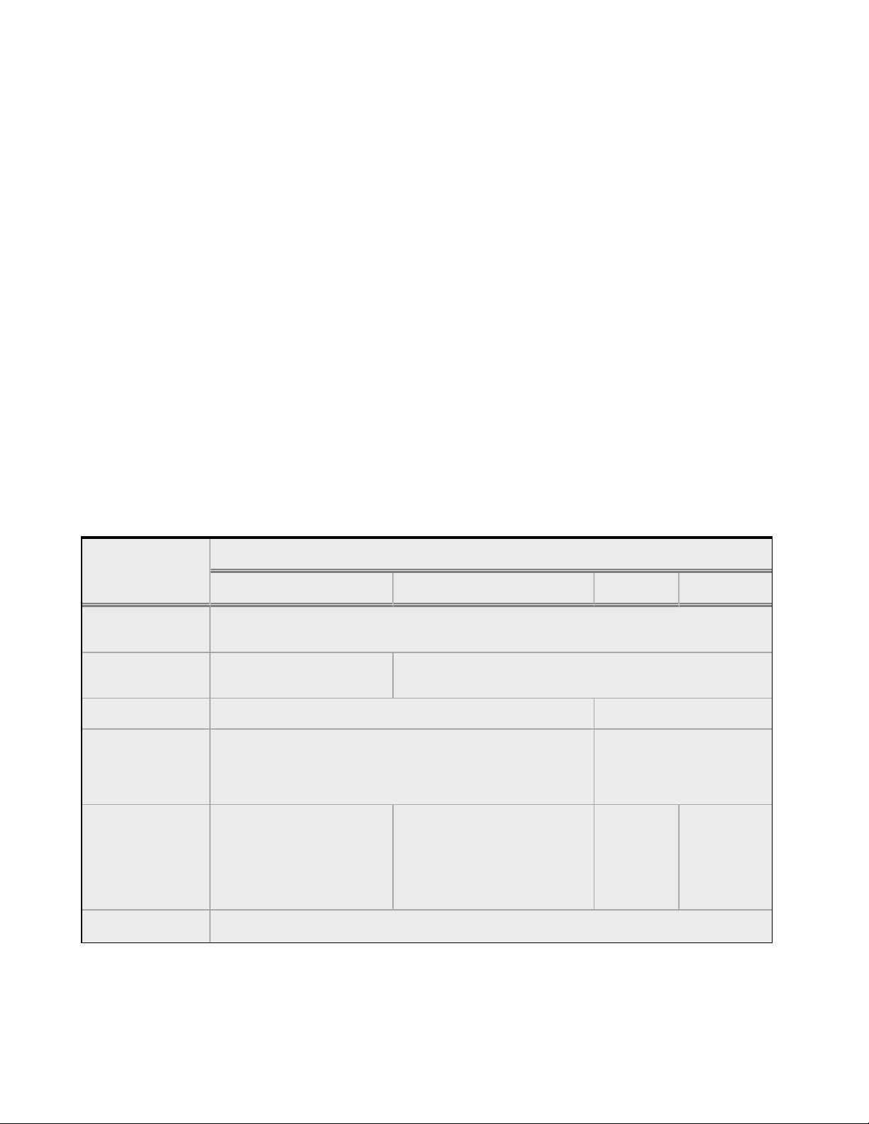
Basic Capabilities of Cluster Types Supported by Equalizer
Cluster Type
Feature
L4 UDP L4, L7 TCP L7 HTTP L7 HTTPS
Load balancing
policies
Server failure
detection (probes)
Persistence Based on IP Using Cookies
Server selection by
request content
(i.e., Match Rules)
Load balanced
protocols
NAT and spoofing
ICMP, TCP, Health Check ICMP, TCP, ACV, Health Check
No; load is balanced according to current load balancing policy.
Ideal for stateless UDP-
based protocols, such as
DNS and RADIUS; WAP
gateways; NFS server
clusters that provide a
single-system image.
Round Robin, Static Weight, Adaptive, Fastest response,
Least Connections, Server Agent, Custom
Yes; load is balanced
according to decisions
made by examining request
Ideal for stateful TCP-based
protocols, such as HTTP,
HTTPS, SMTP, FTP,
LDAP/LDAPS
and others.
HTTP HTTPS
Yes
content.
24 Copyright © 2014 CoyotePoint Systems, A Subsidiary of Fortinet, Inc.

Equalizer Administration Guide
Regardless of cluster type, the appliance uses intelligent load balancing algorithms to determine
the best server to receive a request. These algorithms take into account the configuration options
set for the cluster and servers, real-time server status information, and information from the
request itself. For Layer 7 clusters, user-defined match rules can also be used to determine the
route a packet should take.
Copyright © 2014 CoyotePoint Systems, A Subsidiary of Fortinet, Inc.
All Rights Reserved.
25

Overview
Real-Time Server Status Information
Equalizer gathers real-time information about a server’s status using ICMP Probes, TCP Probes,
Active Content Verification (ACV), and Server Agents. ICMP and TCP Probes are the default
probing methods.
ICMP Probes use Internet Control Message Protocol to send an "Echo request" to the server, and
then wait for the server to respond with an ICMP "Echo reply" message (i.e., the Unix ping
command). ICMP is a Layer 3 protocol. ICMP probes can be disabled via a global flag.
TCP Probes establish (and tear down) a TCP connection between the appliance and the server in a
typical Layer 4 exchange of TCP SYN, ACK, and FIN packets. If the connection cannot be
completed, the appliance considers the server down and stops routing requests to it. TCP probes
cannot be disabled.
Active Content Verification (ACV) provides an optional method for checking the validity of a
server’s response using Layer 7 network services that support a text-based request/response
protocol, such as HTTP. When you enable ACV for a cluster, the appliance requests data from each
server in the cluster (using an ACV Probe string)and verifies the returned data (against anACV
Response string). If it receives no response or the response string is not in the response, the
verification fails and it stops routing new requests to that server. See Active Content Verification
(ACV) Probes for more information.
Note - ACV is not supported for Layer 4 UDP clusters.
Server Agent Probes enable the appliance to communicate with a user-written program (the
agent) running on the server. A server agent is written to open a server port and, when the
appliance connects to the port, the server agent responds with an indication of the current server
load and performance. This enables adjustment of the dynamic weights of the server according to
detailed performance measurements performed by the agent, based on any metrics available on
the server. If the server is overloaded and you have enabled server agent load balancing, the
appliance reduces the server’s dynamic weight so that the server receives fewer requests. The
interface between the appliance and server agents is simple and well-defined. Agents can be
written in any language supported on the server (e.g., perl, C, shell script, javascript, etc.). See
Simple Health Checks and Load Balancing Policies for more information.
For those who have one or more VMware ESX Servers, VLB can be configured to use VMware’s
status reporting to determine server status, and can also be configured to automatically manage
VMware servers based on status information obtained from VMware.
26 Copyright © 2014 CoyotePoint Systems, A Subsidiary of Fortinet, Inc.

Equalizer Administration Guide
Network Address Translation and Spoofing
The servers load balanced by Equalizer provide applications or services on specific IP addresses
and ports, and are organized into virtual clusters, each with its own IP address. Clients send
requests to the cluster IP addresses on the appliance instead of sending them to the IP addresses
of the servers.
Central to the operation of any load balancer is the Network Address Translation (NAT)
subsystem. On Equalizer, NAT is used as follows:
1. When Equalizer receives a client packet, it always translates the destination IP (the cluster
IP) to the IP address of one of the server instances in a server pool. The server IP used is
determined by the cluster’s load balancing settings.
2. Depending on the setting of the cluster spoof option, Equalizer may also perform Source
NAT, or SNAT.
When the spoof option is enabled on a cluster, then SNAT is disabled: the NAT subsystem
leaves the client IP address as the source IP address in the packet it forwards to the server.
For this reason, the servers in a cluster with spoof enabled are usually configured to use
Equalizer’s IP address as their default gateway to ensure that all responses go through the
appliance (otherwise, the server would attempt to respond directly to the client IP).
When the spoof option is disabled on a cluster, then SNAT is enabled. Equalizer translates
the source IP (the client IP) to one of the appliance’s IP addresses before forwarding packets to a server. The servers will send responses back to the appliance’s IP (so it is usually
not necessary to set the appliance as the default gateway on the servers when spoof is disabled).
Match rules can be used to selectively apply the spoof option to client requests. This is sometimes called selective SNAT. See "Creating a New Match Rule" on page 404.
3. When a server sends a response to a client request through Equalizer, the NAT subsystem
always translates the source IP in the response packets (that is, the server IP) to the cluster
IP to which the client originally sent the request. This is necessary since the client sent its
original request to the cluster IP and will not recognize the server’s IP address as a
response to its request -- instead, it will drop the packet.
Copyright © 2014 CoyotePoint Systems, A Subsidiary of Fortinet, Inc.
All Rights Reserved.
27
Overview
4. NAT can also be enabled for packets that originate on the servers behind Equalizer and are
destined for subnets other than the subnet on which the servers reside -- on the appliance,
this is called outbound NAT. This is usually required in dual network mode when reserved IP
addresses (e.g., 10.x.x.x, 192.168.x.x) are being used on the internal interface, so that the
recipients do not see reserved IP addresses in packets originating from the servers. When
the global outbound NAT option is enabled, the appliance translates the source IP in packets
from the servers that are not part of a client connection to the the appliance’s Default VLAN
IP address (the external interface IP address on the E250GX and legacy ‘si’ systems), or to
the address specified in the server’s Out bound NAT tab. Enabling outbound NAT, as a result,
has a performance cost since the appliance is examining every outbound packet.
Note - When Equalizer is in single network mode, outbound NAT should be disabled. Since Equalizer resides on a
single subnet, outbound NAT is not needed, and may cause unexpected behavior.
When Equalizer receives a packet that is not destined for a virtual cluster IP address, a failover IP
address, a client IP address on an open connection, or one of its own IP addresses, the appliance
passes the packet through to the destination network unaltered.
28 Copyright © 2014 CoyotePoint Systems, A Subsidiary of Fortinet, Inc.
Equalizer Administration Guide
Load Balancing
Load balancing is based on the policy selected. The policies can be split up into two categories:
1. round robin
2. everything else
Round robin simply selects the next server in the list with no regard for how busy that server may
be.
Other load balancing policies use proprietary algorithms to compute the load of a server and then
select the server with the least load server.
Although the load balancing policies are proprietary, they use the following factors in their
calculation:
l Active connections - The number of connections a server currently has active and the number
of connections that it tends to have open.
l Connection latency - The amount of time that it takes a server to respond to a client request.
l Health check performance values - Depending on the health checks configured, this may be not
used at all, or it can completely define how the load is calculated.
Once a load is calculated, Equalizer distributes incoming requests using the relative loads as
weights.
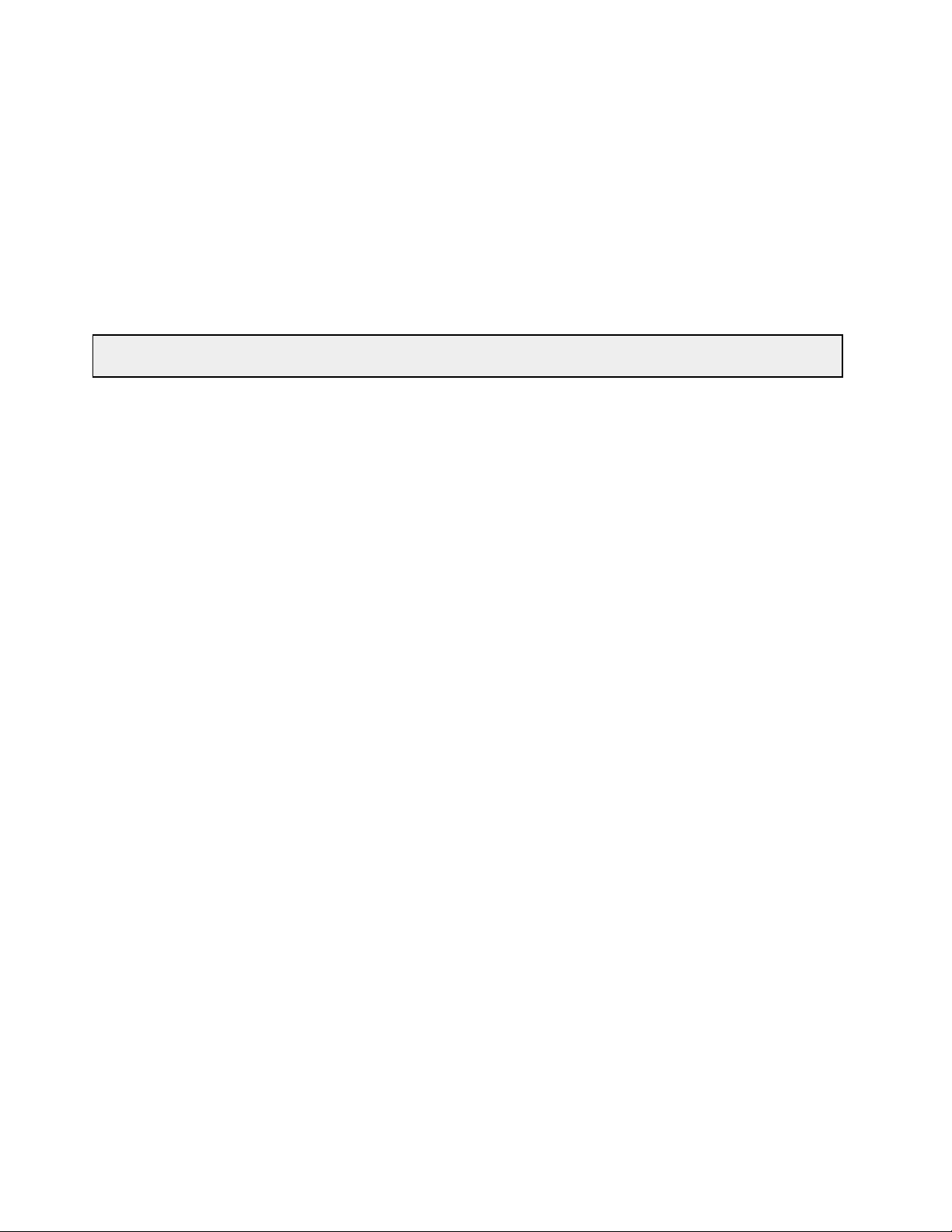
sv00
Load = 50
sv01
Load = 50
sv02
Load = 50
Equalizer calculated loads, so the request distribution will be approximately equal
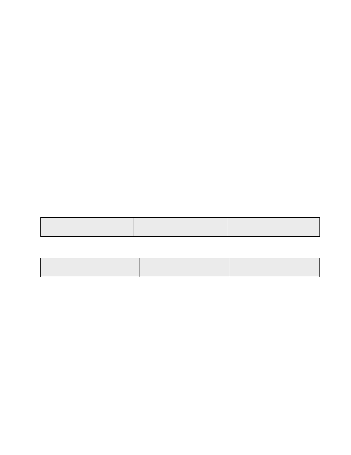
sv00
Load = 100
sv01
Load = 50
sv02
Load = 25
sv01 and sv02 above are uneven loads. sv01 is twice as loaded as sv02, so it will receive about
half the requests.
The load calculations happen approximately every 10 seconds and server weights are adjusted
accordingly. During that 10 second interval, the relative server loads remain the same, but probe
and health check information is collected about the servers so that it can be used for the next
calculation.
The load calculation works the same for Layer 4 and Layer 7 clusters (at the server-pool level –
and these can be shared between all cluster types).
Copyright © 2014 CoyotePoint Systems, A Subsidiary of Fortinet, Inc.
All Rights Reserved.
29

Overview
There are two additional variables for load balancing:
l Hot spare - if a server instance (in a server pool) is marked as a Hot Spare, it is not included in
the pool of servers to select from unless every other non-hot-spare server is down. If a connection persists to this server, it will be placed back on this server.
l Quiesce - If a server instance (in a server pool) has been marked as Quiesce, it will not be
included in the pool of servers to select from. Only previously existing (persistent) connections will be made to this server.
30 Copyright © 2014 CoyotePoint Systems, A Subsidiary of Fortinet, Inc.
 Loading...