

Coyote Point Systems E350GX, E450GX, E650GX Installation And Administration Manual

Equalizer
Installation and
Administration Guide
Version 8.6
October 2010
Coyote Point Systems, Inc.
San Jose, California 95112
675 North First Street
Suite 975

Copyright © 1997-2010 Coyote Point Systems Inc.
All Rights Reserved.
The following are Trademarks or Registered Trademarks of Coyote Point Systems Incorporated in
the United States and other countries:
Coyote Point™
Equalizer
®
Equalizer VLB™
Envoy
®
Equalizer Extreme™
Equalizer Extreme II™
Xcel™
Express™
Emissary™
E250si™
E350si™
E450si™
E550si™
E650si™
E250
GX™
E350
GX™
E450
GX™
E650
GX™
All other brand or product names used in this document are trademarks or registered trademarks of
their respective companies or organizations.
THE SPECIFICATIONS AND INFORMATION REGARDING THE PRODUCTS IN THIS
MANUAL ARE SUBJECT TO CHANGE WITHOUT NOTICE. ALL STATEMENTS,
INFORMATION, AND RECOMMENDATIONS IN THIS MANUAL ARE BELIEVED TO BE
ACCURATE BUT ARE PRESENTED WITHOUT WARRANTY OF ANY KIND, EXPRESS OR
IMPLIED. USERS MUST TAKE FULL RESPONSIBILITY FOR THEIR APPLICATION OF
ANY PRODUCTS.
This document was revised for Equalizer Software Version 8.6.0b.

Contents
Preface 15
In This Guide .................................................................................................................15
Typographical Conventions ...........................................................................................16
Where to Go for More Help ...........................................................................................17
Equalizer Overview 19
Introducing Equalizer .....................................................................................................20
Intelligent Load Balancing ......................................................................................20
Load Balancing Configuration ................................................................................21
Real-Time Server Status Information .....................................................................21
Network Address Translation and Spoofing ...........................................................22
Maintaining Persistent Sessions and Connections ................................................23
Cookie-Based Persistence (Layer 7) ....................................................................................... 23
IP-Address Based Persistence (Layer 4)................................................................................. 24
Is Connection Persistence Always Needed With Session Persistence? ................................. 24
Layer 7 Load Balancing and Server Selection .......................................................24
Geographic Load Balancing ...................................................................................25
Geographic Load Balancing Routing ....................................................................................... 26
Distributing the Geographic Load ............................................................................................ 26
Adding Equalizer to Your Network .................................................................................29
Equalizer E250GX Network Configuration .............................................................29
Using Equalizer E250GX in a Single Network Environment.................................................... 30
Using Equalizer E250GX in a Dual Network Environment ...................................................... 31
Equalizer E350GX, E450GX, E650GX Network Configuration ..............................32
Using Equalizer E350/450/650GX in a Single VLAN Environment.......................................... 33
Using Equalizer E350/450/650GX in a Dual VLAN Environment ............................................ 34
Using Equalizer E350/450/650GX in a Complex VLAN Environment ..................................... 35
Link Aggregation ....................................................................................................36
Using a Second Equalizer as a Backup Unit ..........................................................36
Where Do I Go Next? ....................................................................................................37
Equalizer Installation and Administration Guide 3

Table of Contents
Installing and Configuring Equalizer Hardware 39
Before You Turn Equalizer On for the First Time ..........................................................40
Stepping Through the Hardware Installation .................................................................40
Setting Up a Terminal or Terminal Emulator .................................................................41
Serial Connection ...................................................................................................41
Performing Basic Equalizer Configuration .....................................................................41
Starting to Configure Equalizer ..............................................................................42
Configuring External and Internal Interfaces on E250GX ......................................42
Configuring the Default VLAN on E350/450/650GX ...............................................43
Setting the Time Zone ............................................................................................44
Setting the Date and Time ......................................................................................44
Adding Administrative Interface Logins ..................................................................44
Changing Equalizer’s Console Password ..............................................................45
Upgrading Equalizer Software ................................................................................45
Shutting Down Equalizer ........................................................................................46
Adding Alternate DNS Servers ...............................................................................46
Managing Remote Access to the Equalizer ...................................................................47
Managing the Remote Access Account .................................................................47
Using the Remote Access Account ........................................................................47
Configuring a Second Equalizer As a Backup (Failover) ...............................................48
Configuring DNS and Firewalls for Envoy .....................................................................48
Configuring the Authoritative Name Server to Query Envoy ..................................48
Using Geographic Load Balancing with Firewalls ..................................................48
Testing Basic Connectivity ............................................................................................49
Using the Administration Interface 51
Logging In and Navigating the Administrative Interface ................................................52
Logging In ...............................................................................................................52
Navigating Through the Interface ...........................................................................53
Managing Access to Equalizer ......................................................................................55
Viewing and Changing GUI and SSH Access ........................................................55
Updating the Administration Interface Certificate ..........................................................56
Managing Multiple Interface Users ................................................................................56
Objects and Permissions ........................................................................................57
Viewing or Modifying Login Permissions ................................................................59
Adding a Login .......................................................................................................60
Deleting a Login .....................................................................................................61
Entering Names for Equalizer Objects ..........................................................................61
4 Equalizer Installation and Administration Guide

Equalizer Network Configuration 63
VLAN Basics ..................................................................................................................64
Configuring VLANs on Equalizer ................................................................................... 65
Configuring VLANs Using the VLAN Wizard ..........................................................66
Adding a VLAN Using the Add VLAN Command ...................................................67
Modifying a VLAN ...................................................................................................68
Deleting a VLAN .....................................................................................................70
Managing Gigabit Switch Ports .....................................................................................71
Switch Administration Interface .............................................................................. 72
Viewing Link Status ................................................................................................................. 72
Viewing Current Port Settings.................................................................................................. 72
Editing Port Settings ................................................................................................................ 73
Commiting and Applying Switch Port Configuration Changes ................................................. 74
Switch Interface Usage Scenarios .........................................................................75
Resetting the Front-Panel Switch ...........................................................................75
Switch Interface Notes for Pre-GX Equalizer Hardware .........................................75
Configuring Static Routes .............................................................................................. 76
Adding a Static Route .............................................................................................76
Modifying a Static Route ........................................................................................77
Deleting a Static Route ...........................................................................................77
Configuring Servers on Your Network ...........................................................................78
Configuring Routing on Servers .............................................................................78
Server Configuration Constraints ...........................................................................78
Configuring Equalizer Operation 81
Licensing Equalizer .......................................................................................................82
Requesting a License Online ................................................................................. 82
Requesting a License Offline .................................................................................84
Modifying Global Parameters ........................................................................................85
Global Probe Parameters .......................................................................................85
Global Networking Parameters ..............................................................................87
Setting Up a Failover Configuration ...............................................................................90
Failover Partition .................................................................................................... 90
Failover Between Different Hardware & Software Versions ...................................91
Using Version 8.6 with Version 8.5.1 and GX/‘si’ Hardware.................................................... 91
Using a GX and an ‘si’ in Failover with Version 8.6 ................................................................. 92
Setting Up or Modifying Failover Using the Failover Wizard ..................................92
Enabling Failover Using the Failover Tabs .............................................................94
Manually Enabling Failover...................................................................................................... 94
Modifying the Failover Configuration ......................................................................99
Equalizer Installation and Administration Guide 5

Table of Contents
Disabling the Failover Configuration ......................................................................99
Re-enabling Failover After Disabling ....................................................................100
Clearing the Failover Configuration ......................................................................101
Modifying VLANs with Failover Configured ..........................................................101
Changing from a Multi-VLAN to a Single-VLAN Network Configuration ................................ 101
Managing System Time and NTP ................................................................................103
NTP and Plotting ..................................................................................................103
Selecting an NTP Server ......................................................................................104
General System Maintenance .....................................................................................106
Saving or Restoring Your Configuration ...............................................................106
Using a Backup Archive Created on Another Equalizer......................................................... 106
Backing Up Your Configuration.............................................................................................. 106
Restoring a Saved Configuration ........................................................................................... 107
Shutting Down Equalizer ......................................................................................107
Rebooting Equalizer .............................................................................................107
Creating a System Information Archive ................................................................108
Upgrading Equalizer Software ..............................................................................108
Administering Virtual Clusters 111
Working with Virtual Clusters .......................................................................................112
Adding a Layer 7 Virtual Cluster ...........................................................................113
Modifying a Layer 7 Virtual Cluster ......................................................................114
Layer 7 Required Tab ............................................................................................................ 114
Layer 7 Probes Tab................................................................................................................ 115
Layer 7 Persistence Tab ........................................................................................................ 116
LB Policy Tab ......................................................................................................................... 117
Layer 7 Networking Tab ......................................................................................................... 118
Layer 7 Security > Certificates Tab (HTTPS only) ................................................................. 119
Layer 7 Security > SSL Tab (HTTPS only) ............................................................................ 120
Adding a Layer 4 Virtual Cluster ...........................................................................121
Modifying a Layer 4 Virtual Cluster ......................................................................122
Layer 4 Required Tab ............................................................................................................ 122
Layer 4 Probes Tab................................................................................................................ 124
Layer 4 Persistence Tab ........................................................................................................ 125
LB Policy Tab ......................................................................................................................... 125
Deleting a Virtual Cluster ......................................................................................126
Copying an Existing Virtual Cluster ......................................................................126
Configuring a Cluster’s Load-Balancing Options .........................................................127
Equalizer’s Load Balancing Policies .....................................................................127
Equalizer’s Load Balancing Response Settings..................................................................... 128
Aggressive Load Balancing.................................................................................................... 128
Dynamic Weight Oscillations.................................................................................................. 128
6 Equalizer Installation and Administration Guide

Configuring a Cluster to Use Server Agents ........................................................128
Enabling Persistent Server Connections ..............................................................129
Enabling Sticky Connections ................................................................................................. 129
Enabling Cookies for Persistent Connections........................................................................ 130
Enabling the Once Only and Persist Options ....................................................... 131
Enabling Both the Once Only and Always Options................................................................ 133
Enabling Once Only and No Header Rewrite for HTTPS .....................................133
Enabling Once Only and Compression ................................................................134
Using Active Content Verification (ACV) ..............................................................134
Using ACV ............................................................................................................................. 134
Enabling ACV ........................................................................................................................ 135
HTTPS Header Insertion ......................................................................................136
Specifying a Custom Header for HTTPS Clusters ............................................... 136
Performance Considerations for HTTPS Clusters ................................................137
HTTPS Performance and Xcel SSL Acceleration .................................................................. 137
Providing FTP Services on a Virtual Cluster ........................................................138
FTP Cluster Configuration ..................................................................................................... 138
Managing Servers ....................................................................................................... 140
The Server Table ..................................................................................................140
Server Software Configuration .............................................................................141
Adding a Server to a Cluster ................................................................................142
Modifying a Server ...............................................................................................144
Configuring Outbound NAT .................................................................................. 145
Enabling Outbound NAT........................................................................................................ 146
Configuring Outbound NAT for a Server................................................................................ 146
Using Outbound NAT on a Server IP in Multiple Clusters ..................................................... 147
Adjusting a Server’s Initial Weight ........................................................................147
Setting initial Weights for Homogenous Clusters................................................................... 147
Setting initial Weights for Mixed Clusters .............................................................................. 148
Setting Maximum Connections per Server ...........................................................148
Maximum Connections Limits, Responders, and Hot Spares ............................................... 149
Interaction of Server Options and Connection Processing ...................................149
Shutting Down a Server Gracefully ......................................................................149
Removing a Layer 7 Server from Service.............................................................................. 150
Removing a Layer 4 Server from Service.............................................................................. 150
Deleting a Server ..................................................................................................150
Automatic Cluster Responders ....................................................................................152
Managing Responders .........................................................................................152
Adding a Responder .............................................................................................152
Modifying a Responder ........................................................................................154
Plotting Responder Statistics ...............................................................................154
Using Regular Expressions in Redirect Responders ...........................................154
Equalizer Installation and Administration Guide 7

Table of Contents
Example 1 -- HTTPS Redirect................................................................................................ 155
Example 2 -- Multi-Hostname Redirect .................................................................................. 156
Example 3 -- Directory Redirect ............................................................................................. 157
Using Responders in Match Rules .......................................................................158
Creating a Match Rule for a “Sorry Page”.............................................................................. 158
Creating a Match Rule to Redirect All Traffic for a Specific URL ........................................... 159
More Responder Examples ..................................................................................160
Responders and Hot Spares ................................................................................160
Configuring Smart Events ............................................................................................161
Smart Events Components ..................................................................................161
Smart Event Trigger Expressions .........................................................................161
Smart Event Action Functions and Variables .......................................................163
Smart Event Operators .........................................................................................165
Smart Event Configuration Parameters ................................................................165
Using IPMI to Power Servers On/Off ....................................................................166
Complex Smart Event Expressions ......................................................................166
Managing Smart Events .......................................................................................167
Adding a Smart Event ............................................................................................................ 167
Editing a Smart Event ............................................................................................................ 168
Deleting a Smart Event .......................................................................................................... 168
Displaying Smart Event Statistics .......................................................................................... 168
Using the Smart Event Expression Editor ............................................................168
Smart Event Examples .........................................................................................169
Logging a Message When Server Count is Low .................................................................... 169
Unquiescing a Server When Server Count is Low ................................................................. 170
Using IPMI to Conserve Server Resources ........................................................................... 172
Configuring Direct Server Return (DSR) .....................................................................177
Configuring Servers for Direct Server Return .......................................................179
Configuring Windows Server 2003 and IIS for DSR .............................................................. 180
Configuring a Linux System running Apache for DSR ........................................................... 180
Configuring a Loopback Interface on Other Systems for DSR............................................... 181
Weak and Strong Host Models and DSR............................................................................... 181
Testing Virtual Cluster Configuration ...........................................................................182
Testing Your Basic Configuration ................................................................................182
Monitoring Equalizer Operation 183
Displaying Equalizer System Information ....................................................................184
Displaying General Cluster Status ...............................................................................185
Displaying the System Event Log ................................................................................186
Displaying the Virtual Cluster Summary ......................................................................187
Displaying Global Connection Statistics ......................................................................189
8 Equalizer Installation and Administration Guide

Displaying Cluster Statistics ........................................................................................191
Displaying Server Statistics .........................................................................................191
Displaying Envoy Statistics ..........................................................................................191
Displaying Site Statistics .............................................................................................192
Plotting Global Performance History ...........................................................................193
Plotting Cluster Performance History ..........................................................................193
Plotting Server Performance History ...........................................................................194
Plotting Match Rule Performance History ....................................................................196
Plotting Responder Performance History ....................................................................196
Plotting GeoCluster Performance History ....................................................................196
Plotting Site Performance History ................................................................................197
Exporting Usage Statistics ...........................................................................................198
Configuring Custom Event Handling ...........................................................................200
Forwarding Equalizer Log Information .................................................................200
Specifying a Command to Run on an Event ........................................................200
Configuring Email Notification ..............................................................................201
Disabling Email Notification ..................................................................................202
Browsing Equalizer Configurations using SNMP .........................................................203
Enabling the SNMP Agent ....................................................................................204
Setting Up an SNMP Management Station .......................................................... 205
MIB Description ....................................................................................................205
Siblings .................................................................................................................................. 206
Configuration and Status ....................................................................................................... 206
Clusters.................................................................................................................................. 206
Servers .................................................................................................................................. 206
Events.................................................................................................................................... 206
Using Match Rules 207
Why Match Rules? ......................................................................................................208
Match Rules Overview ......................................................................................... 208
Match Rule Processing ........................................................................................209
Match Rules, the Once Only Flag, and Cookies ..................................................210
General Match Expressions and Match Bodies ...........................................................211
Match Expressions ...............................................................................................211
Match Bodies ........................................................................................................212
Match Rule Definitions .........................................................................................213
Managing Match Rules ................................................................................................214
The Match Rules Table ........................................................................................214
Equalizer Installation and Administration Guide 9

Table of Contents
The Default Match Rule ........................................................................................215
Creating a New Match Rule .................................................................................216
Modifying a Match Rule ........................................................................................219
Removing a Match Rule ....................................................................................... 219
Match Functions ..........................................................................................................219
Match Function Notes ..........................................................................................224
Match Rule Behavior When Server Status is not ‘Up’............................................................ 224
Considering Case in String Comparisons .............................................................................. 224
Regular Expressions .............................................................................................................. 225
Supported Headers ................................................................................................................ 225
HTTPS Protocol Matching...................................................................................................... 225
Supported Characters in URIs ............................................................................................... 226
Logical Operators and Constructs in the GUI .......................................................226
Using Responders in Match Rules ..............................................................................227
Example Match Rules ..................................................................................................227
Parsing the URI Using Match Rules .....................................................................227
Changing Persistence Settings Using Match Rules .............................................229
Changing the Spoof (SNAT) Setting Using Match Rules .....................................231
Server Selection Based on Content Type Using Match Rules .............................233
Using the Custom Load Balancing Policy with Match Rules ................................235
Administering GeoClusters 237
Overview of Geographic Load Balancing with Envoy ..................................................238
Overview of Configuration Process ......................................................................238
Overview of Envoy Site Selection ........................................................................238
Licensing and Configuring Envoy ................................................................................242
Enabling Envoy ....................................................................................................242
Configuring the Authoritative Name Server to Query Envoy ................................242
Using Envoy with Firewalled Networks ................................................................244
Using Envoy with NAT Devices ............................................................................244
Upgrading a Version 7 GeoCluster to Version 8 ..................................................244
Working with GeoClusters ...........................................................................................245
Adding a GeoCluster ............................................................................................ 245
Viewing and Modifying GeoCluster Parameters ...................................................246
Deleting a GeoCluster ..........................................................................................248
Displaying Envoy Statistics ..................................................................................249
Plotting GeoCluster History ..................................................................................249
Working with Sites .......................................................................................................249
Adding a Site to a GeoCluster ..............................................................................249
Displaying and Modifying Site Information ...........................................................251
10 Equalizer Installation and Administration Guide

Deleting a Site from a GeoCluster ........................................................................253
Displaying Site Statistics ......................................................................................253
Plotting Site History ..............................................................................................253
Envoy Configuration Worksheet .................................................................................. 254
Server Agent Probes 255
Enabling Agents ...................................................................................................255
Server Agents and Load Balancing Policies ........................................................256
Server Agents and Server ‘Down’ Conditions ......................................................256
Sample Server Agent in Perl ................................................................................ 256
Timeout Configuration 259
Connection Timeouts ...................................................................................................260
HTTP and HTTPS Connection Timeouts .............................................................260
The Once Only Option and HTTP / HTTPS Timeouts ........................................................... 263
Layer 4 Connection Timeouts ..............................................................................263
Application Server Timeouts ................................................................................264
Connection Timeout Kernel Variables ..................................................................264
Server Health Check Probes and Timeouts ................................................................265
ICMP Probes ........................................................................................................265
High Level TCP and ACV Probes ........................................................................265
TCP Probe Aggregation......................................................................................................... 268
Server Agent Probes ............................................................................................269
Agent Probe Process............................................................................................................. 269
Enabling and Disabling Server Agents .................................................................................. 269
Using Reserved IP Addresses 271
Outbound NAT and Failover .................................................................................272
Regular Expression Format 273
Regular Expressions in Match Rules and Responders ...............................................273
Terms ...................................................................................................................273
Learning About Atoms ..........................................................................................273
Creating a Bracket Expression .............................................................................274
Escape Sequences ..............................................................................................275
Matching Expressions ..........................................................................................275
Using Certificates in HTTPS Clusters 277
Using Certificates in HTTPS Clusters ..........................................................................278
About Server Certificates ..................................................................................... 278
About Client Certificates .......................................................................................279
General Certificate Guidelines .............................................................................279
Equalizer Installation and Administration Guide 11

Table of Contents
Software vs. Hardware Encryption/Decryption .....................................................280
Using Certificates in a Failover Configuration ......................................................280
Enabling HTTPS with a Server Certificate ...................................................................280
Enabling HTTPS with Server and Client Certificates ...................................................281
Generating a CSR and Getting It Signed by a CA .......................................................282
Generating a CSR using OpenSSL ......................................................................282
Generating a Self-Signed Certificate ...........................................................................283
Preparing a Signed CA Certificate for Installation .......................................................283
Installing Certificates for an HTTPS Cluster ................................................................284
Using IIS with Equalizer ...............................................................................................286
Generating a CSR and Installing a Certificate on Windows Using IIS .................286
Converting a Certificate from PEM to PKCS12 Format ...............................................287
Private Key Storage for Cluster Certificates ................................................................288
Clearing Secure Key Storage on Xcel I ................................................................289
Configuring Cipher Suites ............................................................................................289
Default Cipher Suites ...........................................................................................289
Updating the Cipher Suites Field ..........................................................................289
No Xcel (Software) and Xcel II Cipher Suites .......................................................290
Xcel I Cipher Suites ..............................................................................................290
Equalizer VLB 293
Equalizer VLB Basic ....................................................................................................294
Using VLB Basic ...................................................................................................294
Equalizer VLB Advanced .............................................................................................295
Using VLB Advanced ...........................................................................................295
Installation and Licensing ............................................................................................296
Enabling Equalizer VLB ...............................................................................................296
Enabling VLB Agents on a Cluster ..............................................................................297
Disabling VLB Agents for a Cluster .............................................................................298
Disabling Equalizer VLB for all Clusters ......................................................................298
Associating a Server with a Virtual Machine ...............................................................299
Smart Control Event Examples Using VLB .................................................................299
Configuring Multiple Hot Spares (VLB Only) ........................................................300
Rebooting an Unresponsive Virtual Machine (VLB only) .....................................302
VLB Logging ................................................................................................................304
VLB Plotting .................................................................................................................305
12 Equalizer Installation and Administration Guide

Additional Operational Notes .......................................................................................305
Troubleshooting 307
Equalizer Doesn’t Boot for First Time ..........................................................................307
Terminal or terminal emulator not connected to Equalizer .................................................... 307
Clients Time Out Trying to Contact a Virtual Cluster ...................................................308
Equalizer is not gatewaying reply packets from the server.................................................... 308
Test client is on the same network as the servers ................................................................. 308
No active servers in the virtual cluster ................................................................................... 308
Equalizer is not active............................................................................................................ 308
Primary and Backup Equalizer Are in a Conflict Over Primary .............................................. 308
Backup Equalizer Continues to Boot ...........................................................................308
Primary and Backup Equalizer Are in a Conflict over Primary............................................... 308
Can’t View Equalizer Administration Pages ................................................................308
Equalizer is not active............................................................................................................ 308
Equalizer Administration Interface Unresponsive ........................................................309
Equalizer Administration Page Takes a Long Time to Display ....................................309
DNS server configured on Equalizer is not responding ......................................................... 309
Equalizer Doesn’t Respond to Pings to the Admin Address ........................................309
Equalizer is not powered on .................................................................................................. 309
Equalizer isn't connected to your network ............................................................................. 309
Administration address not configured on the external interface ........................................... 309
Browser Hangs When Trying to Connect Via FTP to an FTP Cluster .........................309
FTP server returns its private IP address in response to a “PASV” command ...................... 309
Return Packets from the Server Aren’t Routing Correctly ...........................................310
IP spoofing is enabled ........................................................................................................... 310
Web Server Cannot Tell Whether Incoming Requests Originate Externally or Internally ..
310
IP Spoofing is not enabled..................................................................................................... 310
Why aren't my clusters working if the server status is "up"? ....................................... 310
Context Help Does Not Appear ...................................................................................310
Restoring IP Access to the Administrative Interface ....................................................310
Restoring Login Access to the Administrative Interface ..............................................311
Log Contains ‘interrupted system call’ Messages .......................................................311
Log Contains SSL Errors with “wrong version number” ..............................................312
GUI Always Reports All Configuration Errors ..............................................................312
Updating the Configuration File Sequence Number ....................................................312
License and Warranty 315
Equalizer Installation and Administration Guide 13

Table of Contents
Additional Requirements and Specifications 317
Short-Circuit Protection ............................................................................................... 317
Power Supply Cord ......................................................................................................317
Installation into an Equipment Rack ............................................................................317
Chassis Warning—Rack-Mounting and Servicing .......................................................318
Battery .........................................................................................................................318
Specifications ..............................................................................................................318
Power Requirements ............................................................................................318
Power Consumption ............................................................................................. 319
110V Test Results.................................................................................................................. 319
220V Test Results.................................................................................................................. 320
Operating Environment ........................................................................................320
Physical Dimensions ............................................................................................320
Regulatory Certification ........................................................................................320
Glossary 321
Index 331
14 Equalizer Installation and Administration Guide

Preface
This version of the Equalizer Installation and Administration Guide tells you how to install, configure, and maintain
Equalizer™ load balancers running Release 8.6 of the Equalizer software.
In This Guide
This guide contains the following chapters and appendices:
• Chapter 1, “Equalizer Overview”, contains detailed descriptions of Equalizer concepts and terminology.
This chapter includes information to help you plan your Equalizer configuration. If you are setting up
Equalizer for the first time, be sure to read the Overview chapter before attempting to install and configure
your system.
• Chapter 2, “Installing and Configuring Equalizer Hardware”, provides comprehensive instructions for
installing Equalizer hardware and setting up Equalizer to work with your networks and servers.
• Chapter 3, “Using the Administration Interface”, discusses how to use Equalizer’s HTML-based
administration interface, including adding administrative logins with distinct permissions.
• Chapter 4, “Equalizer Network Configuration”, covers VLAN and switch port configuration, as well as
how to define static routes on Equalizer.
• Chapter 5, “Configuring Equalizer Operation”, tells you how to configure system and global resources
through the Equalizer Administration Interface, including setting up a failover configuration.
• Chapter 6, “Administering Virtual Clusters”, tells you how to add and remove virtual clusters and servers,
changing load balancing options, and shutting down servers.
• Chapter 7, “Monitoring Equalizer Operation”, describes how to view information, statistics, and graphical
displays about Equalizer’s operation.
• Chapter 8, “Using Match Rules”, shows you to create match rules that distribute requests based on a
request’s attributes.
• Chapter 9, “Administering GeoClusters”, shows you how to use the optional Envoy product to add and
remove geographic clusters and sites and change geographic load balancing and targeting options.
• Appendix A, Server Agent Probes, describes how to develop custom server agents.
• Appendix B, Timeout Configuration, provides detailed desccriptions of all the timeout parameters used by
Equalizer and the effect that each has on client/server connections and server probes.
• Appendix C, Using Reserved IP Addresses, describes how to configure Equalizer to distribute requests to
servers assigned IP addresses on reserved, non-routable networks.
• Appendix D, Regular Expression Format, discusses Equalizer’s regular expressions, components, formats,
and usage.
• Appendix E, Using Certificates in HTTPS Clusters, shows you how to obtain and install certificates for
HTTPS clusters.
Equalizer Installation and Administration Guide 15
Chapter : Preface
• Appendix F, Equalizer VLB, describes the optional Equalizer VLB product, which supports integration of
Equalizer with VMware Infrastucture and ESX Server virtual machine configurations.
• Appendix G, Troubleshooting, helps you to diagnose problems with Equalizer.
• Appendix H, License and Warranty, contains the complete License and Warranty information.
• Appendix I, Additional Requirements and Specifications, lists additional hardware related requirements for
Equalizer installations.
• The Glossary defines the technology-specific terms used throughout this book.
•Use the Index to help find specific information in this guide.
Typographical Conventions
The following typographical conventions appear throughout this guide:
Italics indicates the introduction of new terms, is used to emphasize text, and indicates variables and file names.
Boldface text highlights command names in instructions and text entered by the user.
Boldface text highlights
graphical administrative interface screen elements: labels, buttons, tabs, icons, etc.
Courier text is used to denote computer output: messages, commands, file names, directory names, keywords, and
syntax exactly as displayed by the system.
Sequences such as “
Equalizer > Status > Event Log” are used to indicate the Administrative Interface click-path
the user should follow to display the information or form relevant to the task at hand. In this example, the user
would click on the Equalizer system name displayed on the left side of the Administrative Interface, then click on
the
Status tab on the right side of the screen, and then click on the Event Log sub-tab. Similarly, “Cluster > Probes”
starts by selecting a cluster name in the left frame tree, and “Server > Reporting” starts with a server name.
1. Numbered lists show steps that you must complete in the numbered order.
• Bulleted lists identify items that you can address in any order.
Note – Highlights important information and special considerations.
Caution – Warns when an action could result in loss of data or damage to your equipment.
Emphasizes safety information or information critical to Equalizer operation.
16 Equalizer Installation and Administration Guide

Chapter : Preface
Where to Go for More Help
This Equalizer Installation and Administration Guide is part of the product documentation delivered with
Equalizer’s browser-based Administrative Interface. You can display the appropriate manual section for any
interface screen by selecting
contains links to the Release Notes for the currently running software version, and other documentation.
Hardcopy documentation provided with every Equalizer includes the Getting Started Guide and the basic
Configuration Guide. These two documents are designed to help you get Equalizer out of the box and working with
your first virtual clusters. The Basic Configuration Guide also contains a
documentation, including support documents that help you configure Equalizer for a variety of environments. The
latest Resource CD content is available on the web at:
http://docs.coyotepoint.com
Customer Support contact information is available from http://www.coyotepoint.com/support.php.
Register today to get access to the
provides you with a login so you can access these benefits:
•
Support FAQs: answers to our customer's most common questions.
•
Moderated Customer Support Forum: ask questions and get answers from our support staff and other
Equalizer users.
Help > Context help from the menu at the top of the interface. The Help menu also
Resource CD with copies of all product
Coyote Point Support Portal (http://support.coyotepoint.com). Registration
•
Software upgrades and security patches: access to the latest software updates to keep your Equalizer
current and secure.
•
Online device manuals, supplements, and release notes: the latest Equalizer documentation and
updates.
•
Links to additional resources, and more.
17 Equalizer Installation and Administration Guide

Chapter : Preface
18 Equalizer Installation and Administration Guide

Chapter 1:
Equalizer Overview
Introducing Equalizer ..............................................................................................................................20
Intelligent Load Balancing .................................................................................................................20
Load Balancing Configuration ...........................................................................................................21
Real-Time Server Status Information ................................................................................................21
Network Address Translation and Spoofing ......................................................................................22
Maintaining Persistent Sessions and Connections ...........................................................................23
Cookie-Based Persistence (Layer 7)......................................................................................... 23
IP-Address Based Persistence (Layer 4) .................................................................................. 24
Is Connection Persistence Always Needed With Session Persistence? ................................... 24
Layer 7 Load Balancing and Server Selection ..................................................................................24
Geographic Load Balancing ..............................................................................................................25
Geographic Load Balancing Routing......................................................................................... 26
Distributing the Geographic Load.............................................................................................. 26
Adding Equalizer to Your Network ........................................................................................................29
Equalizer E250GX Network Configuration ........................................................................................29
Using Equalizer E250GX in a Single Network Environment...................................................... 30
Using Equalizer E250GX in a Dual Network Environment ........................................................ 31
Equalizer E350GX, E450GX, E650GX Network Configuration .........................................................32
Using Equalizer E350/450/650GX in a Single VLAN Environment ........................................... 33
Using Equalizer E350/450/650GX in a Dual VLAN Environment .............................................. 34
Using Equalizer E350/450/650GX in a Complex VLAN Environment ....................................... 35
Link Aggregation ...............................................................................................................................36
Using a Second Equalizer as a Backup Unit .....................................................................................36
Where Do I Go Next? ...............................................................................................................................37
Equalizer Installation and Administration Guide 19

Chapter 1: Equalizer Overview
Introducing Equalizer
Equalizer® is a high-performance content switch that features:
• Intelligent load balancing based on multiple, user-configurable criteria
• Non-stop availability with no single point of failure, through the use of redundant servers in a cluster and
the optional addition of a failover (or backup) Equalizer
• Layer 7 content-sensitive routing
• Connection persistence using cookies or IP addresses
• Real-time server and cluster performance monitoring
• Server and cluster administration from a single interface
• SSL acceleration (on Equalizer models with Xcel SSL Hardware Acceleration)
• Data compression (on Equalizer models with Express Hardware GZIP Compression)
• Geographic load balancing (with the optional Envoy software add-on)
This chapter is an introduction to Equalizer’s basic load balancing and application acceleration capabilities, for those
who have some networking experience but may not have previously used an appliance like Equalizer.
Intelligent Load Balancing
Equalizer functions as a gateway to one or more sets of servers organized into virtual clusters. When a client
submits a request to a site that Equalizer manages, Equalizer identifies the virtual cluster for which the request is
intended, determines the server in the cluster that will be best able to handle the request, and forwards the request to
that server for processing.
To route the request, Equalizer modifies the header of the request packet with the appropriate server information and
forwards the modified packet to the selected server. Depending on the cluster options chosen, Equalizer may also
modify the headers in server responses on the way back to the client.
Equalizer support clusters that route requests based on either Layer 4 (TCP or UDP) or Layer 7 (HTTP or HTTPS)
protocols. Layer 4 is also referred to as the Transport Layer, while Layer 7 is referred to as the Application Layer.
These terms come from the OSI and TCP/IP Reference Models, abstract models for network protocol design.
In general, Layer 4 clusters are intended for configurations where routing by the destination IP address of the request
is sufficient and no examination of the request headers is required. Layer 7 clusters are intended for configurations
where routing decisions need to be made based on the content of the request headers. Equalizer evaluates and can
modify the content of request headers as it routes packets to servers; in some cases, it can also modify headers in
server responses on their way back to the client.
20 Equalizer Installation and Administration Guide
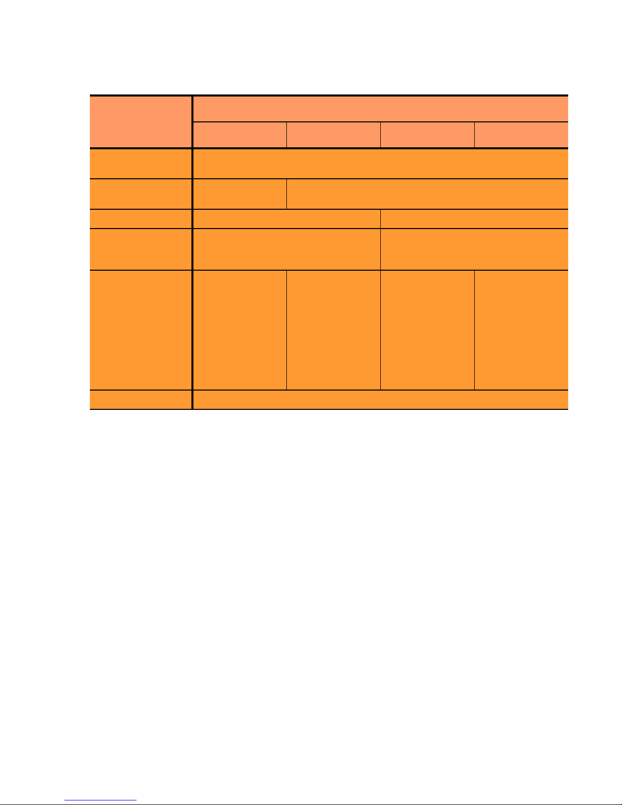
The table below summarizes the basic capabilities of the cluster types supported by Equalizer.
Cluster Type
Introducing Equalizer
Feature
Load balancing
policies
Server failure
detection (probes)
Persistence Based on IP Using Cookies
Server selection by
request content
(i.e., Match Rules)
Load balanced
protocols
NAT and spoofing Yes
a. Note that some LDAP/LDAPS implementations are UDP-based.
L4 UDP L4 TCP L7 HTTP L7 HTTPS
round robin, static weight, adaptive, fastest response,
least connections, server agent, custom
ICMP, TCP, Server
Agent
No; load is balanced according to
current load balancing policy.
Ideal for
stateless UDP-
based protocols,
such as DNS and
RADIUS; WAP
gateways; NFS
server clusters
that provide a
single-system
image.
Ideal for stateful
TCP-based
protocols, such
as HTTP, HTTPS,
SMTP, FTP,
LDAP/LDAPS
and others.
ICMP, TCP, ACV, Server Agent
Yes; load is balanced according to
decisions made by examining request
content.
HTTP HTTPS
a
Regardless of cluster type, Equalizer uses intelligent load balancing algorithms to determine the best server to
receive a request. These algorithms take into account the configuration options set for the cluster and servers, realtime server status information, and information from the request itself. For Layer 7 clusters, user-defined match
rules can also be used to determine the route a packet should take.
Load Balancing Configuration
When you configure a virtual cluster, you can select one of the following load-balancing algorithms to control how
Equalizer balances the load across your servers:
connections
, server agent, or custom.
round robin, static weight, adaptive, fastest response, least
When you configure the servers in a virtual cluster, you assign an initial weight between 0 and 200 for each server.
When you select one of the adaptive load-balancing algorithms (i.e., any algorithm other than round robin),
Equalizer uses the servers’ initial weights as a starting point to determine the percentage of requests to route to each
server. Each server handles a percentage of the total load based on its fraction of the total weights in the server
cluster. Equalizer dynamically adjusts server weights according to real-time conditions to ensure that Equalizer
routes requests to the server that is best able to respond. A server with a weight of zero (0) is considered down or
unavailable, and Equalizer does not route requests to servers in this state.
Real-Time Server Status Information
Equalizer gathers real-time information about a server’s status using ICMP Probes, TCP Probes, Active Content
Verification (ACV), and Server Agents. ICMP and TCP Probes are the default probing methods.
Equalizer Installation and Administration Guide 21

Chapter 1: Equalizer Overview
ICMP Probes uses the Internet Control Message Protocol to send an "Echo request" to the server, and then wait for
the server to respond with an ICMP "Echo reply" message (like the Unix ping command). ICMP is a Layer 3
protocol. ICMP probes can be disabled via a global flag.
TCP Probes establish (and tear down) a TCP connection between Equalizer and the server, in a typical Layer 4
exchange of TCP SYN, ACK, and FIN packets. If the connection cannot be completed, Equalizer considers the
server down and stops routing requests to it. TCP probes cannot be disabled.
Equalizer’s Active Content Verification (ACV) provides an optional method for checking the validity of a server’s
response using Layer 7 network services that support a text-based request/response protocol, such as HTTP. When
you enable ACV for a cluster, Equalizer requests data from each server in the cluster (using an ACV Probe string)
and verifies the returned data (against an ACV Response string). If Equalizer receives no response or the response
string is not in the response, the verification fails and Equalizer stops routing new requests to that server. (Note that
ACV is not supported for Layer 4 UDP clusters.) For more information, see “Using Active Content Verification
(ACV)” on page 134.
Server Agent Probes are an optional feature that enable Equalizer to communicate with a user-written program (the
agent) running on the server. A server agent is written to open a server port and, when Equalizer connects to the
port, the server agent responds with an indication of the current server load and performance. This enables Equalizer
to adjust the dynamic weights of the server according to detailed performance measurements performed by the
agent, based on any metrics available on the server. If the server is overloaded and you have enabled server agent
load balancing, Equalizer reduces the server’s dynamic weight so that the server receives fewer requests. The
interface between Equalizer and server agents is simple and well-defined. Agents can be written in any language
supported on the server (e.g., perl, C, shell script, javascript, etc.). For more information see “Server Agent Probes”
on page 255.
For those who have one or more VMware ESX Servers, Equalizer VLB can be configured to use VMware’s status
reporting to determine server status, and can also be configured to automatically manage VMware servers based on
status information obtained from VMware. For more information, see Appendix F, ”Equalizer VLB”.
Network Address Translation and Spoofing
The servers load balanced by Equalizer provide applications or services on specific IP addresses and ports, and are
organized into virtual clusters, each with its own IP address. Clients send requests to the cluster IP addresses on
Equalizer (instead of sending them to the IP addresses of the servers).
Central to the operation of any load balancer is the Network Address Translation (NAT) subsystem. On Equalizer,
NAT is used in the following ways:
1. When Equalizer receives a client packet, it always translates the destination IP (the cluster IP) to the IP address
of one of the servers in the cluster. The server IP used is determined by the cluster’s load balancing settings.
2. Depending on the setting of the cluster
When the
spoof option is enabled, then SNAT is disabled: the NAT subsystem leaves the client IP address as
the source IP address in the packet it forwards to the server. For this reason, the servers in a cluster with
enabled are usually configured to use Equalizer’s IP as their default gateway, to ensure that all responses go
through Equalizer (otherwise, the server would attempt to respond directly to the client IP).
When the
spoof option is disabled, then SNAT is enabled. Equalizer translates the source IP (the client IP) to
one of Equalizer’s IP addresses before forwarding packets to a server. The servers will send responses back to
Equalizer’s IP (so it is usually not necessary to set Equalizer as the default gateway on the servers when
is disabled).
spoof option, Equalizer may also perform Source NAT, or SNAT.
spoof
spoof
Match rules can be used to selectively apply the
selective SNAT. See the section “Changing the Spoof (SNAT) Setting Using Match Rules” on page 231.
3. When a server sends a response to a client request through Equalizer, the NAT subsystem always translates the
source IP in the response packets (that is, the server IP) to the cluster IP to which the client originally sent the
22 Equalizer Installation and Administration Guide
spoof option to client requests. This is sometimes called

Introducing Equalizer
request. This is necessary since the client sent its original request to the cluster IP and will not recognize the
server’s IP address as a response to its request -- instead, it will drop the packet.
4. NAT can also be enabled for packets that originate on the servers behind Equalizer and are destined for subnets
other than the subnet on which the servers reside -- on Equalizer, this is called outbound NAT. This is usually
required in dual network mode when reserved IP addresses (e.g., 10.x.x.x, 192.168.x.x) are being used on the
internal interface, so that the recipients do not see reserved IP addresses in packets originating from the servers.
When the global
outbound NAT option is enabled, Equalizer translates the source IP in packets from the servers
that are not part of a client connection to the Equalizer’s Default VLAN IP address (the external interface IP
address on the E250GX and legacy ‘si’ systems), or to the address specified in the server’s
Enabling
outbound NAT, as a result, has a performance cost since Equalizer is examining every outbound
Outbound NAT tab.
packet.
Note – When Equalizer is in single network mode, outbound NAT should be disabled. Since Equalizer
resides on a single subnet, outbound NAT is not needed, and may cause unexpected behavior. See “Adding
Equalizer to Your Network” on page 29 for a description of Equalizer’s network modes.
Note that when Equalizer receives a packet that is not destined for a virtual cluster IP address, a failover IP address,
a client IP address on an open connection, or one of its own IP addresses, Equalizer passes the packet through to the
destination network unaltered.
For more information:
• about setting NAT and spoofing options, see “Working with Virtual Clusters” on page 112.
• about using reserved, non-routing IP addresses with Equalizer, see Appendix C, ”Using Reserved IP
Addresses” on page 271.
Maintaining Persistent Sessions and Connections
The persistence of session data is important when a client and server need to refer to data previously generated
again and again as they interact over more than one transaction, possibly more than one connection. Whenever a
client places an item in a shopping cart, for example, session data (the item in the cart, customer information, etc.) is
created that potentially needs to persist across many individual TCP connections before the data is no longer needed
and the session is complete.
It’s important to note that session persistence is managed by the server application, not Equalizer. Equalizer provides
server persistence so that a persistent connection between a particular client and a particular server can be
maintained; this supports a client-server session where session data is being maintained on the server for the life of
the connection. In other words, whether you need to enable persistence on Equalizer depends on the application you
are load balancing.
Equalizers have no knowledge of the fact that the user has placed something in a shopping cart, logged into a web
application, requested a file from shared storage, or made a "post" in a front end presentation server that has been
written to a database. Basically, a "state" has been created in the load balanced application of which Equalizer is not
aware. What Equalizer does know is that a specific client has been load balanced to a specific server in one of its
virtual clusters. With this knowledge, Equalizer can track that information and send that client back to the same
server they were connected the first time.
Equalizer provides server or connection persistence using cookies in Layer 7 HTTP and HTTPS clusters, and using
the client IP address in Layer 4 TCP and UDP clusters. The following sections explain connection persistence
provided by Equalizer, and its relationship to session persistence.
Cookie-Based Persistence (Layer 7)
Equalizer can use cookie-based persistent connections for Layer 7 HTTP and HTTPS clusters. In cookie-based
persistence, Equalizer "stuffs" a cookie into the server's response header on its way back to the client. This cookie
Equalizer Installation and Administration Guide 23

Chapter 1: Equalizer Overview
uniquely identifies the server to which the client was just connected. The client includes (sends) the cookie in
subsequent requests to the Equalizer. Equalizer uses the information in the cookie to route the requests back to the
same server.
Equalizer can direct requests from a particular client to the same server, even if the connection is to a different
virtual cluster. For example, if a user switches from an HTTP cluster to an HTTPS cluster, the persistent cookie will
still be valid if the HTTPS cluster contains a server with the same IP address.
If the server with which a client has a persistent session is unavailable, Equalizer automatically selects a different
server. Then, the client must establish a new session; Equalizer stuffs a new cookie in the next response.
IP-Address Based Persistence (Layer 4)
For Layer 4 TCP and UDP clusters, Equalizer supports IPaddress based persistent connections. With the sticky
connection feature enabled, Equalizer identifies clients by their IP addresses when they connect to a cluster.
Equalizer then routes requests received from a particular client during a specified period of time to the same server
in the cluster.
A sticky timer measures the amount of time that has passed since there was a connection from a particular IP address
to a specific cluster. The sticky time period begins to expire as soon as there are no longer any active connections
between the client and the selected cluster. Equalizer resets the timer whenever a new connection occurs. If the client
does not establish any new connections to the same cluster, the timer continues to run until the sticky time period
expires. At expiration, Equalizer handles any new connection from that client like any other incoming connection
and routes it to an available server based on the current load balancing policy.
To correctly handle sticky connections from ISPs that use multiple proxy servers to direct user connections,
Equalizer supports sticky network aggregation, which uses only the network portion of a client's IP address to
maintain a persistent connection. Sticky network aggregation directs the user to the same server no matter which
proxy he or she connects through.
You can also configure Equalizer to ensure that it directs requests from a particular client to the same server even if
the incoming connection is to a different virtual cluster. When you enable intercluster stickiness for a cluster,
Equalizer checks the cluster for a sticky record as it receives each connection request, just like it does for ordinary
sticky connections. If Equalizer does not find a sticky record, Equalizer proceeds to check all of the other clusters
that have the same IP address. If Equalizer still does not find a sticky record, it connects the user based on the
current load balancing policy.
Is Connection Persistence Always Needed With Session Persistence?
Session persistence is a function of the application and the state created when a user logs into a web site. If the
session persistence is maintained in the front end server, then Equalizer cookie persistence should be enabled. The
client must maintain the connection to the same front end server in order for the login to remain valid. For example,
Windows Terminal Services maintains a session directory "database" when a user logs into a session. If that state or
database is in the front end server, or even in a back end server that only associates the client connection to that front
end server, then the client must "persist" to the front end server to which it is originally connected.
In other configurations, the session "state" is kept in shared storage in a backend server or database that is accessible
to all the front end servers. If this is the case, then connection persistence may not be needed; if the user is balanced
among servers, then the session can still be maintained across the front end server group via access to the shared
storage.
It’s therefore important to understand how the load balanced application provides session persistence when
managing persistent connections on Equalizer.
Layer 7 Load Balancing and Server Selection
Equalizer’s support for Layer 7 content-sensitive load balancing enables administrators to define rules for routing
HTTP and HTTPS requests, depending on the content of the request. Layer 7 load balancing routes requests based
24 Equalizer Installation and Administration Guide
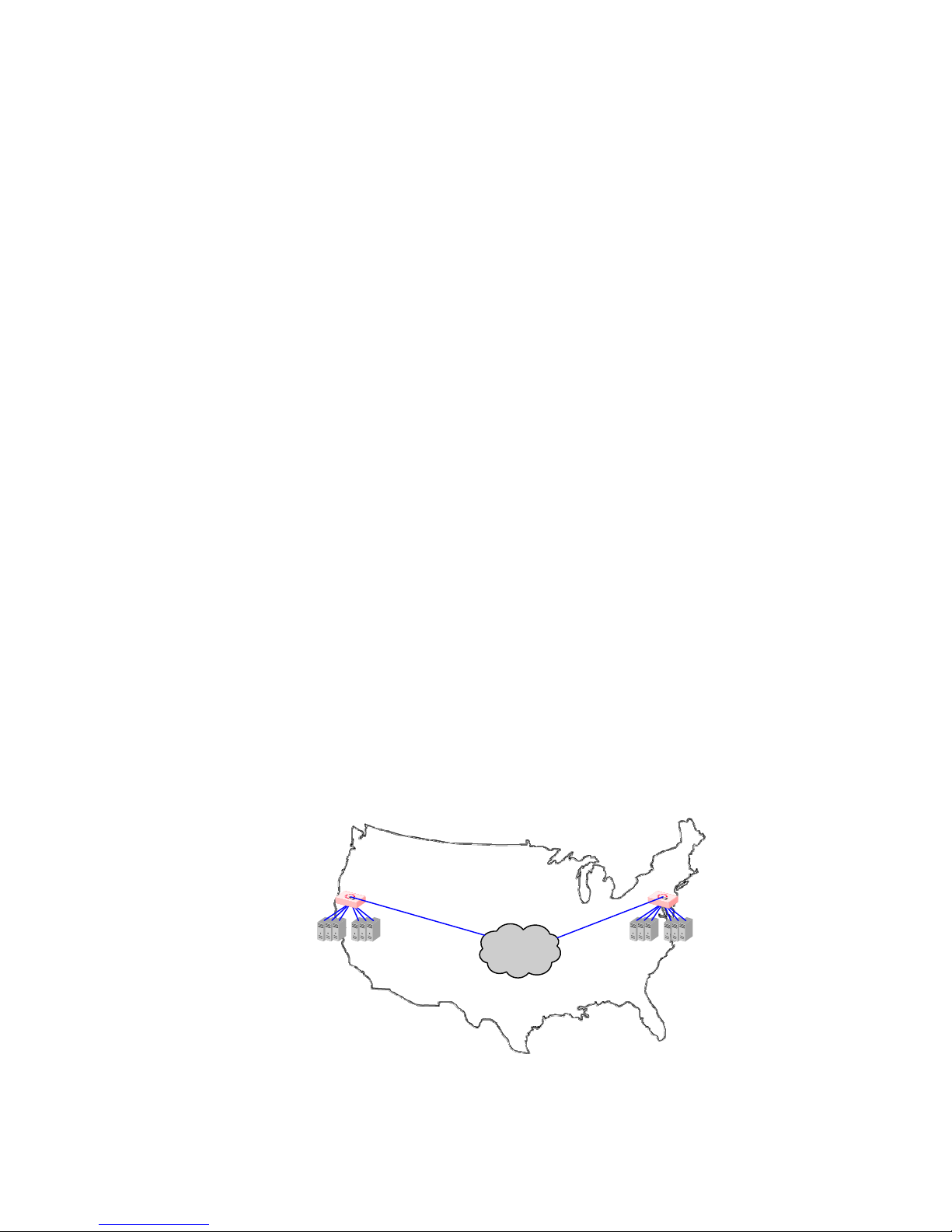
Introducing Equalizer
Internet
Envoy
Site A
Envoy
Site B
on information from the application layer. This provides access to the actual data payloads of the TCP/UDP packets
exchanged between a client and server. For example, by examining the payloads, a program can base load-balancing
decisions for HTTP requests on information in client request headers and methods, server response headers, and
page data.
Equalizer’s Layer 7 load balancing allows administrators to define rules in the administration interface for routing
HTTP and HTTPS requests according to the request content. These rules are called match rules. A match rule might,
for example, route requests based on whether the request is for a text file or a graphics file:
•
load balance all requests for text files (html, etc.) across servers A and B
• load balance all requests for graphics files across servers C, D, and E
• load balance all other requests across all of the servers
Match Rules are constructed using match functions that make decisions based on the following:
• HTTP protocol version; for HTTPS connections, the SSL protocol level the client uses to connect.
• Client IP address
• Request method (GET, POST, etc.)
• All elements of the request URI (host name, path, filename, query, etc.)
• Pattern matches against request headers
Match functions can be combined using logical constructs (AND, OR, NOT, etc.) to create extremely flexible cluster
configurations. Please see “Using Match Rules” on page 207 for an overview of Match Rules, a complete list of
match functions, and usage examples.
Geographic Load Balancing
The optional Envoy add-on supports , which enables requests to be automatically distributed across Equalizer sites
in different physical locations. An Equalizer site is a cluster of servers under a single Equalizer’s control. A is a
collection of sites that provide a common service, such as Web sites. The various sites in a geographic cluster can be
hundreds or even thousands of miles apart. For example, a geographic cluster might contain two sites, one in the
eastern U.S. and one on the U.S.’s west coast (Figure 1).
Geographic load balancing can dramatically improve reliability by ensuring that your service remains available even
if a site-wide failure occurs. Equalizer can also improve performance by routing requests to the location with the
least network latency.
Figure 1 Geographic cluster with two sites
Equalizer Installation and Administration Guide 25
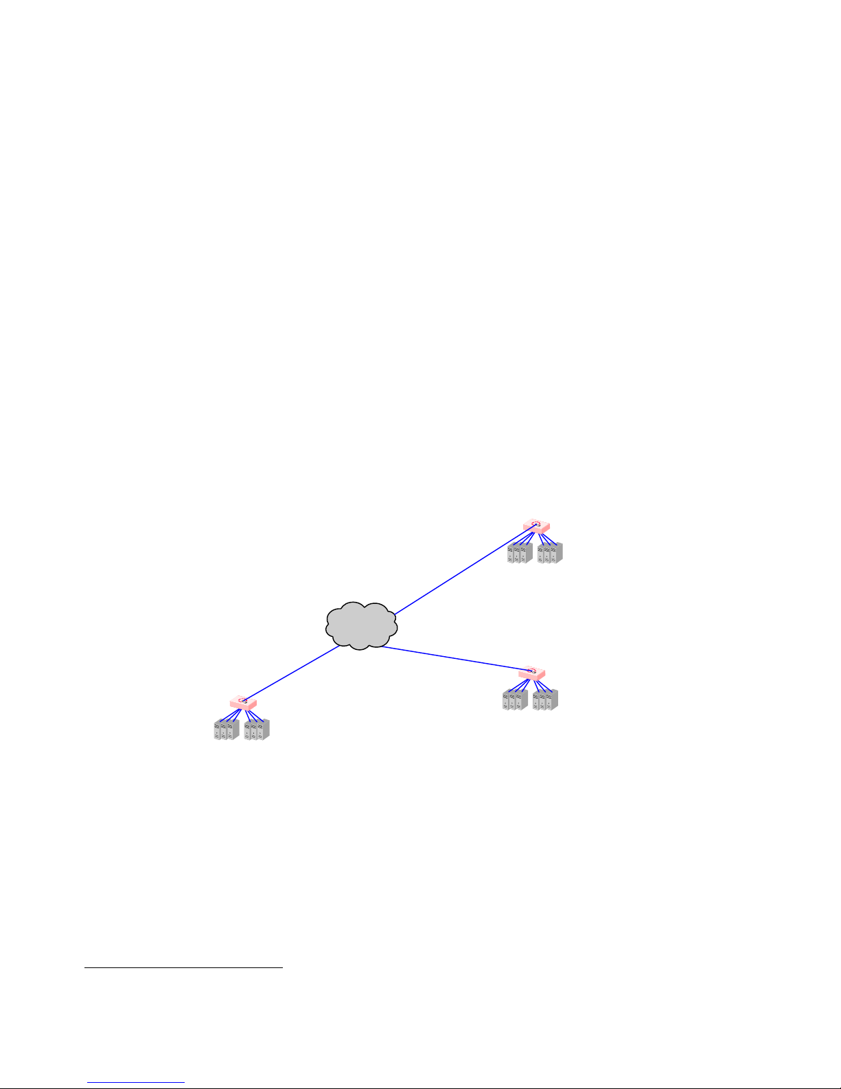
Chapter 1: Equalizer Overview
Geographic Load Balancing Routing
Envoy routes each incoming request to the site best able to handle it. If a site is unavailable or overloaded, Envoy
routes requests to the other sites in the geographic cluster. When you enable geographic load balancing, Envoy
directs incoming client requests to one of the sites in the geographic cluster based on the following criteria:
• Availability: If a site is unavailable due to network outage, server failure, or any other reason, Equalizer
stops directing requests to that site.
• Performance: Envoy tracks the load and performance at each site and uses this information to determine
the site that can process the request most efficiently.
• Distance: Envoy notes the site that is closest to the client (in network terms) and offers the least network
latency.
Distributing the Geographic Load
Envoy uses the Domain Name System (DNS) protocol1 to perform its geographic load distribution. DNS translates
fully-qualified domain names such as
Internet. For Envoy, the authoritative name server for the domain is configured to query the Equalizers in the
geographic cluster to resolve the domain name. When Envoy receives a resolution request, it uses the load-balancing
algorithms configured for the geographic cluster to determine the site that is best able to process the request and then
returns the address of the selected site.
www.coyotepoint.com into the IP addresses that identify hosts on the
For example, the geographic cluster
www.coyotepoint.com might have three sites (see Figure 2): one on the east
coast of the U.S., one on the west coast of the U.S., and one in Europe. The servers at each site are connected to an
Equalizer with the Envoy add-on installed.
Envoy Site C
(Europe)
Internet
Envoy Site A
(East Coast USA)
Envoy Site B
(West Coast USA)
Figure 2 Three-site geographic cluster configuration
When a client in California attempts to connect to coyotepoint.com:
1. For more information about DNS, see Paul Albitz and Cricket Liu, DNS and BIND, 3rd ed. (O'Reilly & Associates, 1998).
26 Equalizer Installation and Administration Guide

1. The client queries its local DNS server to resolve the domain name (see Figure 3).
Envoy Site B
(West Coast USA)
Envoy Site A
(East Coast USA)
Internet
Envoy Site C
(Europe)
Client
(California, USA)
Client’s
Local DNS
Authoritative
DNS
for
coyotepoint.com
Envoy Site B
(West Coast USA)
Envoy Site A
(East Coast USA)
Internet
Envoy Site C
(Europe)
Client
(California, USA)
Client’s
Local DNS
Authoritative
DNS
for
coyotepoint.com
Introducing Equalizer
Figure 3 Client queries its local DNS for coyotepoint.com
2. The local DNS server queries the authoritative name server for coyotepoint.com (see Figure 4).
Figure 4 Client’s local DNS queries the authoritative name server for coyotepoint.com
Equalizer Installation and Administration Guide 27
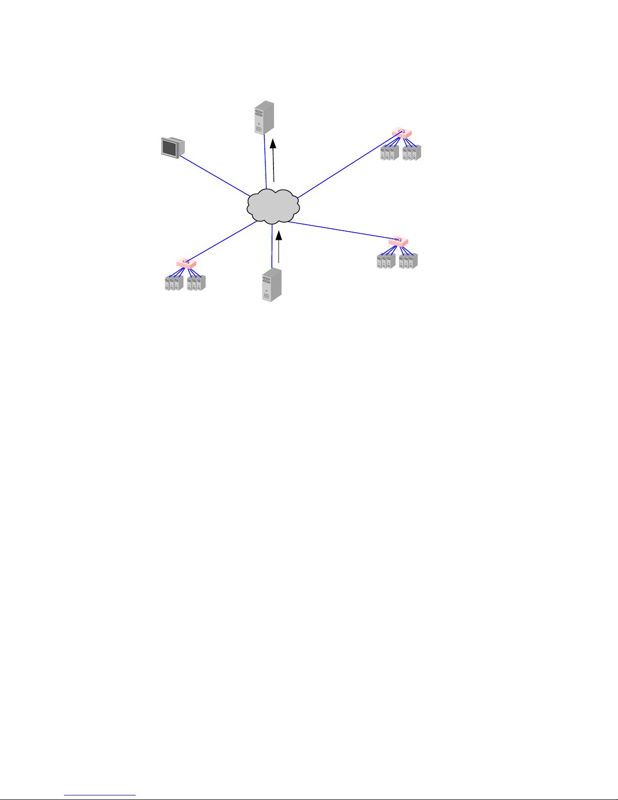
Chapter 1: Equalizer Overview
Envoy Site B
(West Coast USA)
Envoy Site A
(East Coast USA)
Internet
Envoy Site C
(Europe)
Client
(California, USA)
Client’s
Local DNS
Authoritative
DNS
for
coyotepoint.com
3. The authoritative name server provides a list of Envoy-enabled Equalizer sites and returns this list to the client’s
local DNS server (see Figure 5).
Figure 5 The authoritative name server for coyotepoint.com returns a list of delegates
4. The client’s DNS server sends a request for the IP address of coyotepoint.com to each Envoy site in the list
until one of them responds.
5. The Envoy site contacted returns the IP Address of the virtual cluster best able to handle the client’s request.
6. Finally, the client’s local DNS server returns the virtual cluster IP to the client, which then sends the request to
(For an overview of how Envoy chooses the virtual cluster IP to return to the client’s DNS, see “Administering
GeoClusters” on page 237.)
the virtual cluster.
28 Equalizer Installation and Administration Guide
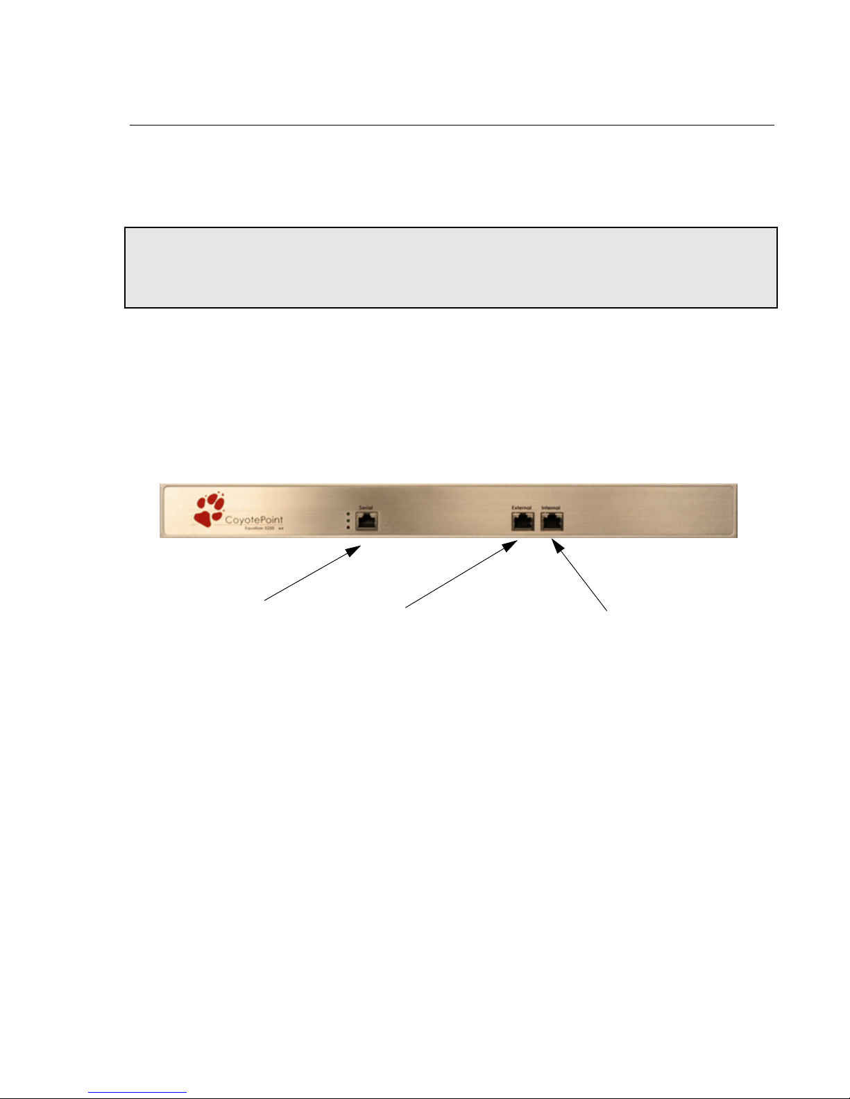
Adding Equalizer to Your Network
Serial Port
External Interface Port
Internal Interface Port
Adding Equalizer to Your Network
Equalizer is a versatile traffic management and application acceleration solution that is easily configured for your
network. Equalizer models E350GX and above have 12 or more front panel network switch ports, are Virtual Local
Network (VLAN) capable, and can be configured for tagged and untagged VLANs. Equalizer model E250GX has
two front panel ports configured into two port based VLANs.
Note – VLAN management capabilities were introduced in Version 8.6 of the Equalizer O/S software on Equalizer
GX hardware. If you are running Version 8.6 or later on pre-GX Equalizer hardware (such as the ‘si-R’ hardware),
the front-panel switches are managed as they were in Version 8.5 of the Equalizer software. Please refer to the
Version 8.5 Installation and Administration Guide at docs.coyotepoint.com.
Equalizer E250GX Network Configuration
Equalizer model E250GX has two front-panel network interface ports configured into two untagged (or port-based)
Virtual Local Networks (VLANs): the External Network VLAN and the Internal Network VLAN. Initial network
configuration of Equalizer is performed over the serial port, where you assign an IP address to one or both of the
network interface ports. The figure below shows the port configuration of an E250GX model Equalizer.
Figure 6 Equalizer E250GX default port configuration
The E250GX can be deployed in either a single network or a dual network configuration:
•In a single network configuration, all cluster IPs and server IPs are on the same subnet, and are connected
to Equalizer using the Internal Interface Port; the External Interface Port is unused.
•In a dual network configuration, all cluster IPs are on one subnet connected to Equalizer using the External
Interface Port, while servers are on another subnet connected to Equalizer’s Internal Interface Port.
Equalizer Installation and Administration Guide 29
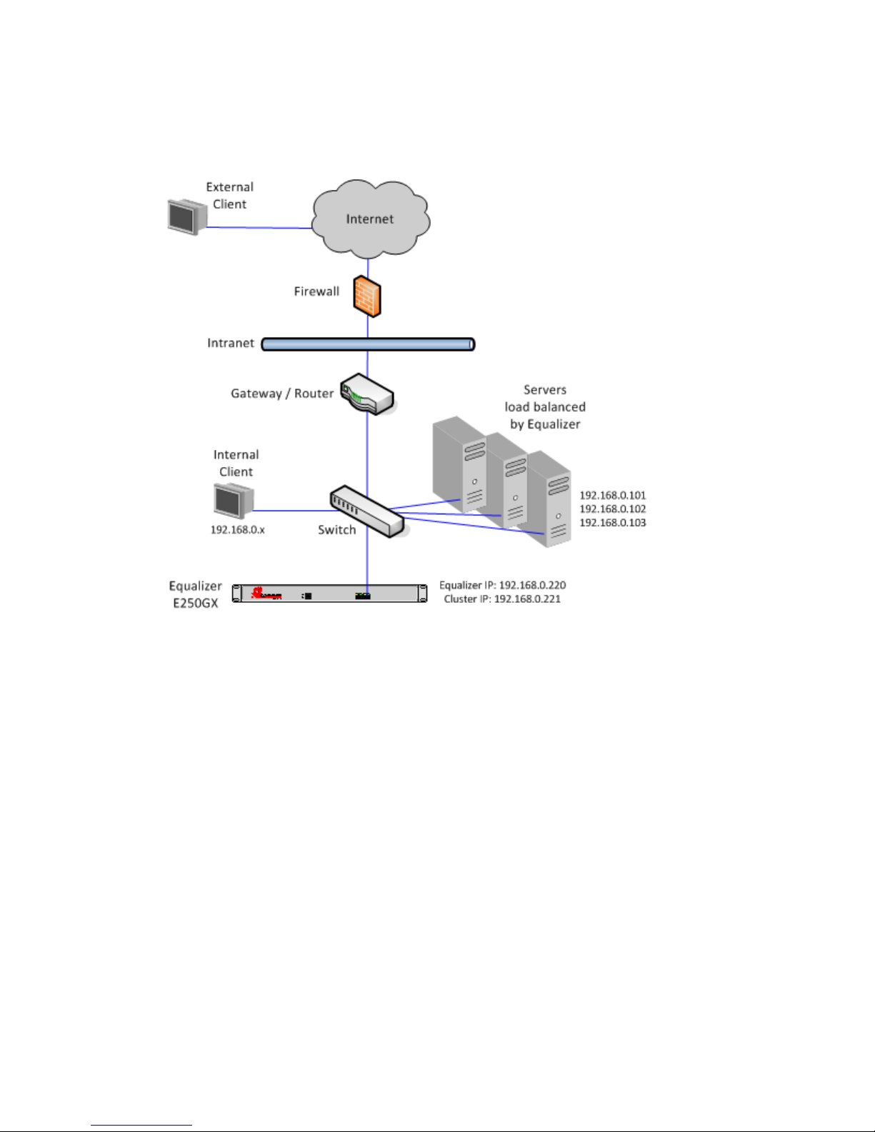
Chapter 1: Equalizer Overview
Using Equalizer E250GX in a Single Network Environment
In single network mode, the client systems, servers, Intranet and/or Internet must all connect to Equalizer through
the Internal Interface Port. Figure 7 shows an example.
Figure 7 Example single network configuration for Equalizer E250GX
Single network mode is often the simplest way to fit Equalizer into an existing network with minimal changes to the
current network infrastructure. Certain protocols and applications that use dynamic port mapping or multiple TCP/
UDP ports may also work best in a single network environment.
As you can see in the example above, Equalizer’s internal IP, cluster IP, and all server IPs are located on the
192.168.0.x network, and communicate through the same switch. The switch, in turn, is connected to a router which
is this subnet’s gateway to other subnets on the Intranet and Internet networks. The gateway or router that conects
Equalizer’s subnet to the Intranet and Internet is assumed to perform all necessary NAT for external clients, so they
can access Equalizer’s cluster IPs.
Internal clients can access the cluster IPs directly, and so may require selective SNAT on Equalizer or special routing
on the servers to ensure that all server responses go through Equalizer.
30 Equalizer Installation and Administration Guide
 Loading...