

Coyote DataCom DR915 Users Manual

DR-915 Data Radio Module
INTEGRATOR’S GUIDE
Coyote DataCom, Inc. 12721 Benson, Overland Park, KS 66213 • Tel. 913-685-8350 • Fax 913-685-0732
www.coyotedatacom.com • sales@coyotedatacom.com

DR-915 OEM DATA RADIO MODULE
___________________________________________________________________________________________
TABLE OF CONTENTS
General Information..............................................................................3
RF Exposure Statement.........................................................................3
Configuration........................................................................................6
Specifications......................................................................................14
DR-915 Mechanical Overview...............................................................15
Pin Definitions.....................................................................................16
Approved Antennas.............................................................................18
In-System Configuration......................................................................19
FCC Compliance Warning and Class B Statement ..................................24
Revision A INTEGRATOR’S
GUIDE
2

DR-915 OEM DATA RADIO MODULE
___________________________________________________________________________________________
DR-915 Data Radio
General Information
This DR-915 is a frequency hopping spread spectrum data transceiver operating in the
902-928 MHz ISM band. The unit is designed to operate under Part 15.247 of the FCC
rules and regulations and is designed as an OEM module for integration into other
products or field devices. When installed using an approved antenna, the user need
only ensure that the radio’s FCC label or a copy of the FCC label is clearly visible on the
outside of the integrated product.
Caution: If this radio is integrated into another product, the user is responsible for
complying with the external labeling requirements as directed in the FCC Rules and
Regulations part 15.19. To avoid obtaining an FCC certification, the user may only use
antennas that have been tested and approved for use with this radio.
The unit operates on 25 discrete frequencies within the ISM band, each frequency
about 800kHz apart. Using a frequency agile phase-locked loop synthesizer, the radio is
able to scan all 25 channels and quickly acquire synchronization with a transmitting
radio.
The radio is connected to a host device using a 10-pin SIP header. This connection
provides the radio with the required DC power source, allows it to be programmed and
configured and provides all I/O lines for both an asynchronous serial as well as an SPI
interface.
Revision A INTEGRATOR’S
GUIDE
3

DR-915 OEM DATA RADIO MODULE
___________________________________________________________________________________________
DR-915 DATA RADIO
REGULATORY
FCC RF Exposure Statement
This device complies with FCC radiation exposure limits as set forth for an uncontrolled
environment.
This device should be installed and operated with a minimum separation distance of 20
cm between the radiator and your body.
Revision A INTEGRATOR’S
GUIDE
4

DR-915 OEM DATA RADIO MODULE
___________________________________________________________________________________________
DR-915 DATA RADIO
CONFIGURATION
Default Settings
Serial Baud..............................................................................9600 bits/second
Port......................................................................................................... UART
RX buffer size.................................................................................. 190 bytes*
TX buffer size .................................................................................. 190 bytes*
CTS assert....................................................................................... 180 bytes*
CTS de-assert.................................................................................. 150 bytes*
TX assert.................................................................................180 bytes*/5 mS
Channel..........................................................................................................1
Source Address...............................................................................................1
Destination Group...........................................................................................1
Destination Address ........................................................................................1
Acknowledgement.....................................................................................None
Power save .................................................................................................. Off
*Factory setting; cannot be changed.
Revision A INTEGRATOR’S
GUIDE
5
DR-915 OEM DATA RADIO MODULE
___________________________________________________________________________________________
DR-915 DATA RADIO
CONFIGURATION
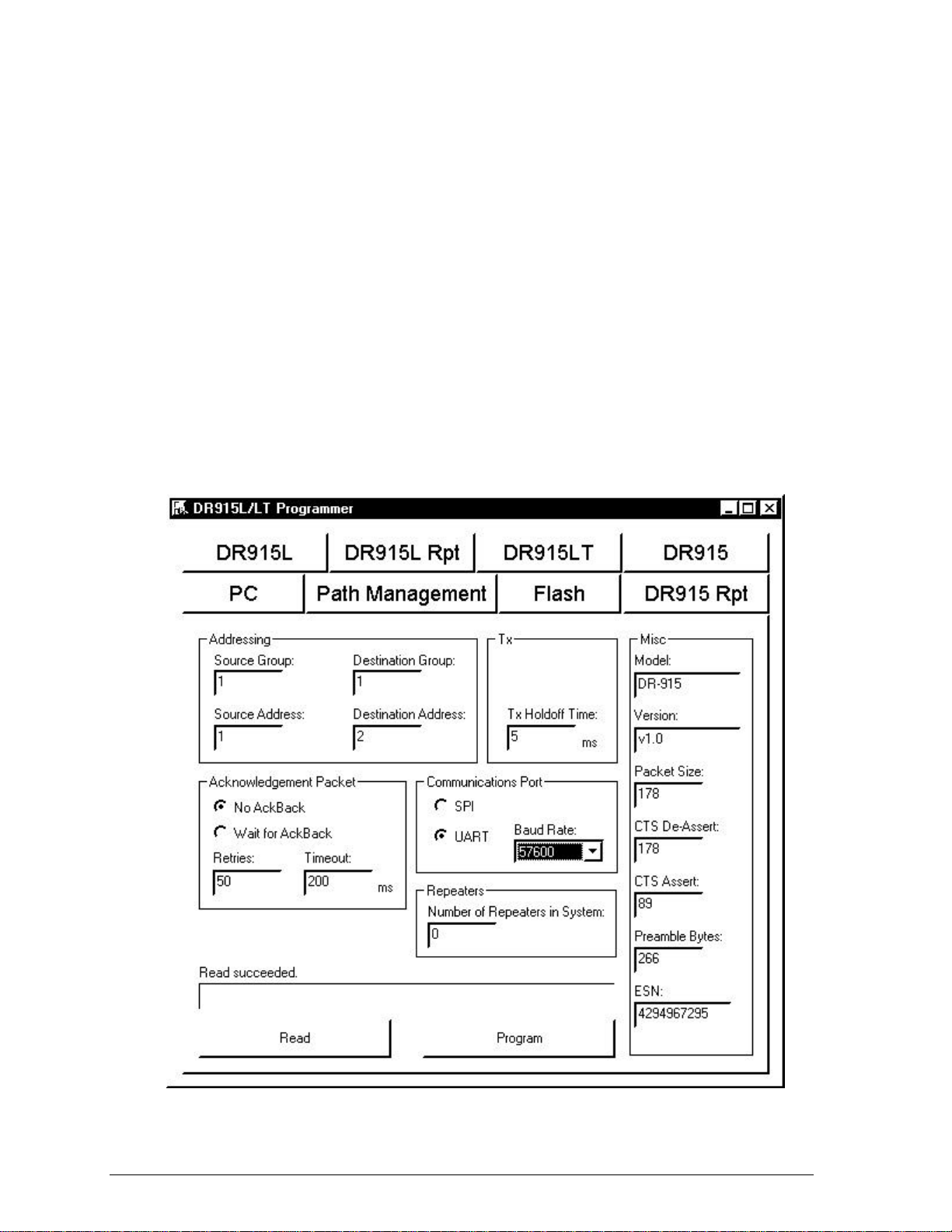
The DR-915 is supplied with an easy to use Windows98™ configuration program. The
configuration program allows the user to control the operation of their radio network.
Installing
The configuration software does not require an installation. Simply run it from the CD
labeled “DR-915 Tools” or copy it onto another drive. Start the program by locating
and double clicking on the “Programmer” icon. This will launch the configuration
program and display the screen below.
Revision A INTEGRATOR’S
GUIDE
6
DR-915 OEM DATA RADIO MODULE
___________________________________________________________________________________________
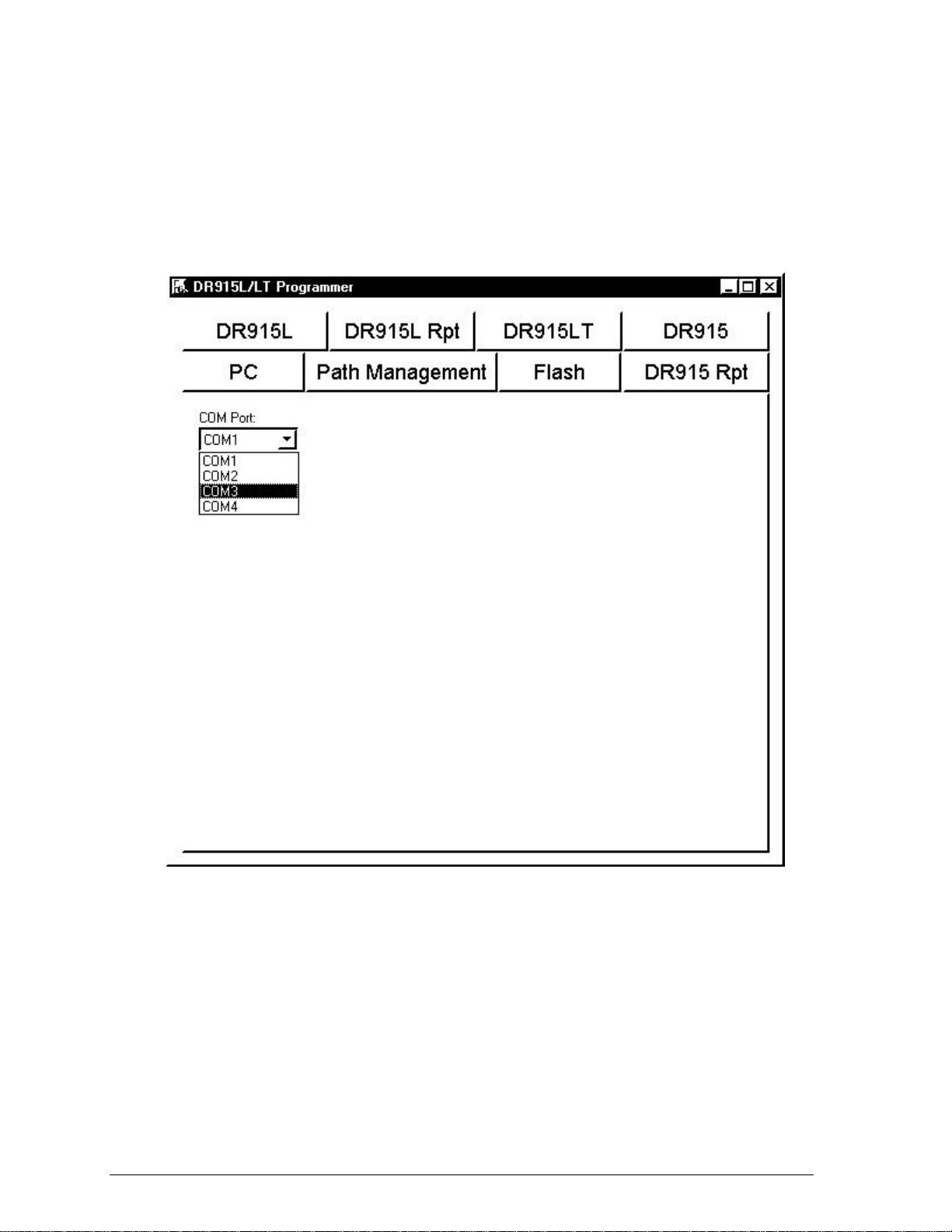
Click on the “PC Settings” tab, then select which COM port will be used to connect to
the data radio. As shown below, COM1 thru COM4 are available. This setting will be
retained the next time the configuration program is run.
Getting Started
To configure the radio, click on appropriate tab for the radio being configured. Then
select the radio Communications Port. The default setting is for asynchronous serial
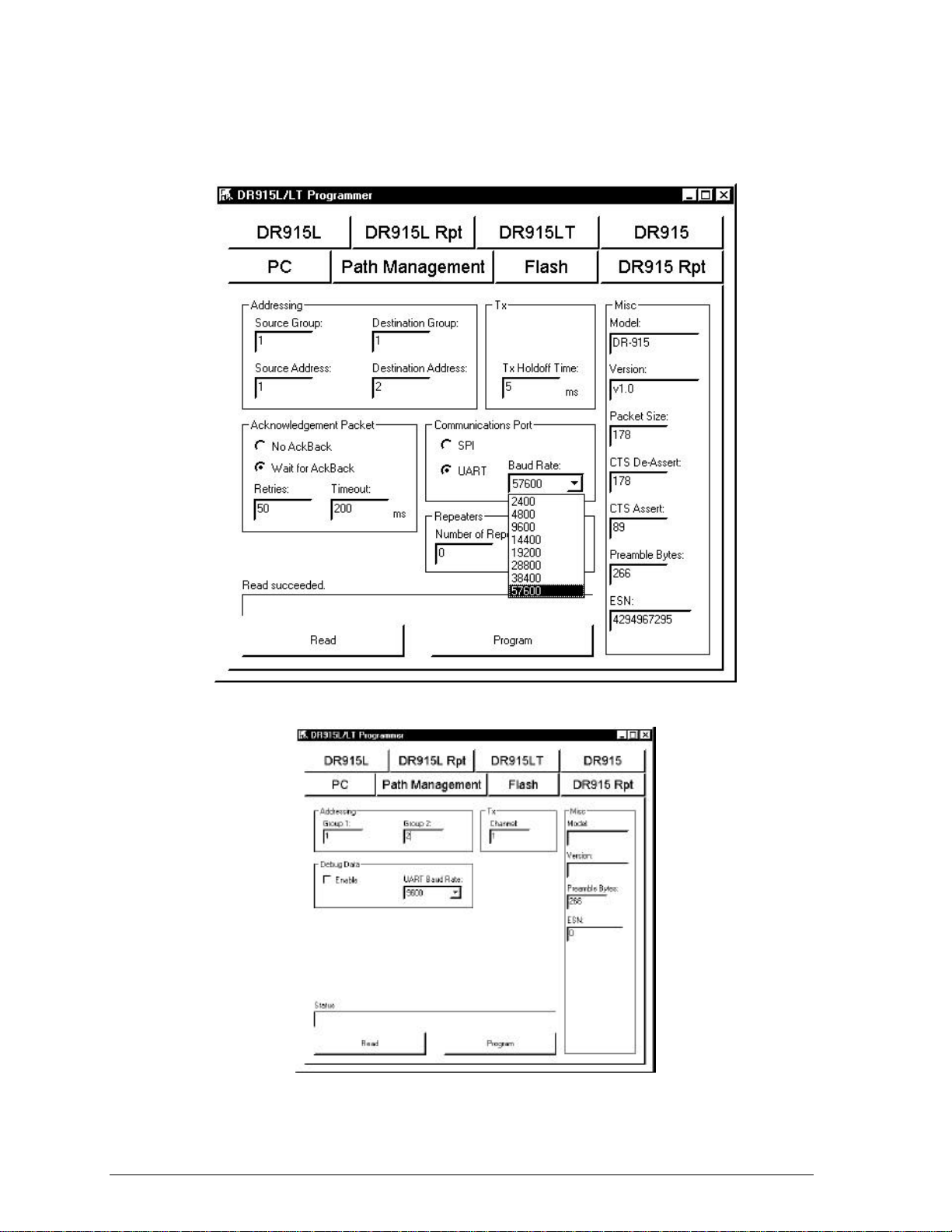
mode, UART (Universal Asynchronous Receiver/Transmitter). The default baud rate is
9600 bits per second. The interface baud rate can be set to standard values between
2400 and 57600 as shown on the following page. This mode supports 8 data bits, 1
stop bit and no parity.
Revision A INTEGRATOR’S
GUIDE
7
DR-915 OEM DATA RADIO MODULE
___________________________________________________________________________________________
DR-915 Repeater
Revision A INTEGRATOR’S
GUIDE
8
 Loading...