


CDR-9150 Data Radio Module
INTEGRATOR’S GUIDE
Coyote DataCom, Inc. 12721 Benson, Overland Park, KS 66213 • Tel. 913-685-8350 • Fax 913-685-0732
www.coyotedatacom.com • sales@coyotedatacom.com

CDR-9150 OEM DATA RADIO MODULE
2
___________________________________________________________________________________________
TABLE OF CONTENTS
General Information and Labeling Requirements.....................................3
FCC RF Exposure Statement ..................................................................4
Configuration........................................................................................6
Specifications......................................................................................14
CDR-9150 Mechanical Overview...........................................................15
Pin Definitions.....................................................................................16
Approved Antennas.............................................................................18
RS-232 Interface Board.......................................................................19
In-System Configuration......................................................................19
Hardware Timing ................................................................................23
FCC Compliance Warning and Class B Statement ..................................28
Revision B INTEGRATOR’S GUIDE

CDR-9150 OEM DATA RADIO MODULE
3
___________________________________________________________________________________________
CDR-9150 Data Radio
General Information and Labeling Requirements
This CDR-9150 is a frequency-hopping spread spectrum data transceiver operating in
the 902-928 MHz ISM band. The unit is designed to operate under Part 15.247 of the
FCC rules and regulations and is designed as an OEM module for integration into other
products or field devices. When installed using an approved antenna, the user need
only ensure that the appropriate FCC information is clearly visible on the outside of the
integrated product. This label should contain one of the following phrases to be
considered valid.
1. "Contains Transmitter Module FCC ID: PHO-CDR9150" or
2. "Contains FCC ID: PHO-CDR9150
For integration into products sold in Canada, the label should read as follows.
Contains Transmitter Module IC: 4315A-CDR9150
The term “IC:” before the certification/registration number only signifies
that the Industry Canada technical specifications were met.
Caution: If this radio is integrated into another product, the user is responsible for
complying with the external labeling requirements as directed in the FCC Rules and
Regulations Part 15.19. To avoid the need to obtain additional certification, the user
should only use antennas that have been tested and approved for use with this radio.
The unit operates on 50 discrete frequencies within the ISM band, each frequency
about 400 kHz apart. Using a frequency agile phase-locked loop synthesizer, the radio
is able to scan all 50 channels and quickly acquire synchronization with a transmitting
radio.
The radio is connected to a host device using a 10-pin SIP header. This connection
provides the radio with the required DC power source, allows it to be programmed and
configured and provides all I/O lines for an asynchronous serial interface.
Revision B INTEGRATOR’S GUIDE

CDR-9150 OEM DATA RADIO MODULE
4
___________________________________________________________________________________________
CDR-9150 DATA RADIO
REGULATORY
FCC RF Exposure Statement
This device complies with FCC radiation exposure limits as set forth for an uncontrolled
environment.
When using the antennas listed below, this device should be installed and operated with
a minimum separation distance of 20 cm between the radiator and your body.
• ¼ wave rubber whip
• ¼ wave mobile whip 0dB
• 5/8 over 5/8, 5dB center loaded mobile
• 5/8 wave, 3dB mobile whip
• Dome antenna, 0dB
• Low profile, tamper resistant, 0dB
When using the antennas listed below, this device should be installed and operated with
a minimum separation distance of 2 meters between the radiator and your body. These
antennas should not be installed indoors.
• 5dB fiberglass monopole
• 6dB 3 element Yagi
Revision B INTEGRATOR’S GUIDE

CDR-9150 OEM DATA RADIO MODULE
5
___________________________________________________________________________________________
CDR-9150 DATA RADIO
CONFIGURATION
Default Settings
Serial Baud............................................................................. 9600 bits/second
Port......................................................................................................... UART
RX buffer size..................................................................................190 bytes*
TX buffer size .................................................................................. 190 bytes*
CTS assert...........................................................................................89 bytes
CTS de-assert....................................................................................178 bytes
Packet size ........................................................................................177 bytes
Preamble bytes..................................................................................266 bytes
TX assert.................................................................................. 177 bytes/5 mS
Ack-Back™ retries.........................................................................................15
Ack-Back™ timeout............................................................................... 200 mS
Channel..........................................................................................................1
Source Address...............................................................................................1
Destination Group...........................................................................................1
Destination Address ........................................................................................1
Ack-Back™ mode.........................................................................................Off
*Factory setting; cannot be changed.
Revision B INTEGRATOR’S GUIDE
CDR-9150 OEM DATA RADIO MODULE
6
___________________________________________________________________________________________
CDR-9150 DATA RADIO
CONFIGURATION
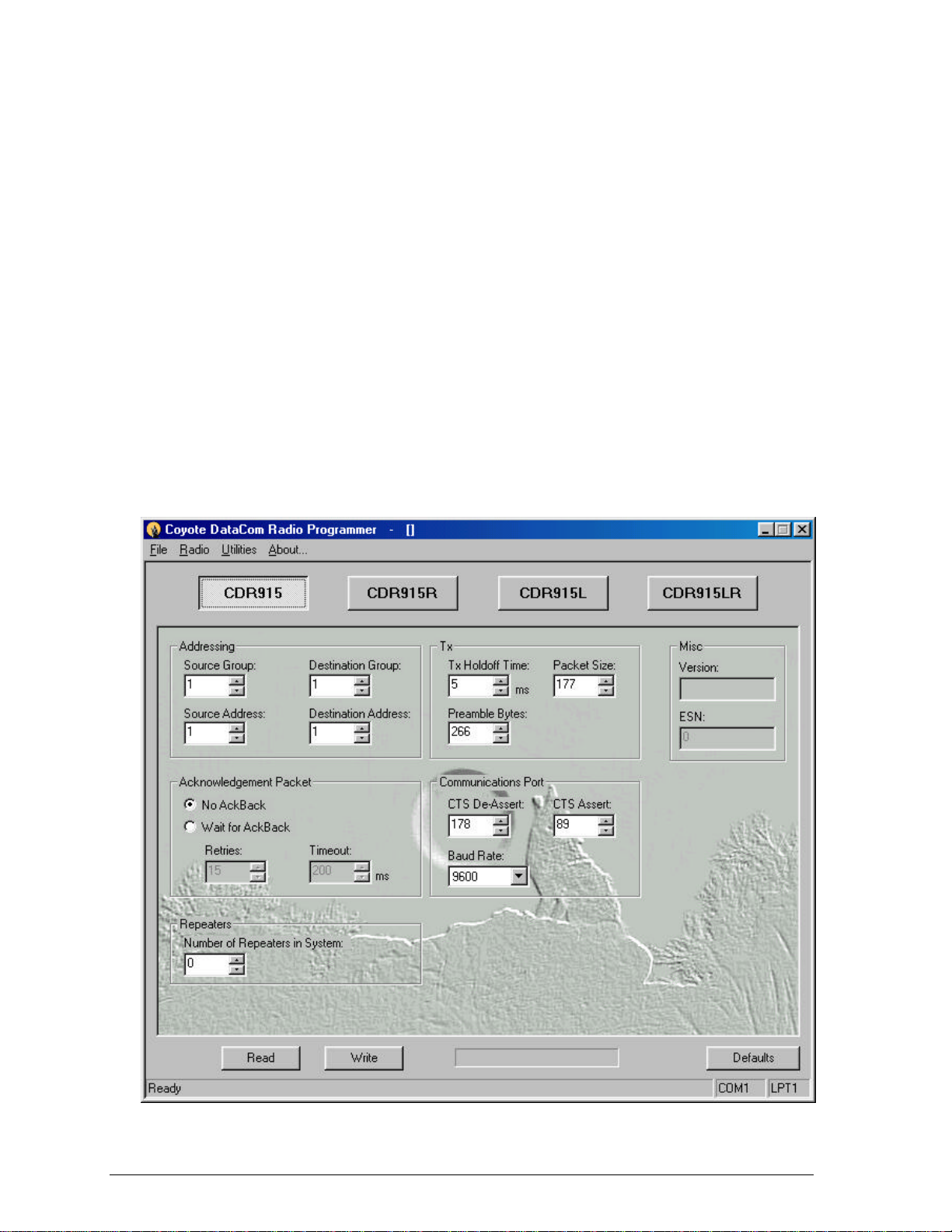
The CDR-9150 is supplied with an easy-to-use Windows98™ configuration program.
The configuration program allows the user to control the operation of their radio
network.
Installing
The configuration software does not require an installation. Simply run it from the CD
labeled “CDR-9150 Tools” or copy it onto another drive. Start the program by locating
and double-clicking on the “Programmer” icon. This will launch the configuration
program and display the screen below.
Revision B INTEGRATOR’S GUIDE
CDR-9150 OEM DATA RADIO MODULE
7
___________________________________________________________________________________________
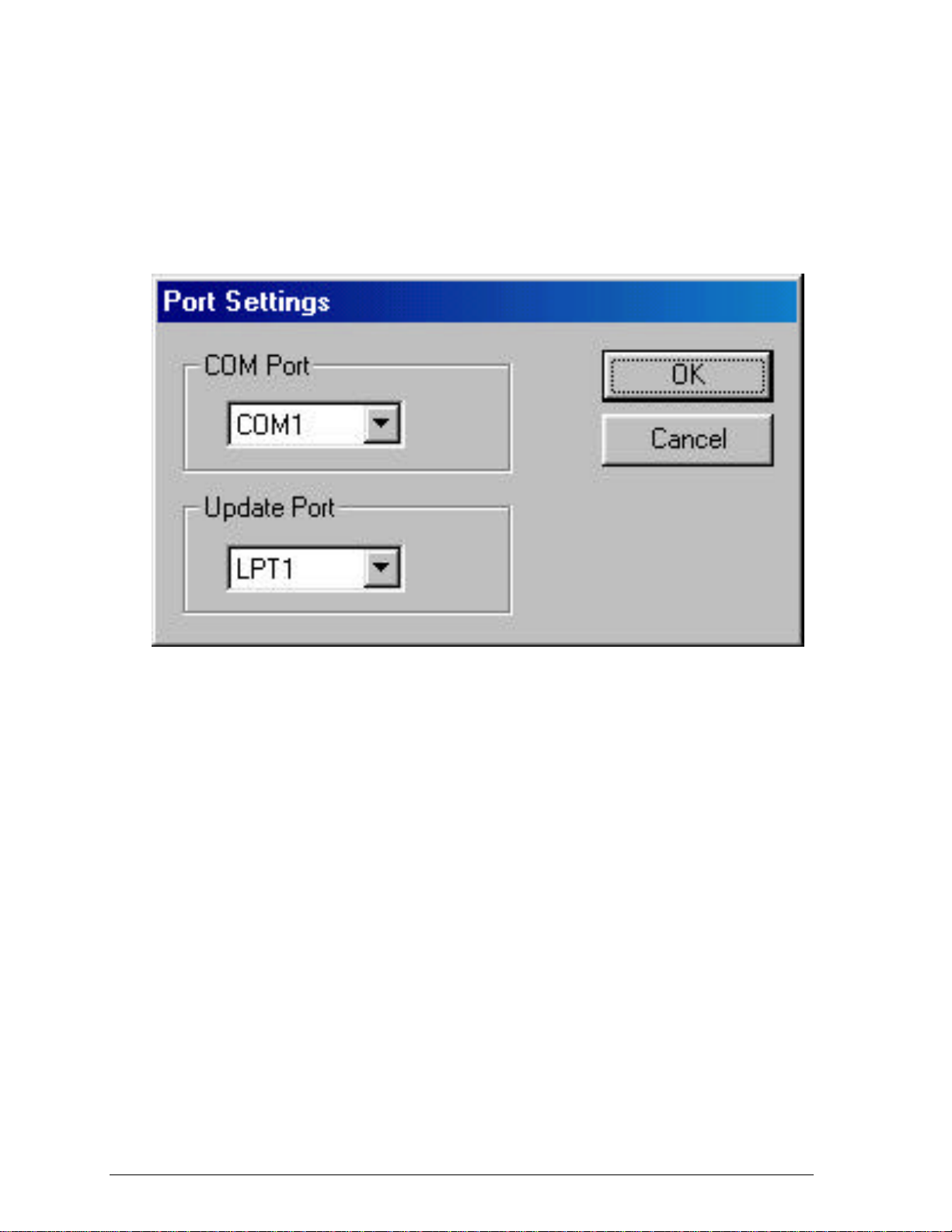
Click on the “PC Settings” tab, then select which COM port will be used to connect to
the data radio. As shown below, ports COM1 thru COM4 are available. This setting will
be retained the next time the configuration program is run.
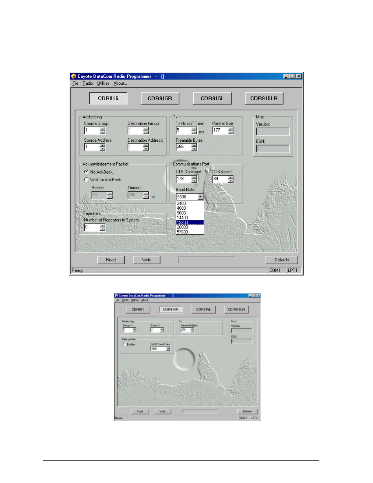
Getting Started
To configure the radio, click on the appropriate tab for the radio being configured. Then
select the radio Communications Port. The default setting is for asynchronous serial
mode, UART (Universal Asynchronous Receiver/Transmitter). The default baud rate is
9600 bits per second. The interface baud rate can be set to standard values between
2400 and 57600 as shown on the following page. This mode supports 8 data bits, 1
stop bit and no parity.
Revision B INTEGRATOR’S GUIDE
CDR-9150 OEM DATA RADIO MODULE
8
___________________________________________________________________________________________
CDR-9150 Repeater
Revision B INTEGRATOR’S GUIDE

CDR-9150 OEM DATA RADIO MODULE
9
___________________________________________________________________________________________
Addressing
The radio has been designed to be very versatile in its addressing functions. Each radio
has its own identifier consisting of a group number and address number.
The Source Group specifies which group of radios the unit being configured belongs to.
The Source Address specifies the address within that group that uniquely identifies this
radio. The radio will decode packets containing a Destination Group and Address
matching its own. With the exception of broadcast messages, all others will be ignored.
Broadcast messages are those messages where the destination address is 0 and the
group is the same as the radio receiving it, or those messages where the destination
address and group are both 0. When the destination group is set to 0, all radios in all
groups will decode the packet.
Likewise, the Destination Group specifies which group of radios the transmissions will
go to. The Destination Address specifies the individual radio within that group that will
receive the message.
TX Hold Off Time
TX Hold Off Time sets the amount of time that must elapse after the last byte to be
transmitted is received by the radio before a transmit packet will be initiated. Setting
this value higher will prevent numerous small packets from being sent when the
transmit data is not continuous. The default setting will be adequate for most
applications.
Acknowledgement (Ack-Back™)
The CDR-9150 has powerful built-in path management features designed to make OEM
integration quick and easy. Activating packet acknowledgement will virtually guarantee
all data transmitted is received. Any packet transmitted by the CDR-9150 is then
acknowledged by the receiving radio. If any packet is not acknowledged, the
transmitting radio will resend the data. While reducing throughput, this feature also
handles missed transmissions as well as performs path management, allowing full
duplex communications.
The Retries field specifies the number of attempts the radio will make in trying to
resend unacknowledged packets. The Timeout field determines how long the radio will
wait for the acknowledgement before resending. (See Hardware Timing for more
information)
Revision B INTEGRATOR’S GUIDE

CDR-9150 OEM DATA RADIO MODULE
10
___________________________________________________________________________________________
Number of Repeaters
The range of the CDR-9150 may be extended by using repeaters. Repeater modules
receive data packets on one group code and retransmit the packet on another group
code. For example, a repeater configured with group codes 3 and 4 will translate the
following packets and retransmit them as follows:
• A packet received with a destination group code of 3 will be received and
retransmitted with a destination group of 4.
• A packet received with a destination group code of 4 will be received and
retransmitted with a destination group of 3.
This method of group code translation guarantees that data is transferred through the
repeater and not directly between radios.
When the CDR-9150 is in Ack-Back™ mode and there are repeaters in the system, the
amount of time needed to receive packet acknowledgements increases. By specifying
the number of repeaters in the Configuration program, this delay is calculated and the
radio is updated correctly. Always set this field with the maximum number of
chained repeaters in the system.
Revision B INTEGRATOR’S GUIDE

CDR-9150 OEM DATA RADIO MODULE
11
___________________________________________________________________________________________
Path Management
The CDR-9150 has powerful path management tools to help ensure successful field
installations. The Path Management window has two modes, Continuous and On-Sync.
The Continuous mode allows the installer to look at competing signals on the radio’s
channel and determine if there is a potential interference problem. Running in this
mode for an extended period of time will show the installer the level of the strongest
signal seen by the radio. The solid indicator needle indicates the current signal level
being received while the dashed indicator needle shows the strongest signal received.
Clicking the Stop button will reset the dashed indicator.
Continuous Mode Signal Monitoring
Revision B INTEGRATOR’S GUIDE

CDR-9150 OEM DATA RADIO MODULE
12
___________________________________________________________________________________________
The On-Sync mode allows the installer to look only at radio transmissions for CDR-9150
radios. When packets are received, the transmission’s current and maximum signal
strength is displayed along with the packet’s source group code and address. This
allows the installer to ensure there is adequate signal strength with enough fade margin
to guarantee reliable operation. Signals in the green area are considered very reliable,
those in the yellow area are marginally reliable and signals in the red area are
considered not reliable.
The graph will display information for as many as 16 radio addresses. As new addresses
are received, they will replace the oldest ones in the graph. The last received signal is
indicated by a crosshatch in the bar. Clicking on the Stop button will reset the graph
information.
On-Sync Signal Monitoring
Revision B INTEGRATOR’S GUIDE

CDR-9150 OEM DATA RADIO MODULE
13
___________________________________________________________________________________________
Code Upgrading
The CDR-9150 has been designed for easy field upgrades. Using the RS-232 Serial
Adapter board, a DR915 Programming cable, a standard Serial Configuration cable and
a current version of the CDR-9150 Configuration program running on the user’s PC, the
radio can be re-flashed with new operating code. Special customer code can also be
loaded in this manner.
With the radio mounted on an RS232 Serial Adapter board, connect a program upgrade
cable from the programming connector, J4, on the Adapter board to the parallel port on
the PC. Connect a standard DB9 male-to-female serial cable from the Adapter board’s
DB9, J2, and to the serial port on the PC. Power the Adapter board using the supplied
12-volt wall module connected to the Adapter board’s power jack, P8.
Using the CDR-9150 Configuration program, click on the Flash tab. Select the desired
software version from the Software Version drop-down box and then press the Program
Flash button. The Configuration program will then read the setup information from the
radio, upgrade the radio code and reload the original configuration.
Flash Upgrade Tab
Revision B INTEGRATOR’S GUIDE

CDR-9150 OEM DATA RADIO MODULE
14
___________________________________________________________________________________________
CDR-9150 Data Radio
SPECIFICATIONS
Overall
Frequency ....................................................................................902-928 MHz
Frequency Control..................................................................... PLL Synthesizer
Transport ...............................................Transparent, Point-to-Point Guaranteed
Data Interface ............................................................ Asynchronous Serial, TTL
Hopping Channels.........................................................................................50
Configuration.................................Windows98™ Application using PC Serial Port
Duty Cycle.............................................................100% receive, 50% transmit
Data Interface Rate................................. 2400,4800,9600,19.2k,56k bps (N,8,1)
Temperature................................................................................ -30 to +70 °C
Range ....................................................up to 10 miles depending on conditions
Data Encoding..................................................................... Proprietary Method
Receiver Sensitivity..................................................................-101 dBm usable
Modulation ............................................................................... Direct FM (FSK)
RF Data Rate........................................................................................50 kbps
Data Flow Control...............................................................Hardware using CTS
Transmitter Output ............................................................................... 200mW
Error Detection.................................................................................16 bit CRC
Power Requirements
Input Voltage...................................................................................8 – 32 VDC
Input Current.....................................................................80 mA Receive Mode
800 mA Transmit Mode
Regulatory
United States (FCC)...........................................................CFR 15.247 Approved
Canada (IC)..........................................................................RSS-210 Approved
Mechanical
Size................................................................................................2.1” x 4.25”
Antenna Connector ....................................................................... Reverse SMA
Revision B INTEGRATOR’S GUIDE

CDR-9150 OEM DATA RADIO MODULE
15
___________________________________________________________________________________________
CDR-9150 Data Radio
RADIO HARDWARE INTERFACE
CDR-9150 Mechanical Overview
TTO Be Added
Revision B INTEGRATOR’S GUIDE

CDR-9150 OEM DATA RADIO MODULE
16
___________________________________________________________________________________________
CDR-9150 Data Radio
RADIO HARDWARE INTERFACE
Pin Definitions for Connector P2
PIN
1 Ground
2 CTS
3 DTR
4 Receive Data
5 Transmit Data
6 Reset
7 SPI Clock
8 SPI MISO/Fail
9 SPI MOSI/Sending
10 VCC
FUNCTION
PIN 1 – Ground
Power and signal ground for the data radio.
PIN 2 – CTS
Clear to Send. This line will be low when the radio is ready to accept data to
transmit. When the radio raises this line, the user application must cease sending
data to the radio or a buffer overflow may occur resulting in a loss of data.
PIN 3 – DTR
Data Terminal Ready. This line is used to place the radio into configuration
mode. It should be held low for normal operation.
PIN 4 – Receive Data
This is data received by the radio and sent out to the user device. The data
format is a standard asynchronous stream at the user-set baud rate with one
start bit (low) followed by 8 data bits and one stop bit (high). This is a TTL-level
Revision B INTEGRATOR’S GUIDE

CDR-9150 OEM DATA RADIO MODULE
17
___________________________________________________________________________________________
interface. Applications requiring RS-232 must use an appropriate interface circuit
or a CDR-9150 RS-232 interface board.
PIN 5 – Transmit Data
This is the data sent by the user device for the radio to transmit. The data
format is a standard asynchronous stream at the user-set baud rate with one
start bit (low) followed by 8 data bits and at least one stop bit (high). This is a
TTL-level interface. Applications requiring RS-232 must use an appropriate
interface circuit or a CDR-9150 RS-232 interface board.
PIN 6 – Reset
Taking this pin low will reset the radio’s micro controller. For normal operation,
this pin should be left open.
PIN 7 – SPI Clock
This pin is used for updating the code in the radio.
PIN 8 – SPI MISO
This pin indicates a failure to complete an transmission while in Ack-Back™
mode. This pin is also used for updating the code in the radio.
PIN 9 – SPI MOSI
This pin indicates the radio is attempting a transmission while in Ack-Back™
mode. This pin is also used for updating the code in the radio.
PIN 10 – VCC
This is power to the radio. It should be 7.5 to 15 vdc.
Revision B INTEGRATOR’S GUIDE

CDR-9150 OEM DATA RADIO MODULE
18
___________________________________________________________________________________________
CDR-9150 Data Radio
APPROVED ANTENNAS
The CDR-9150 is approved for use with the following antennas:
• ¼ wave rubber whip
• 5dB fiberglass monopole
• 6dB 3 element Yagi
• ¼ wave mobile whip 0dB
• 5/8 over 5/8, 5dB center loaded mobile
• 5/8 wave, 3dB mobile whip
• Dome antenna, 0dB
• Low profile, tamper resistant, 0dB
Revision B INTEGRATOR’S GUIDE

CDR-9150 OEM DATA RADIO MODULE
19
___________________________________________________________________________________________
CDR-9150 Data Radio
RS-232 INTERFACE BOARD
The INT-9150DR-232 is a serial adapter board that allows the user to
easily connect to the CDR-9150 Data Radio using a standard DB-9 serial
cable. The interface board also provides visual indication of data coming
from and going to the user-connected equipment.
CDR-9150I-232 Interface Board
Revision B INTEGRATOR’S GUIDE

CDR-9150 OEM DATA RADIO MODULE
20
___________________________________________________________________________________________
LED Indicators
Yellow indicates the radio is ready to accept data from the user-
connected equipment.
Green indicates data is being sent from the radio to the user-connected
equipment.
Red indicates data is being sent from the user-connected equipment to
the radio.
DB-9 Pin Out (RS-232)
PIN 1 – DCD (Data Carrier Detect) is always held high by the radio.
PIN 2 – RD (Receive Data) is serial data from the radio to the user device.
PIN 3 – TD (Transmit Data) is serial data from the user device to the radio.
PIN 4 – DTR (Data Terminal Ready) indicates the user device is ready to send
data to the radio for transmission. When this line is high, the radio
will transmit any data across the RF network. When this line is low,
the radio will process the data as commands. If this pin is unused
it should be tied to PIN 1.
PIN 5 – GND (Ground) is the interface common.
PIN 6 – DSR (Data Set Ready) is always held high by the radio.
PIN 7 – RTS (Request To Send) is not connected on an RS-232 Interface
board.
PIN 8 – CTS (Clear To Send) is used to indicate to the user device that the
radio can accept more data. When this line is high, the user device is
clear to send more data. When this line is low, the user device should
not send data. (This line may be ignored at baud rates of 2400 and
4800 bps. The TX Packet size should be changed to 150 bytes to
prevent a buffer overflow.)
PIN 9 – RI (Ring Indicator) is not connected on an RS-232 Interface board.
Revision B INTEGRATOR’S GUIDE

CDR-9150 OEM DATA RADIO MODULE
21
___________________________________________________________________________________________
DB-9 Pin Out (RS-485)
PIN 1 – Unused
PIN 2 – Unused
PIN 3 – Unused
PIN 4 – Unused
PIN 5 – GND (Ground) is the interface common.
PIN 6 – Unused
PIN 7 – RS-485-
PIN 8 – Unused
PIN 9 – RS-485+
Power Connector Pin Out
The power connector should receive 8-32 VDC at 1000 mA. The 2.5mm x 5.5mm jack
is center positive.
Revision B INTEGRATOR’S GUIDE

CDR-9150 OEM DATA RADIO MODULE
22
___________________________________________________________________________________________
CDR-9150 DATA RADIO
HARDWARE TIMING
Ack-Back™ Handshaking
When configured for Ack-Back™ mode, the radio will attempt to resend packets that are
not acknowledged as received by the destination radio. While this virtually guarantees
that data will be correctly transmitted, there is still the possibility that the destination
radio is unavailable. Because of this, the CDR-9150 supplies hardware indication of the
success or failure of Ack-Back™ packets. (See Radio Hardware Interface for pin
definitions)
Shown below is an example of the hardware handshaking for a successful Ack-Back™
transmission. The TX trace identifies the actual transmission attempt and is internal to
the radio. The SNDING trace is the handshake signal on Pin 9 of P2. This signal goes
high when the transmit attempt is made and stays high until the acknowledgement
packet is received from the destination radio.
Successful Ack-Back Transmission
Revision B INTEGRATOR’S GUIDE

CDR-9150 OEM DATA RADIO MODULE
23
___________________________________________________________________________________________
If and acknowledgement is not received within the Ack-Back™ Timeout
time, the radio will resend the packet up to the Ack-Back™ Retries
setting. If an acknowledgment is received during one of the retries, the
SNDING signal will return low, indicating a successful transmission. If
there is no acknowledgement after all retry attempts, the SNDING line
will return low and the FAIL line will go high to indicate a transmission
failure
Failed Ack-Back Transmission
After 3 Retries
Revision B INTEGRATOR’S GUIDE

CDR-9150 OEM DATA RADIO MODULE
24
___________________________________________________________________________________________
CDR-9150 DATA RADIO
IN-SYSTEM CONFIGURATION
The CDR-9150 may be reconfigured while in a host system. This allows the user’s
system to change the source or destination address and group codes on-the-fly, adding
great versatility to the Ack-Back™ delivery mode.
General Structure
The general structure of the protocol for programming the DR915L/LT radios is as
follows:
[0xAA] [command] [checksum] [0x55]
where command consists of byte #1, byte #2, byte #3, ..., byte #n as defined below,
and
where the checksum is an 8-bit checksum (a simple unsigned 8-bit addition of bytes)
of data bytes 1 thru n, 0x55, and
where the checksum does not include the beginning 0xAA, itself, or the ending 0x55.
Numbers preceded by “0x” are hexadecimal. All others are decimal.
The DTR pin must be raised prior to sending any commands to the radio. Once a
complete command has been sent to the radio, the DTR pin should be immediately
lowered. If a read command of some sort was issued, the device should be ready to
receive the information immediately. If a Write Command was issued, the device must
allow 250 milliseconds for the radio to reboot itself with the new values before any
other commands can be issued.
As bytes are sent to the radio, each byte will be immediately echoed back to the sender
for confirmation that the radio received the byte.
When any data is being read from the radio, the device should simply read in the data
without echoing the bytes back to the radio.
EEPROM values are loaded on power-up. Values written to RAM will be used until the
radio loses power.
Revision B INTEGRATOR’S GUIDE

CDR-9150 OEM DATA RADIO MODULE
25
___________________________________________________________________________________________
Command Structure
The format of the data bytes for sending a command to the radios is as follows:
Read command:
- 0x01 (1 byte)
- memory select (1 byte) (0 = read from EEPROM, 1 = read from RAM)
- beginning address (high byte) (1 byte)
- beginning address (low byte) (1 byte)
- number of bytes to be read (1 byte)
Write Command:
- 0x02 (1 byte)
- memory select (1 byte) (0 = write to EEPROM, 1 = write to RAM)
- beginning address (high byte) (1 byte)
- beginning address (low byte) (1 byte)
- number of bytes to be written (1 byte)
- byte #1 to be written
- byte #2 to be written
- byte #3 to be written
- byte #n to be written
Path Management:
-0x03 (1 byte)
-mode (1 byte) (0 = off, 1 = every 250ms & on-sync, 2 = on-sync.)
This command returns a series of packets 6 bytes long. The packet structure is as
follows:
-0xAA (1 byte)
-counter (high byte) (1 byte)
-counter (low byte) (1 byte)
-source group (1 byte)
-source address (1 byte)
-0x55 (1 byte)
Revision B INTEGRATOR’S GUIDE

CDR-9150 OEM DATA RADIO MODULE
26
___________________________________________________________________________________________
Read Model Command:
- 0x04 (1 byte)
This command returns an ASCII string 15 bytes long.
Read Software Version Command:
- 0x05 (1 byte)
This command returns an ASCII string 15 bytes long.
Read Serial Number Command:
- 0x06 (1 byte)
This command returns 4 bytes with the least significant byte first.
Addresses of Settings
CAUTION!CAUTION! The radio software performs no validation of settings. Great care should
be taken when programming any of these settings.
DR915 Address Map:
0x0001 = Not used
0x0002 = Tx Hold off (Valid range = 5 - 255. Default = 5.)
0x0003 = Preamble Bytes (high byte)
0x0004 = Preamble Bytes (low byte) (Valid range for the two byte value = 16 -
1000. Default = 16. A value of less than 16 will cause improper operation.)
0x0005 = Destination Group (Valid range = 0 - 255 where 0 is broadcast group.)
0x0006 = Destination Address (Valid range = 0 - 255 where 0 is broadcast address.)
0x0007 = Source Group (Valid range = 1 - 255. A value of 0 must not be used.)
0x0008 = Source Address (Valid range = 1 - 255. A value of 0 must not be used.)
0x0009 = Packet Length (Valid range = 1 - 177. Default = 177.)
Revision B INTEGRATOR’S GUIDE

CDR-9150 OEM DATA RADIO MODULE
27
___________________________________________________________________________________________
0x000A = CTS Deassert Limit (Valid range = 1 - 178. Default = 178. This value should
be greater than the CTS Assert Limit.)
0x000B = CTS Assert Limit (Valid range = 1 - 177. Default = 89. This value should be
less than the CTS Deassert Limit.)
0x000C = Baud Rate (*See below for proper settings.)
0x000D = Ack-Back™ Enable (Valid range = 1 is enabled, 0 is disabled.)
0x000E = Ack-Back™ Retries (Valid Range = 0 - 255.)
0x000F = Ack-Back™ Timeout (Valid Range = 50 - 255.)
0x0010 = Communications Port (Valid range = 0 is SPI port, 1 is UART.)
0x0011 = Number of Repeaters in System (Valid range = 0 - 255.)
DR915 Repeater Address Map:
0x0001 = Not used
0x0002 = Preamble Bytes (high byte) (Valid range = 266 - 1000. Default = 266. A
value of less than 266 will cause improper operation.)
0x0003 = Preamble Bytes (low byte)
0x0004 = Group 1 (Valid range = 0 – 255.)
0x0005 = Group 2 (Valid range = 0 – 255.)
0x0006 = Baud Rate (*See below for proper settings.)
0x0007 = Debug Enable (Valid range = 1 is enabled, 0 is disabled.)
Revision B INTEGRATOR’S GUIDE

CDR-9150 OEM DATA RADIO MODULE
28
___________________________________________________________________________________________
*Baud Rate settings for the DR915 and Repeater are as follows:
2400 baud = 215
4800 baud = 107
9600 baud = 53 (default)
14400 baud = 35
19200 baud = 26
28800 baud = 17
38400 baud = 12 (not recommended for use)
57600 baud = 8
Revision B INTEGRATOR’S GUIDE

CDR-9150 OEM DATA RADIO MODULE
29
___________________________________________________________________________________________
CDR-9150 DATA RADIO
REGULATORY
FCC Compliance Warning
Changes or modifications to the CDR-9150 not expressly approved by Coyote DataCom,
Inc. could void the user’s authority to operate this product.
Note: This equipment has been tested and found to comply with the limits for a Class B
digital device, pursuant to part 15 of the FCC Rules. These limits are designed to
provide reasonable protection against harmful interference in a residential installation.
This equipment generates and can radiate radio frequency energy and, if not installed
and used in accordance with the instructions, may cause harmful interference to radio
communications. However, there is no guarantee that interference will not occur in a
particular installation. If this equipment does cause harmful interference to radio or
television reception, which can be determined by turning the equipment off and on, the
user is encouraged to try to correct the interference by one or more of the following
measures:
• Reorient or relocate the receiving antenna.
• Increase the separation between the equipment and receiver.
• Connect the equipment into an outlet on a circuit different from that to which
the receiver is connected.
• Consult the dealer or an experienced radio/TV technician for help.
Revision B INTEGRATOR’S GUIDE
 Loading...