

Page 1
Page 2
C-SMART-1
Pro
User Manual
&I
(
E:o197
Page 3

Introduction
Congratulations
on your purchase of the endo
motor.
Read this operation Manual carefully before use for operating
instructions, care
and
maintenance.Keep this manual for future
reference.
Page 4

11
Guarantee
C-SMART-I Pro
U11er
Manual
Contents
•
Product
and
technical services
are in
charge
of our
company,the technical
department
will
provide technical support
for you when there are
technical
problems.
·The
main unit is
guaranteed
for 24 months from the date of
purchase.
·The accessories (adaptor
and power
cord)are guaranteed
for 6
months.
•
The
guarantee
is valid for
normal
usage
conditions. Any modification or
accidentaldamage
will render the
guarantee void.
1
General
information········ ·········· ·········· ···
·1
1.1
Symbols
used in these
operation
manual·· ·· ·· ·· ·· ·· ·· ·· ·· ·· ·· ·
·1
1.2
Symbols
used on
Packaging,Device
and
Parts·· ·· ·· ········· ··1
2
Indications
for use
.................................
2
3
Contraindication&·· ······
...... ·· ...... ·· ...... ·· ..
2
12
Technical services
Power
adaptor:
Input
100-240
Vac
50/60Hz
Battery:
DC 7.4V 2600
mAh
Rotation
speed:
150rpm-650rpm
Torque:
0.6-5.2N.cm
Temperatures: Operating
+10" +40"C
Output DC 1OV/1.5A
Storage
-1
o·
-+55"C
4
Warnings···········································
·2
5
Precautions- . .......................................
4
6
Adverse
Reactions········· ··· ··· ··· ··· ············
,4
7
Components, installation
and
charging
................
.
5
7.1
Standard
Component&··· ·· ·· ·· ·· ·· ·····························
·5
7.2
Structure···················································
·
·····
·
5
7.3
Howtoconnecteachpart
........................................
5
Humidity: Operating 20-80%RH
Storage 20-93%RH
Atmospheric pressure: Operating 80-106kPa Storage
50-1
06kPa
Protection against electrical shock:
Type B
Protection against
shock type: Type
II
(Adaptor)
7.3.1
Connecting
and
Disconnecting
the Motor
Handpiece·· ·· ·· ··
6
7.3.2
Connecting
and
Disconnecting
the Contra angle-
...........
-6
7.3.3
Inserting
and
Removing
the
lighting
device-·················
6
7.3.4
Inserting
and
Removing
the File-
................
·········
..·
"
7
7.3.5 M1 mode
connection
(only apex
locator
function)............
a
7.3.6 M2 mode
connection
(only motor
function} ..................
8
7.3.7 M3 mode
connection
(Dual mode Motor & Apex
locator)·····
8
7.4
Changing
the
Battery-
....................................
·······
·9
7.5
Charging
.....................................................·...
·10
8
Step by step
instructions-
.........................
·11
8.1
Language, LCD Panel and
Operation
Panel ···················
·
·11
8.1.1
8.1.2
8.1.3
8.1.4
Switch-on
and
Switch-off
the
Unit··········
..................
11
Language
Select ·············································
·11
LCD
Panel ··················································
·
·
·12
Operation
Panel·· ············································
·13
Page 5

8.2 Sound Volume and Screen
Brightness
Adjustment-
............
-14
8.2.1 Sound Volume
Adjustment·
................
·········
..........14
8.2.2 Screen
Brightness
Adjustment·
..................
·········
....14
Page 6
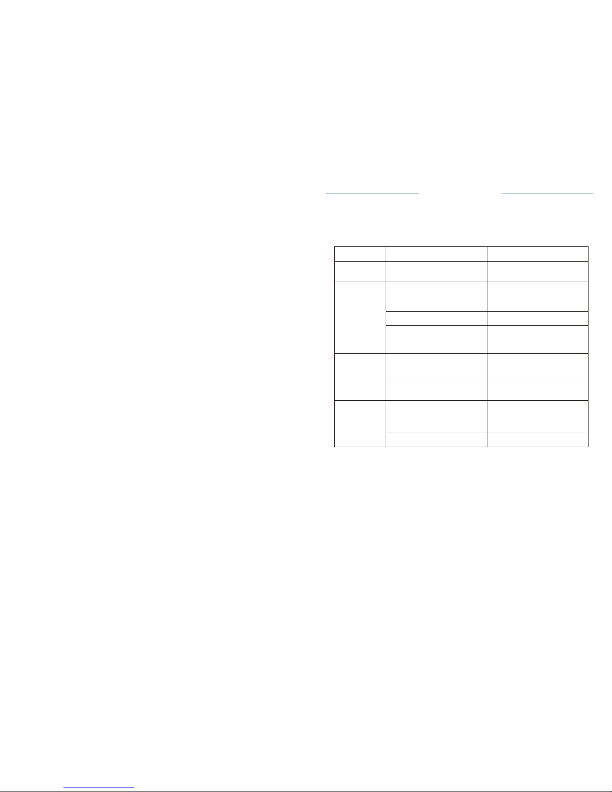
Problem
Cause
Solution
The power
is
not turned
on.
The battery is
bad
.
Change the
battery
.
The
motor
handpiece
does
not
rotate
The motor handpiece or
the
motor handpiece cord
Is
damaged.
Contact your
distributor.
The contra-angle is
clogged.
Clean or replace
the
contra-angle.
There is a short circuit
inside
the motor handpiece or
the
motor handpiece
cord.
Contact your
distributor.
Apex
measurement
is not
correct.
The file has no contact
with
the handpiece or file
holder
correctly.
Check the
connection
between the file and the
file
holder, clean it if
necessary.
Motor or test wire is
not
properly
connected.
Check the
connection.
File blocks
in
the root
canal.
Wrong file
setting.
Too much pressure on
the
instrument.
Change the
rotational
direction. Start the
motor
and pull out the file
carefully.
File not frequently
cleaned.
Clean the file
frequently.
8_3
Operation·
........................
·······
........................···14
8.3.1 M2 Apex locator
only(without
motor.)·
..........................
14
0
Troubleshooting
C-SMART-1
Pro Uoer
Manual
8.3.2 M2 Motor only (without apex
locator
)··············· ·· ·· ·· ·· ···
·22
8.3.3 M3 Motor and Apex locator (Dual
mode)·· ·· ····· ·· ·· ·· ····· ··
·28
8.4 Functional check of the apex
locator································31
8.5
Calibration
....................
·········
........................
······ 33
8.6 Factory Default Parameters-
......
·········
........................·36
If the device is not working
properly, please check the following table
before
calling our service
center.
9
Maintenance, Cleaning
and
Disinfection············
·37
9.1
General...................
········
.......................
········
.....37
9.2
Cleaning,
Disinfection and
Sterilization·· ·· ··· ·· ·· ··· ·· ··· ·· ····· ···38
(according to DIN EN ISO
17664)
9.2.1
Pre-treatment· ·· ····· ·· ····· ·· ·· ·· ··· ·· ·· ·· ····················· 38
9.2.2
ManualCleaning
and
Disinfection·· ······· ·· ·· ·· ·· ······· ·· ·· ·
·38
9.2.3
Inspection/Maintenance
.......................................38
9.2.4
Packing·
......
·········
........................
·········
........
39
9.2.5
Sterilization·
..................
·········
......................
···
39
9.2.6 Storage
......................................................... 40
9.2.7 Material
Resistance·· ·· ·· ·· ·· ·· ·· ·· ·· ··········· ·· ·· ·· ·· ·· ·· ·· ·
40
10
Troubleshooting ········· ..· ..
··· ...... ·· ...... ·· ..·..
41
11
Guarantee .
...........................................
42
12
Technical services
..................................
·42
Ill
Page 7
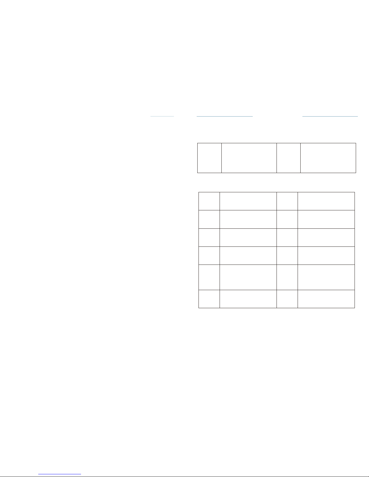
WARRING
CAUTION
If the instructions are
not
being followed
properly
,
operation may result
in
hazards for the
product
or the
user/patient.
c::r
NOTE
Additional
information,
explanation on
operation
and
performance.
I
Lori
Lot
number
[]]
Refer
to the
operation
manual
Ill
Manufacturer
Fragile
===
Direct
current
Caution
[QJ
Class II
product
Keep
dry!
Type B applied
part
:a
-
Special disposal of
waste
electrical and
electronic
equipment
(
Directive
2002/96/EEC)
IECIREPI
European Union
agent
( E:ol
97
CE marked
product
C-SMART-IPro
U11er Manual
C-SMART-1
Pro Uoer
Manual
• The rapid
Sterilization
method or the
Sterilization
method of
unpacked
accessories is not
permitted.
•
Also do not use any hot air
Sterilization,no
radiation
Sterilization,
no
formaldehyde or ethylene oxide
Sterilization
and no plasma
Sterilization.
9.2.6
Storage
After
Sterilization,
the instruments must be stored in the
Sterilization
package and kept dry and
dust-free.
1 General
Information
1.1Symbols
used in these
operation manual
9.2.7
Material Resistance
When selecting the cleaning and disinfecting agents, please ensure
that
they do not contain phenol, strong acids or strong aldehyde
disinfectants
or
anticorrosion
solutions. The material is resistant up to 137 °C/279 °F
(maximum exposure
temperature).
1.2
Symbols used
on
Packaging,Device
and Parts
'
*
II
Page 8
2
Indications
for
use
C·SM ART·IPro
Usar
Manual
C-SMART-1
Pro User
Manual
o
Then
remove
the
accessories
from the
disinfection
bath and rinse
them
thoroughly
with water for at least five times for 1
min.and
press and
release
The
device
is the
supplementary root-canal
treatment
device which can
assist
the
dentists
to shape more
standard root-canal
in the
process
of
root-canal
treatment
based on the
micro-electronic
control technology.
This
instrument
contributes
to
alleviate
the
dentist's working intensity.
This
device
must only be used in
hospital
environments, clinics
or dental
offices
by
qualified
dental
personnel.
3
Contraindication&
o
In cases where a
patient
has been fitted with an
implanted
heart
pacemaker
(or other
electrical equipment)
and has been
cautioned
against
the use of
small
electrical appliances
(such as
electric shavers,
hair
dryers, etc.) it is
recommended
not to use the
device.
o The
device
should not be used for
severely curved
root canal
preparation.
o
Do not use the
device
for
implant
or any other
dentist procedure outside
endodontics.
f4
Warnings
The
device
must only be used in
suitable locations
and only by
specialized
physicians licensed
to
practice dentistry.
In this
chapter, a description
of
serious adverse reactions
and
potential safety
hazards
for the
product
or the
user/patient
is
included.
Read the
following
warnings
before
use.
WARNINGS
o The device must only be used in
suitable locations
and only by
specialized
physicians licensed
to
practice
dentistry.
o Confirm that the
operating
voltage and the mains voltage are
compatible.
•
Use the specified battery for this
product.
Never use a battery other
than
those
specified
by
manufacturer.
o
Use the
manufacturer AC adapter for this
product.
Never use any other AC
adapters.
o
If you do not use the device for a long period of
time,remove
the battery
to
avoid fluid
leak.
o
If you
should
notice battery fluid leak,
deformation
of the motor
handpiece
casing or partial
discoloring, immediately
stop use and contact your
distributor
II
the file clip five
times. Inspect,
dry and pack the
accessories
as
quickly as
possible
after
removal (see chapter INSPECTION,
and
PACKING).
Please
make sure that the
accessories
do not have direct
contact.
9.2.3
Inspection/Maintenance
Check all
accessories
after
cleaning
or
cleaning
I disinfection. Defective
accessories
should
be
immediately discarded.
These
defects include:
• Plastic
deformation
·Corrosion
Accessories
which are still
contaminated
must be
cleaned
and
disinfected
again.
Maintenance
is not
required. Instruments
oil must not be
used.
9.2.4
Packing
Please
pack the
accessories
into
disposable Sterilization packages
(single
disposable packaging) meeting
the
following requirements:
•Compliant
with DIN EN
ISOIANSIAAMIISO 11607
·Suitable
for steam
Sterilization
9.2.5
Sterilization
Use only the
Sterilization methods
listed
below; other
Sterilization
methods are
not
permitted.
• Steam
Sterilization
•
Fractional vacuum/pre-vacuum
(at
least
three
vacuum cycles)
method
or
gravity displacement
method
(product
must be
sufficiently
dry).
The less
effective gravitational
method should only be used if the
fractional
vacuum
method is not
available.
·Steam
sterilizer
according
to DlN EN 13060 or DIN EN
285.
·The Sterilization validation
has been
performed
in
compliance
with DIN
EN
ISO 17665 (Valid
installation and
operation qualification
(IQ and OQ)
and
product-specific performance qualification (PQ).
•
Maximum Sterilization temperature
134
ac
(273
GF);
plus tolerance
according to
ISO DIN EN ISO
17665.
·Sterilization
time (exposure time
at
Sterilization
temperatura) at
least
18
min.at
134 •c (273
aF).
Page 9

C-SMART-IPro
U11er Manual
9.2
Cleaning,Disinfection
and
Sterilization
(according
to DIN EN ISO
17664)
The
procedure
for
cleaning,
disinfection
and
Sterilization applies
only to
the
Lt.
WARNINGS
C-SMART·IPro Uoe r
Manual
accessories
lip hook, file clip and
contra-angle.
9. 2.
1 Pre-treatment
Pulp and
dentin
residues
must be
removed immediately
from the
accessories
(within maximum
2 hrs). Do not let them
dry!After
the
accessories
have
been
used on
patients,
place the
accessories
for
cleaning,pre-disinfection
and
interim storage directly
into a bowl filled with an
appropriate cleaning and
disinfecting solution
(for max. 2 hrs). Then clean the
accessories under
running
water or clean in a
disinfecting solution
to remove all
visible
contamination.
The
disinfectant should
be
aldehyde-free (aldehyde
fixes
blood stains),tested
for
effectiveness
(e.g. CE
mark), suitable for
accessories disinfection
and
compatible
with the
accessories. Only
use
clean, soft
brushes
to
manually
remove
contamination
or a
clean,
soft cloth which you only use for this
purpose.
Do not use metal
brushes
or
steelwool.
For
better cleaning
of the inner parts, the file clip must be
pressed
and
released
five times during
cleaning process. Please
note
that
disinfectants
used for
pre-treatment
are only for
personal
protection
and
do
not
replace disinfection
when
cleaning
is
completed.
The
pre-treatment
process
should be
performed
in every
case.
.&.
CAUTION
Do not use an
automated procedure
or
ultrasonic
bath to
clean
or
disinfect
the
accessories.
9.2. 2 ManualCleaning
and
Disinfection
Cleaning
•
Place the
pre-cleaned accessories
into the
cleaning
bath for the
prescribed
contact
time, the
accessories
must be
sufficiently covered
(if
necessary careful
brushing
with a soft
brush).
For better
cleaning
of the inner
parts,the
file
clip
must be
pressed
and
released
five times
during cleaning process.
·Then
remove the
instruments
from the
cleaning
bath and rinse them
thoroughly
with water for at least three times for 1 min. and press and
release
the file
clip
five
times.
Disinfection
·Place
the
cleaned
and
inspected accessories
into the
disinfection
bath
for
the
prescribed contact
time; the
accessories
must be
sufficiently covered.
For better
disinfection
of the inner
parts,
the file clip must be
pressed and
released
five times
during disinfection process.
• Do not
disassem ble
or alter the motor
handpiece.
• Do not
expose
the
unit,motor handpiece
or
battery charger
to any
liquid.
• Do not
expose
the device to
direct
or
indirect sources
of heat.
Operate and
store the device in a safe
environment.
• Do not drop the
device.
• In order to avoid
possible
risks due to
electromagnetic interference,
do
not
use any
electrical
medical device
or
electrical
device of any other kind
in
close
proximity
to the
device.
• The
device
may
possibly malfunction if
used in the
presence
of an
electromagnetic interference
wave. Do not
install
the
device
in the
vicinity
of any
device
that emits
magnetic waves.
• Do not use the device in the
presence
of free
oxygen
or
anesthetic
substances
or
flammable
products.
• None of the
device components
are
delivered disinfected
or
sterilized:
components
such as control
unit,motor
and motor cable need to
be
disinfected,the contra-angle
and Lip hook needs to be
sterilized
prior
to
first use and in
between
each
patient!
• The
plastic enclosure
is not
sealed, do not use any
liquid
or spray
directly
on the unit,
especially
on the
monitor
or near the
electrical sockets.
•
Follow
the file
manufacturer's instructions
for use of the
endodontic
files.
• The file
system
shown on the
display
must always match the file in use.
This
is of the utmost
importance
in order to
avoid misusing reciprocating
files
and
continuous
rotary
files.
II
Page 10
C-SMART-1 Pro Uaer Menual
C-SMAI[J-J Pro
u
..
r M•nuel
5
Precautions
9 Maintenance, Cleaning and
Disinfection
• Read these safety precautions thoroughly prior to
use.These precautions
allow
you to use the product safely, preventing harm to you and
others.
• Refer to the WARNINGS chapter to verify any special care to exercise
before
starting to use the complete
device.
• Before changing the
contra-angle
or file, turn off the power of the unit.
Changing
with the power kept on may cause unintended rotation by
accidentaltouch of
the
ON/OFF
key.
• Always clean the shank
ofthe
file to be
installed.Allowing
dirt to enter the
chuck
could cause loss of
concentricity
and
deterioration
of chucking
force.
• Pay attention to the direction of the battery connector when
installing.
Forcible
setting In the wrong direction may cause damage and fluid leakage due to
a
short
circuit.
• Fully-charged
rechargeable
batteries generally discharge gradually over
time
even though the device is not used. It is recommended to recharge the
battery
just before
use.
• When disposing of the control unit, follow the
instructions
of your
local
government for disposal, as they contain materials which may become
industrial
waste.
• This product does not consider a patient's age,
gender, weight or
nationality.
The manufacturer declines any
responsibility
in the case
of:
• Use of the device for applications other than those specified In the
instructions
for use and
maintenance.
• Modifications or repairs performed by persons not authorized by
the
manufacturer.
·Use
of
non-original
components or components other than those specified in
the
Standard Components chapter_
• File breakage due to
missus
• Accessories or device breakages due to
sterilization:
none of the
device
components are
sterilizable
(except for the
contra-angle).
6 Adverse
Reactions
There are no known adverse
reactions.
II
9.1
General
The device is maintenance free and does not contain user serviceable
parts.
CJ='NOTE
Service and repair should be provided by factory trained service
personnel
only.
• The surface of the device , test wire ,lip hook wire, motor cable and
lighting
device should be cleaned using tissue or soft cloth soaked with aldehyde
free
disinfecting and detergent solution
(bactericidal
and
fungicidal).
&cAUTION
• Wipe The surface
ofthe
device , test wire ,lip hook
wire,motor
cable
and
lighting device with a clean
cloth,lightly
moistened with a
non-aggressive
disinfectant.
• Do not apply any liquid or spray directly on the
device,especially on
the
display.
• Do not use high-proof alcohol for di
sinfection.
• The accessories lip
hook,
file clip and contra-angle must be cleaned,
disinfected
and sterilized prior to each
use_
Thorough cleaning and disinfection are
essential
prerequisites
for effective
Sterilization.The
specific Instructions for
cleaning/
Sterilization
must be applied according to the
Instructions
in chapter 9.2
·cleaning,
Disinfection
and
Sterilization•.
In
addition,the
operating
instructions
of
the
devices used in your practice must be followed.As part of your
responsib
ility for
accessories
sterility, always ensure that only
validated methods for
cleaning
/
disinfection
and
Sterilization
are used, that devices
(disinfector,sterilizer) are
regularly maintained and inspected and that the validated parameters
are
maintained with each
cycle.
• In
addition, always observe the validated legal regulations and
regulations on
hygiene relating to your practice or the hospitaL This applies in particular to
the
guidelines regarding effective prion
inactivation.
• For your own safety, always wear protective gloves, glasses, mask
when
handling contaminated
accessories.
Page 11
=b.....
-
C-SMART-IPro
Usar
Manual
8.6
Factory Default Parameters
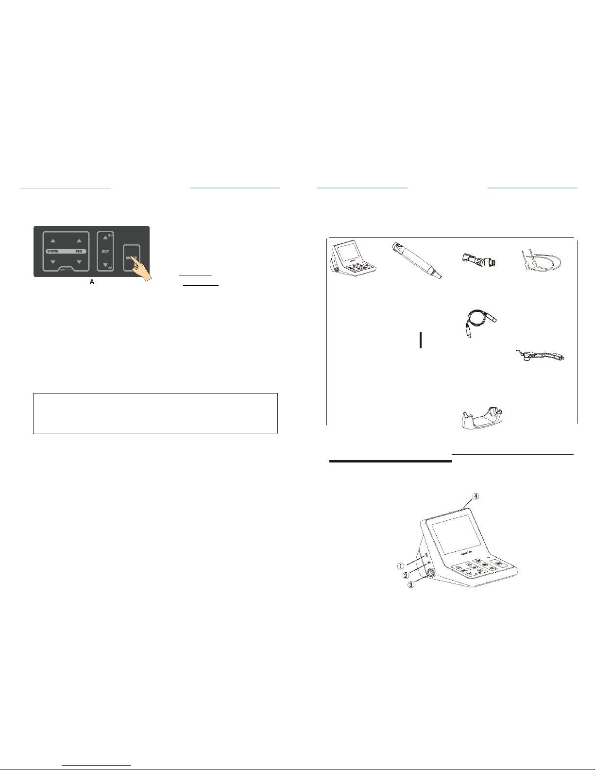
To return to the
original
default
parameters,
follow the
general
reset
instructions:
@
SETUP
C-SMART-1
Pro Uoar
Manual
Components, installation
and
charging
7.1
Standard Components
A
EI. Intlllhnml•r gu•l•
A
: :!
'!!
IIAute-n•IIKMM
F
!!!n.ht
!
:c
dlll)
'·-
8
:=-.....
....
B
• Press the SET key to enter the RESET
state;
Engliah
•
ON
•
ON •
Control unit
Motor
handpiece
#I
Contra
angle
(
External)
File
clip
• Press the MODE key for 2
seconds
(A) to enter setting
interface;
• Press Up or Down key to select RESET
(B);
• When the
factory
reset is
complete,
the
display returns
to the M1
interface.
.&.
CAUTION
Please
note: when the
factory settings
are
restored,
all
personal settings
Lip hook
Test
wire
Lip hook
wire
Lighting
device
D
will be
lost.
'
Handpiece stand
Operation Manual
Tester
AC
adapter
7.2
Structure
CD
Charging
socket I test wire
socket
® Lip hook wire
socket
@ Motor
handpiece socket
@ Power
button
Page 12

Fig.1
II
Page 13
C-SMART-IPro
Usar Man ual
C-SMART-1
Pro Uoar
Manual
7.3 How
to connect
each
part
CAUTIONS
Do not pull on the wire when removing the part with the
wire.
L._
i
error
7.3.1Connecting
and
Disconnecting
the
Motor Handpiece
a. Connecting
Align
the--
mark of the cord plug with the notch of the motor handpiece
socket
(see
Fig.)()()()
at the left
side
of the
device
and
insert
the
plug until it locks.
b.
Disconnecting
Hold the plug ring and pull it out. Do not twist in any
direction.
7.3.2
Connecting and Disconnecting
the
Contra angle
a.Connecting
The contra angle can be connected at 6 adjustable head
positions.Align
the
positioning
pins of the contra angle with the
positioning
slots of
the
motor handpiece and insert the head until it
clicks.
b.
Disconnecting
When removing the contra angle, pull it straight
out.
CAUTIONS
• When connecting and disconnecting the contra angle, turn the power
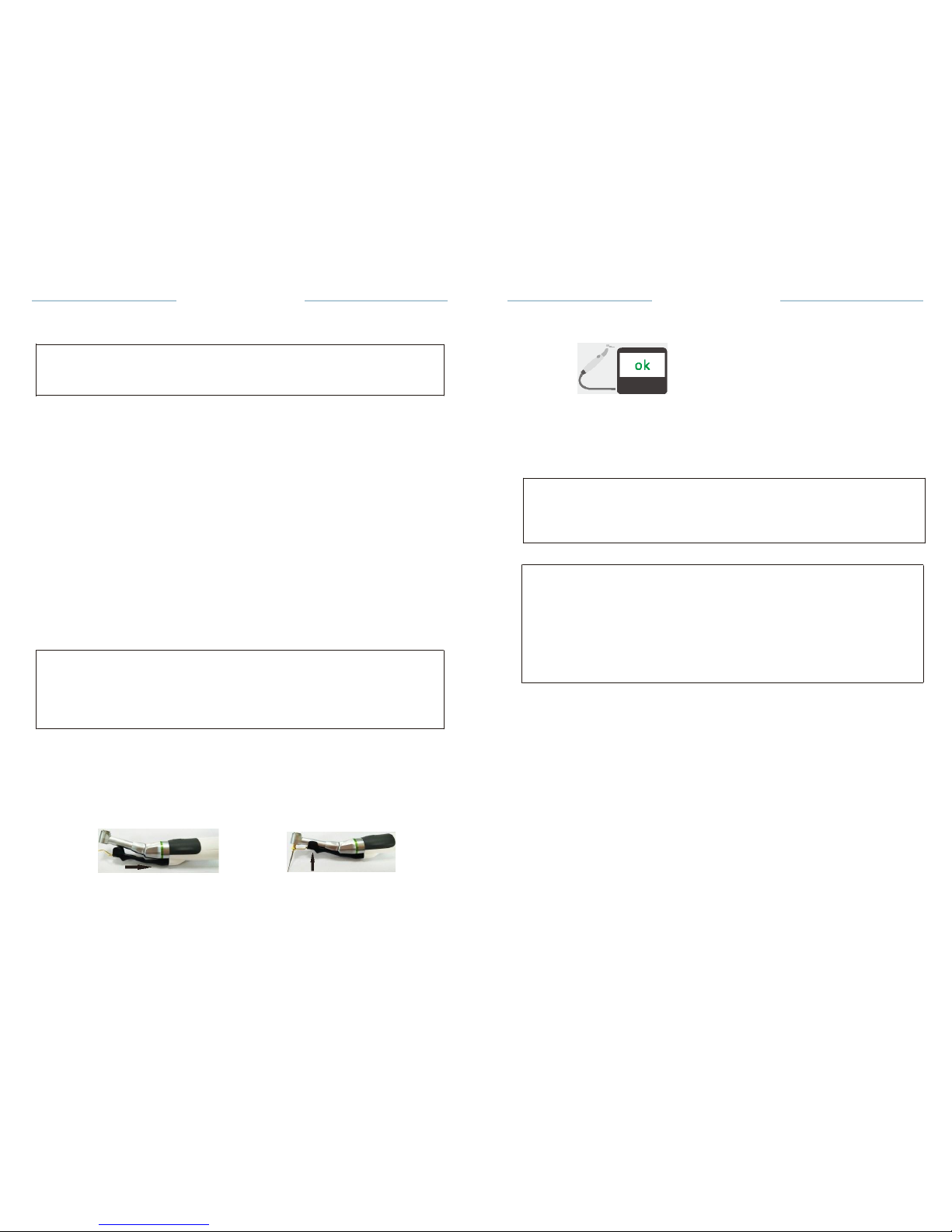
off
beforehand.
• Check that the contra angle is securely assembled to the motor
handpiece.
Fig.39
Contra-angle
is OK
Fig. 40
Contra-angle
is ERROR
!Lt.
CAUTION
ERROR message indicates that the contra-angle is not operating
properly
Please contact your local dealer or contact the factory directly for
assistance
r::.7'
NOTE
Should you at any time wish to stop the calibration process, turn the power
oft.
Calibrate every time the contra angle is lubricated or replaced after sterilizing
,
or at least once a week
(Lubricating
the Contra angle , Cleaning
,Disinfection
and
Sterilization
see the operation manual of contra
angle).
Do not touch or apply a load to the contra angle chuck during
calibration.
7.3.3
Inserting and Removing
the
lighting device
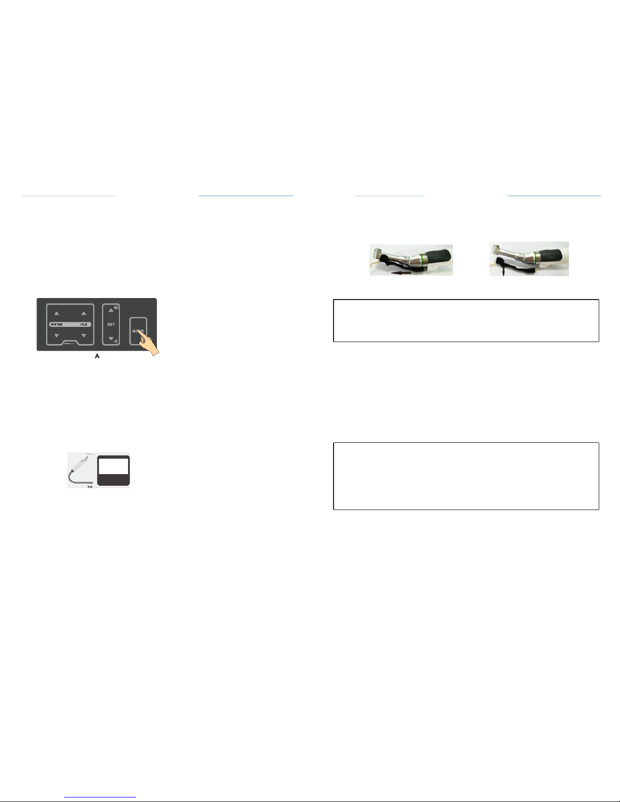
a.
Inserting
Insert the lighting device into the motor
handpiece(Fig.2),
clamp the
contra
angle and
file(Fig.3).
Fig.2
Fig.3
Page 14
0
e
8.5
Calibration
C-SMART·
l Pro Uaar
Manual
b.
Removing
C-SMART·IPro Uoa r
Manual
This
function
is to
decrease fluctuation
in the
rotation
speed of the
motor
handpiece
and the
difference
in
torque
by the contra
angle.
Calibration
is
recommended
when using a
new/other contra
angle or
after
an
extended
period of
operation,
as the
running properties
can change
with
usage, cleaning
and
sterilization.
Sliding
it in the
direction
of the socket and then
removed
with
contra-angle,
Otherwise
it will be
damaged.
The
calibration
steps as
follows:
·Turn
the power
on.
0
SETUP
.&.
Fig.4
Fig.5
A
ld. .,.MII"' ·
A .,...-
. ·
;
.tit
,. ' i tt: lLE
EDdiiiJt!Mt.
: T torvw
Engllah
•
ON
•
ON •
CAUTIONS
When
inserting
and
removing, please
do not
shake,
so as not to
damage
the
plug.
8 =torNWI,.fMIGIIJMtlll'll
B
• Press the MODE key for 2
seconds
(A) to enter
setting interface;
• Press Up or Down key to select
calibration (B);
·Press
the SET key to enter the
calibration state:
• The
screen
will be
prompted
to insert the motor
handpice (Fig.37);
•
During
the
calibration process
the
display
will read
(Fig.38):
7.3.4
Inserting
and
Removing
the
Fila
a. File
insertion
• Insert the file into the chuck until it
stops.
•
Lightly
turn the file until
it engages
with the
latch mechanism. Push
inwards
to
click.
b. File
removal
Press the
push-key
and pull out the
file
.
_,
r:::-1
0
0
.
-
.&.
CAUTIONS
•
When
attaching
and
detaching
the file, turn the power off
beforehand.
•
After the file is
locked
in
place, lightly
pull out the file to make sure the
file
is
locked.
•
Always
clean
the shank of the file to be
installed.Allowing
dirt to enter
the
chuck could cause
deterioration
of
chucking
force.
Fig. 37 Insert the motor
handpice
Fig. 38
Cerebration state
·The
motor
handpiece
begins to
rotate: leave
it as
it
is until
it stops.
·When
the
calibration process
is
completed,the rotation
stops and
the
display reads:
·Then,
the
display returns
to its
originalstate.
II
Page 15
C-SMART-IPro
Uaer
Manual
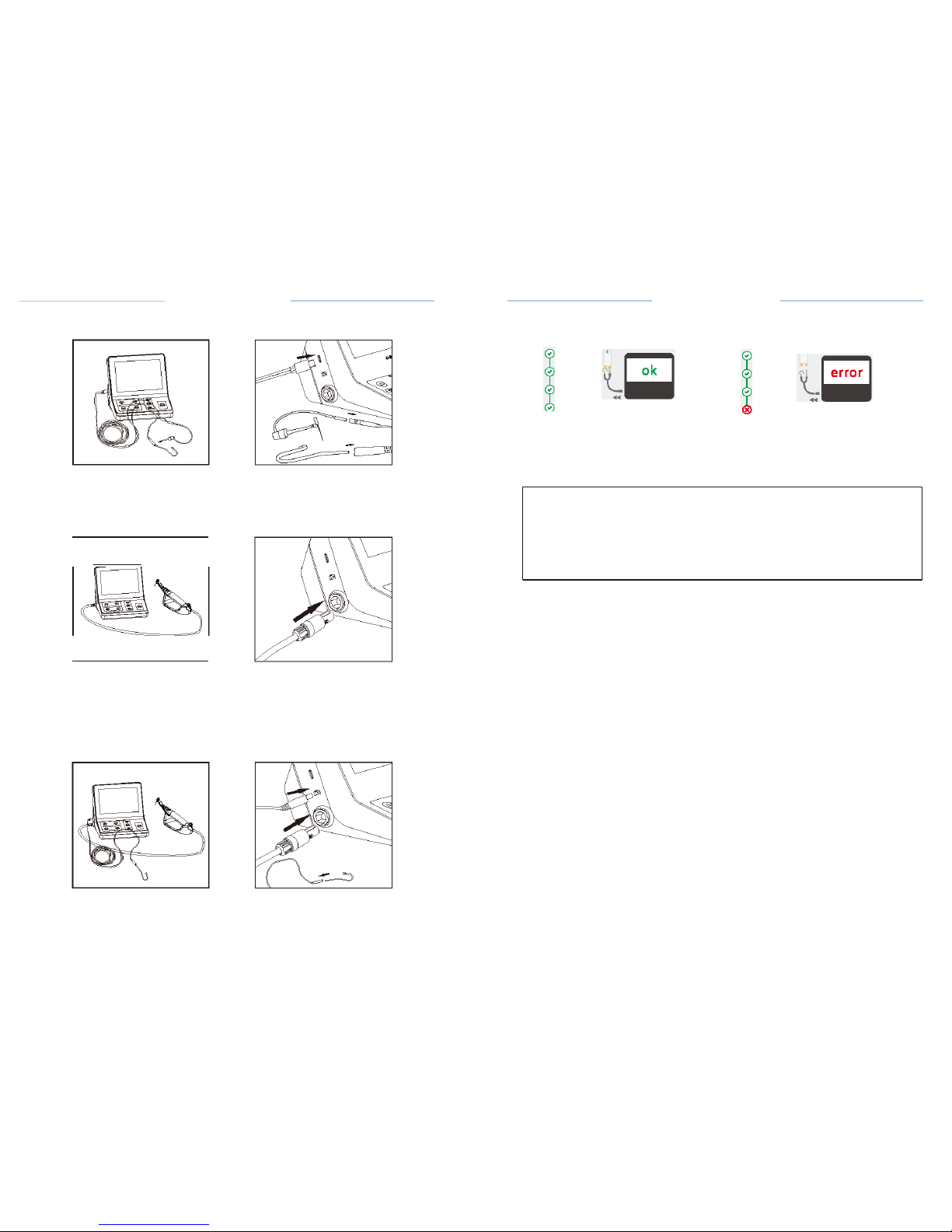
7.3.5 M1 mode
connection (only
apex
locator function)
C-SMART-1
Pro Uoer
Manual
Fig. 35 Accessories are OK
Fig.36 Accessories are ERROR
Fig.6
Fig.7
Connect the test wire with lip hook and the File clip to the Control unit,
test
wire's plug must be fully inserted into the test wire
socket.
Lt.
CAUTION
7.3.6 M2mode
connection (only motor function)
Fig.B
Fig.9
• Connect the motor cable to the
Controlunit's
motor handpiece
socket.
• Connect the contra angle to motor
handpiece.
•Install
the lighting
device.
•Insert
the
file.
7.3.7 M3 mode
connection(Dual
mode
Motor&Apex
locator)
Fig.10
Fig.11
ERROR message indicates that the accessories are not functioning
properly
(wire breakage) or the contact area is
dirty.
Please contact your local dealer or contact the factory directly for
assistance
CHECK mode will exit automatically after 3s .
Page 16
C-SMART-I Pro
U11er Manual
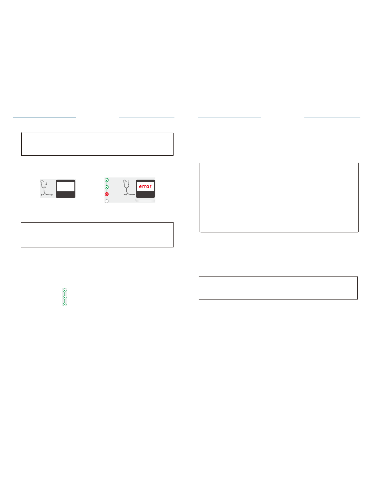
Test Wire Functional CHECK
NOTE
If the device functional CHECK is OK, then you have to proceed to
the
cables
functional
CHECK.
Connect the test wire to the device
(Fig.32).
0
0
Fig. 32 Connect the test wire
Fig.33 Test wire is ERROR
.&.
CAUTION
ERROR message indicates that the test wire is not operating properly.
Please contact your local dealer or contact the factory directly for assistance.
• Insert the File clip and lip hook (or replace the lip hook with another File
clip)
in the test
wire.
• Connect File clip and lip clip (or a second File clip) to the contact strips
on
the tester as shown on the screen(Fig.
34).
't.
0
Fig.34 Connect
tester
• Cables CHECK will start
automatically
and the
results- either OK (Fig.
35)
or ERROR (Fig.
36)-
will be shown on the
screen.
C-SMART·IPro
User
Manual
• Connect the motor cable to the Control unit's motor
socket.
• Connect the contra angle to the motor handpiece and insert the
file.
• Install the lighting device and catch the
file.
• Connect the lip hook wire to the Control unit and connect the lip
hook.
7.4
Changing
the
Battery
.&.
CAUTIONS
PRECAUTIONS ON CHANGING BATTERY:
• Do not open any part other than the battery
cover
• Be sure to purchase and use only the recommended
battery. Otherwise,
battery may cause
damage,fluid
leakage or
explode.
• Ensure that the AC adapter is disconnected and turn off before
changing
the
battery.
• Do not change the battery with wet hands as this may cause
short-circuiting
of the battery and moisture infiltrating the
device.
• The used battery must be disposed of in accordance with the
local
regulations.
• Turn the power
off
•
Disconnect the AC
adapter.
•
Remove the screw from the cover with a screw driver, and remove
the
battery
cover.
• Insert the battery cord connector into the device connector in
accordance
with the polarity indication inside the battery compartment and place
the
battery into the compartment with care so as not to catch the
cord.
NOTE
In case of difficulty in inserting the
connector,the
polarity may be
incorrect.
Do not insert it by
force.
• Close the battery cover and lock the
screws.
•If
you need to replace the battery,remove the battery and unplug
the
battery
connector.
.&.
CAUTIONS
When removing the battery cord, make sure to hold it at the
connector.
Failure to do so may damage the
cord.
II
Page 17
7.5
Charging
C-SMART-I Pro
U11er
Manual
C-SMART-1
Pro User
Manual
8.4 Functional check of the apex
locator
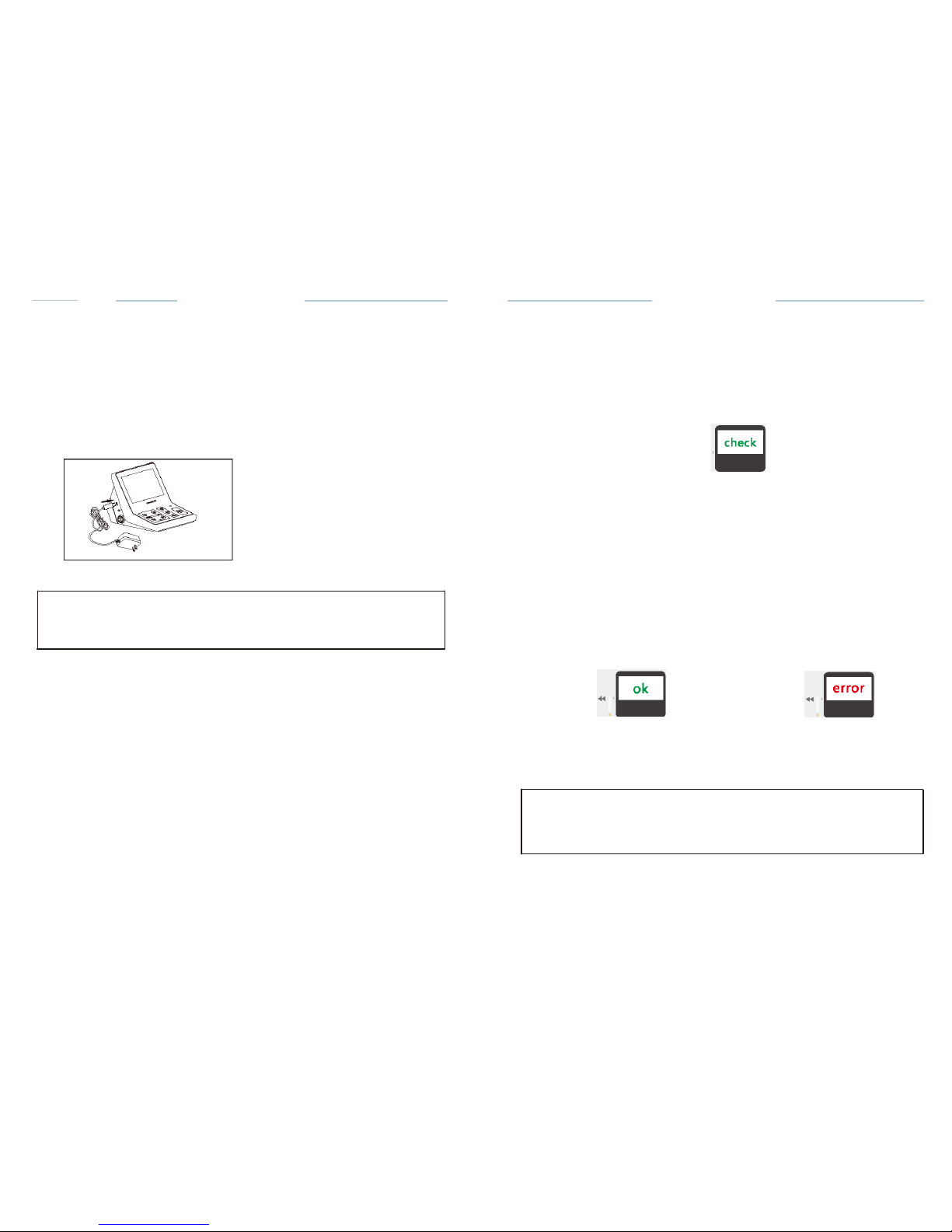
Charge the
battery according
to the
following steps:
• Connect
the
charger's connector
to the
Control unit's charging socket
G)
(Fig.
12).
• Connect
the plug of the
charger
to a power
outlet
• It
takes about 4 hours to fully
charge
and about 5 hours for fully
discharged
batteries (E.g.,
the
device
is not used for a long
time).
•
When
charging,
the
charging
status will be
displayed
on the
screen.
(Fig.13)
7-0%
Fig.12
Fig.13
r:::T
NOTE
In case of
difficulty
in
inserting
the
connector,
the
polarity
may be
incorrect
Do not insert
it
by
force.
It is
recommended
to check the
performance
of the Apex
Locator
once a
week.
With the
built-in inspection
function,
the
special
test plug can
automatically
check the basic
functions
of the
instrument
in the first step, and then
inspect the
accessories
in the second step (Fig.
29).
e
0
0
0
Fig.29
Device
inspection
The
specific
steps to use the check
function , as
follows:
• Disconnect
the test wire,
adaptor and motor
handpiece
from the
device.
·Device
CHECK will start
automatically if
the tester
inserted
in the
device and
the
results
will be shown on the
screen.
• Display
shows OK (Fig. 30)
,Indicates
that the device
function
is
normal.
·Display
shows ERROR (Fig_
31),Indicates
that there is a
fault
0
0
0
0
Fig.30 Device
is OK
Fig.31 Device
is
ERROR
.&.
CAUTION
ERROR
message indicates
that the
device
is not
operating properly.
Please
contact
your local
dealer
or
contact
the
factory directly
for assistance_
•
Disconnect
the tester from the
device
and
prepare
the test of the wire
with
accessories.
Ill
Page 18
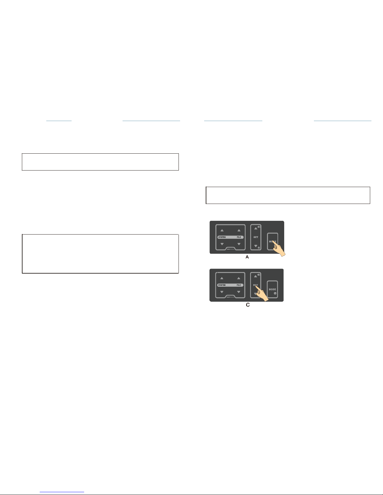
Torque
bar
C-SMART-IPro
U11er Manual
C-SMART·IPro Uoe r
Manual
8 Step by step
instructions
When the motor handpiece starts and its load reaches approximately half of
the preset torque limit value, the torque bar display••••• ,when the
load
approaches the torque limit value, the torque bar displaY •••••
II.
r:::.7'
NOTE
This function is only available in continuous rotary file
system.
Working length
determination
o
In M3 mode,As soon as the file makes contact with the root
canal,the length
measurement is started. During the apex area, with further progression
of
the file in the root canal, the numerical value on the graphical scale
changes.
The unit emits
audible.
o When the file tip reaches the DR'S CHOICE apex
position,it
indicates
that
the apex is reached. The motor
automatically
reverses or stops
depending
on the selected auto reverse
mode.
8.1
Language,LCD Paneland Operation Panel
8.1.1
Switch-on and Switch-off
the
Unit
o Hold down the POWER
button@
(Fig. 1)for more than 2
seconds.
A welcome screen is
displayed.Then,
the display will return to the
last
mode before switching the device
off.
o Press the POWER button again to turn off the
power.
r:::.7'
NOTE
If 5 minutes pass without operation, the power turns off
automatically.
8.1.2
Language Select
@I
SETUP
&cAUTION
Do not forget to connect the lip clip to the patient prior to
measurement.
Occasionally, the graphical scale will make a sudden drop as soon as
the
file is inserted into the root canal, but it will return to normal state as the file
is advanced down towards the
apex.
8.3.3.9 Functional check of the apex
locator
It is recommended to check the performance
ofthe Apex Locator once
a
week. the detailed check methods, see Chapter 8.4 .
A
..
o:td'"-"1'"'
'
'
'
"'"
IR
!
AIIIO-
ruMtMi
e
;; :fg:ht
:dE..
.,-ttrn&
RKJ .....
u•
El
!!E iD
...... IMfi"l
B
English
•
ON
•
ON •
o Press the MODE key for 2 seconds (A) to enter setting interface
(B);
o Press the SET key to select the desired language
(C);
o
The change will be saved automatically. Press any key other than SET and
up or down key to exit the setting, or exit the setting
automatically
after
3
seconds.
m
Page 19
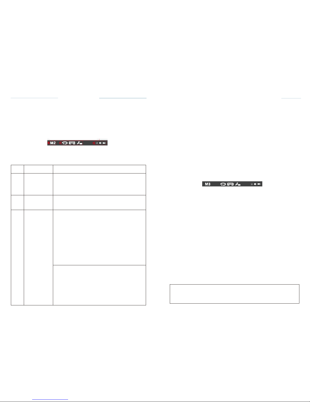
A
Working
area
Displays operating parameters
in
different modes.
B
Mode
area
The device can be
operated
in three
different modes:
M1: Apex
locator only,
M2: Motor
only,
M3:
(Dualmode)
Motor with apex
location
function.
c
Motor
option
area
Display
motor
rotation direction,
auto
reverse,
lighting
and LED delay
time.
*M2 and M3 are
available
D
Status
area
BATTERYdisplays
the
present remaining
amount
of
the
battery :
CJJ
Full
charge
[-!!]
Less than 30%
remains.
E:!]
Approximately
30-80%
remains.
The
remaining amount
of
battery mark
indicates
a
voltage
. When a load is
applied
to the
motor
handpiece,
there
remaining amount
of
battery
mark
appear
to be come
lower.
SOUND
VOLUME displays
the
current
sound
volume
(see
chapter
6.5.7. Sound Volume
Adjustment).
4 marks can be
displayed:
OJ
High
volume
rm
Low
volume
Minimum
volume
1:1
Limited
off
I
C-SMART-
l Pro Uaar Ma nual
C-SMART-lPro Uoar
Manual
8.1.3 LCD
Panel
,---------------- ---------------
-
1
SYSTEM:
CI!Mwo
SPEED:
I
Wave
0
150
..
m
l
FlU: TORQUE
liJ ID
IDCKJ 0.6 N<m
I
@J@J
: •••••
II
Fig.14
LCD
Panel
8.3.3.5 Changing Speed,
Torque and set
Changing
Speed and
Torque
• See
8.3.2.5 Changing
Speed and
Torque
Set the DR'S CHOICE apex
position
Follow
these steps to set the DR'S CHOICE apex
position:
•
Press the SET key, the apex
setting
icon
becomes adjustable
state,(Fig.28)
·Press
the Up or Down key to
adjust
the apex
position.
Path File
·-
0
•pm
SYSTEM:
l:loaru-
SPEED!
15
Fn.E:
0.6
••m
·Cill
mm
mCill
•••••
I l
-
8.3.3.6
Auto
Reverse
Fig.28
Set Apex
Position
Battery
is
drained
or very low
battery voltage.
Charge the
battery.
r::::7'
NOTE:
See
2.3.2.6
Auto
Reverse
8.3.3.7
LED
lighting function
See
2.3.2.7
LED
lighting function
8.3.3.8 Working
Start and stop the Motor
handpiece
The motor is
started
and
stopped
with the ON/OFF key on the
handpiece.
fyou
press the
ON/OFF
key briefly, the motor
handpiece
starts.
If you
re-press
the key,
it stops.
Reverse
Press the on I off
button
for more than 2
seconds
to change the
direction
of
file
rotation (whether
the motor is
stopped
or
running).
The
current direction
of file
rotation
is
displayed
in the motor option
area.
Means
forward
rotation
Means
reverse rotation
r::::7'
NOTE
Only
continuous rotary
file
systems
can
change
the
direction;
reciprocating
file
systems
can not change the
direction.
Page 20
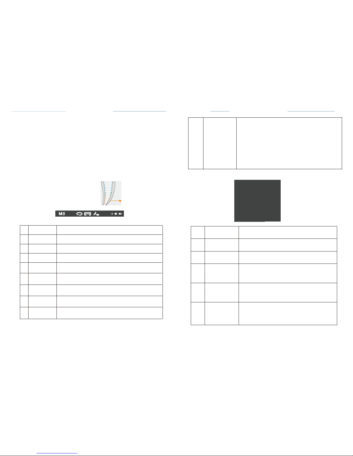
....
....
D
....
T
1
SYSTEM
See2.3.2.3
2
FILE
See2.3.2.3
3
SPEED
See2.3.2.3
4
TORQUE
See2.3.2.3
5
TORQUE
BAR
See2.3.2.3
6
ROTATIONAL
DIRECTION
See2.3.2.3
7
AUTO
REVERSE
See2.3.2.3
8
Motor
and
LED
lighting
See2.3.2.3
9
Root
apex
Area
Specially shows
the Root apex area
and
indicates where
the file
was
reached.
1
SYSTEM
.lit./,.
Change the file
system.
2
FILE
Change the file within a
system.
3
SET
Press this key to
adjust
the
different parameters.
4
[
...>> ]
a.Up
key
b.Adjust
the sound
volume(idle
state)
5
..
a. Down
key
b. Adjust the
screen brightness(idle
state)
6
[
•oo];
a. Short press to switch
between 3 operating
modes: Apex
Locator,
Motor, Dual
mode
b. Long press to enter setting
interface.
m
•
C-SMART-IPro
U11er Manual
8.3.3 M3
Motor
and Apex
locator {Dualmode)
Press mode key to enter M3 mode. In this mode, as a
combined unit
(Dual mode) when the apex
location function
drives the
endo-motor.
8.3.3.1 Connection
The
connection
method in this mode is shown in
chapter
7.3.7
Fig.1O,Fig. 11.
8.3.3.2 Calibration
Calibration
is
recommended
when using a new
contra angle,
the
detailed
calibration methods,
see
Chapter
8.5.
8.3.3.3 Working area
SYSTEM: S EEO:
150
,.m
C-SMART-1
Pro User
Manual
Screen
Brightness display
the
Brightness
of
the
screen (see
chapter 8.2.2.Screen Brightness
Adjustment).
4 marks can be
displayed
D
Status
area
n
brightest
bright
darker
dark
8.1.4
Operation Panel
Path
File
TORQUE
8
FD.E: 0.6
Ncm
Cill
mm
-
..... ll
Fig.27 M3
interface
Fig.15
Operation Panel
[
:;: [
8.3.3.4 System
and File
Select
See
8.3.2.4 System
and File
Select
Page 21
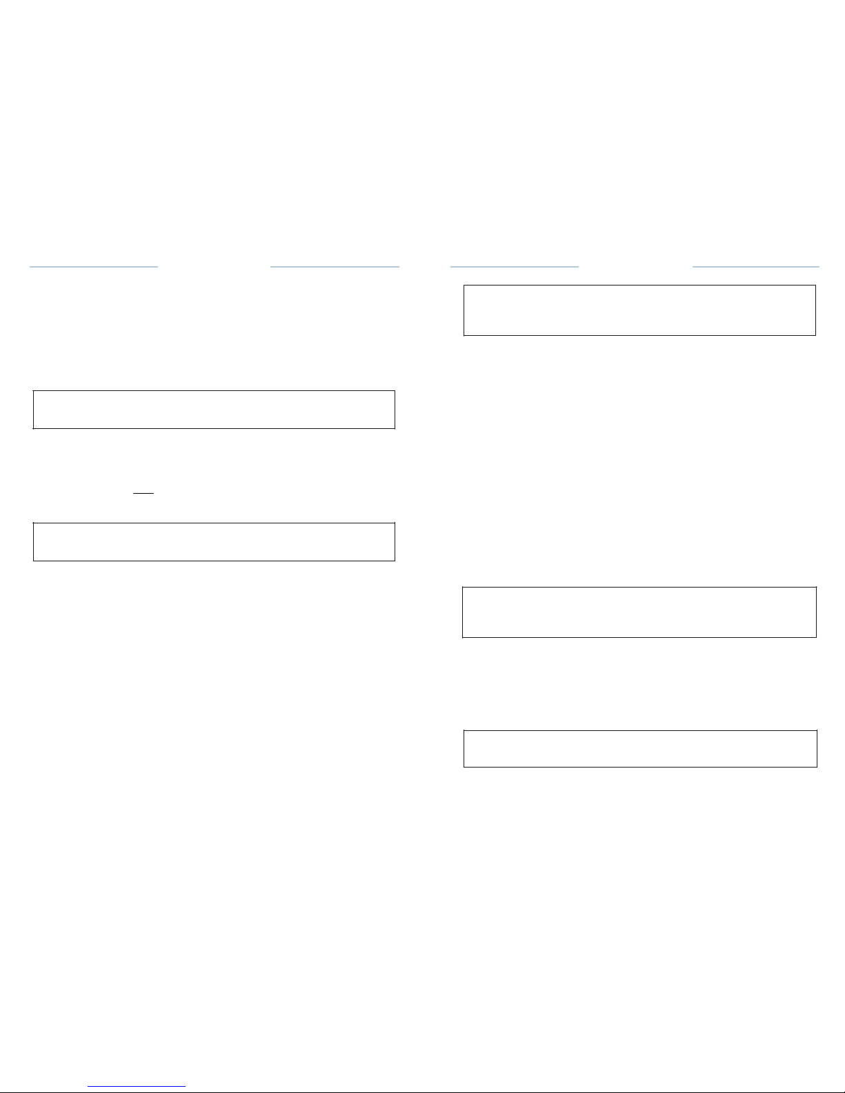
C-SMART-
l Pro Uaar
Manual
8.2
Sound Volume
and
Screen
Brightness Adjustment
r::7'
NOTE
C-SMART·lPro Uoar
Manual
8.2.1Sound Volume
Adjustment
The sound
volume
can be
adjusted
to 4
different levels:
high.
low,
Minimum
and
limited
off_
• Press the key 4
[._Ill,>]
in the idle state to
adjust
the sound
volume;
•
The sound
volume display
on the LCD panel
status area.
r::7'
NOTE
The last sound
volume
is
retained,
even
if
the power is turned
off.
8.2.2
Screen
Brightness
Adjustment
The Screen
Brightness
can be
adjusted
to 4
different
levels.
• Press the key 5
[•·:+:·]
in the idle state to
adjust
the screen
brightness;
• The Screen
Brightness display
on the LCD panel Status
area.
r::7'
NOTE
The last Screen
Brightness
Is
retained,
even If the power Is turned
off.
8.3
Operation
The
device
can be
operated
in three
different modes:
CDM1 apex
locator
only;
M2 Motoronly;
@M3 as a
combined
unit (Dual
mode)when
the apex
location function
drives the
endo-motor.
One of the three
possible operating
modes is
selected
with the MODE
key
6
i•oo;l.on
the
operating
panel, the mode number
display
on the LCD
panel
Mode
area.
8.3.1 M1
Apex locator only{wlthout
motor)
8.3.1.1 Connection
The
connection method
in this mode is shown in
chapter
7.3.5
(Fig.6).
When
turning
off the LED
lighting
function,
the LED delay time
function
can't be
selected.
Motor option area shows the state of LED
lighting:
P!l
Means LED
lighting function
is not
available;
P!iil
Means
lighting function
is
available
and the delay time is
3S.
8.3.2.8 Working
Start and stop the Motor
handpiece
·The
motor is
started
and
stopped
with the
ON/OFF
key on the
handpiece.
•If
you press the ON/OFF key briefly, the motor
handpiece starts.If you
re-press
the key, its
tops.
Manual Reverse
·Press
the on I off
button
for more than 2
seconds
to
change
the
direction
of
file
rotation (whether
the motor is stopped or
running).
The
current
direction
of file
rotation
is
displayed
in the motor option
area:
Means
forward
rotation
Means
reverse rotation
r::7'
NOTE
Only
continuous
rotary file
systems
can change the
direction; reciprocating
flle
systems
can not change the
direction.
Torque
bar
When the motor
handpiece starts
and its load
reaches approximately
half
of
the
preset
torque limit
value,
the torque bar
display•••••
,when the
load
approaches
the torque limit
value.
the torque bar
display
•••••
11
.
r::7'
NOTE
This
function
Is only
available
In
continuous
rotary file
system.
Page 22
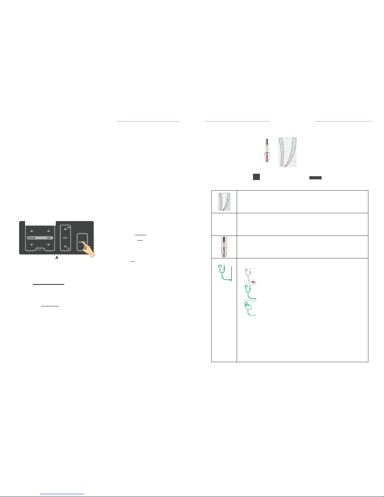
Root apex
area
ijj'
-
0.2
The position of the root apex set by the
dentist.
Full root canal, The
movement
of the file in the root
canal
is
simulated
.
Test wire connection
status:
disconnected
connected
File clip contact connects to lip hook
directly,
it can be used simply to test the test wire is
normal.
r:::7'
NOTE:
It
is recommended to check whether the test wire is
normal
frequently. lfthe
File clip contact connects to lip
hook
directly, but this icon is not
displayed,it indicates a poor
contact.
Then the user can do as
follow:
• Check proper connection of the
cables.
• Clean the File clip
contact.
8
=
'-"' ·
C-SMART-IPro
U11er
Manual
·Press
the MODE key for 2 seconds (A) to enter setting
interface;
·Press
Up or Down key to select AUTO REVERSE (B);
• Press SET key to on/off AUTO REVERSE
function;
·The
change will be saved automatically. Press any key other than SET
and
up or down key to exit the setting, or exit the setting
automatically
after
3
seconds.
Motor option area shows the state of AUTO
REVERSE,
8.3.1.2 Working
area
C·SMART·IPro Uoer
Manual
0.2
Means auto reverse function is
available.
-
Means auto reverse is not
available.
8.3.2.7 LED lighting
function
When LED light is
on,illumination
will be provided during motor
operation,
and if the appropriate delay time is selected, the LED will continue to
provide
delayed
illumination
of the set time after the motor has
stopped.
Set the LED lighting and delay
time:
Ml
f;
•..,.
Fig.16 M1
interface
0
SETUP
A
!'!!.c.
r..o tllnQII••
AI ..
a m-.-
...
•11•
;
!
ght
')t:
!tILIE
EDIHIIytl-.
: :..-.
118
8
:!
tort•refule'W'
...
ltl
0
SETUP
B
English
ON
•
ON •
A
:
ltctdlrr.nnti•1'41UIII•
lA
:!'nR
!':
...... .... _.
;
!!!nlht
')t
!
d•li'JIIIM.
I§Y
!! ri.,..,......,
....
c
Engli11h
ON
•
ON •
3s
• Press the MODE key for 2 seconds (A) to enter setting
interface;
• Press Up or Down key to select LED LIGHTING SWITCH (B);
• Press SET key to on/off LED
lighting;
• Press Up or Down key to select LED DELAY TIME function
(C);
• Press SET key to select different LED delay
times.
• The change will be saved automatically. Press any key other than SET
and
up or down key to exit the setting, or exit the setting
automatically
after
3
seconds.
Page 23
-+
-+
f
C-SMART-
l Pro Uaar
Manual
8-3.1.3
working
1)
Starting
Length
Measurement
&.
CAUTION
C-SMART·lPro Uoer
Manual
•
Connect
the File clip and the lip hook to the test
wire.
• Place the lip hook on the
patient's
lip on the
opposite
side of the tooth to
be
treated.
•
Insert
the file into the root canal and hold the file clip in the metal part of
the
file
(Fig.
17)
• The file
movement
in the root
canal
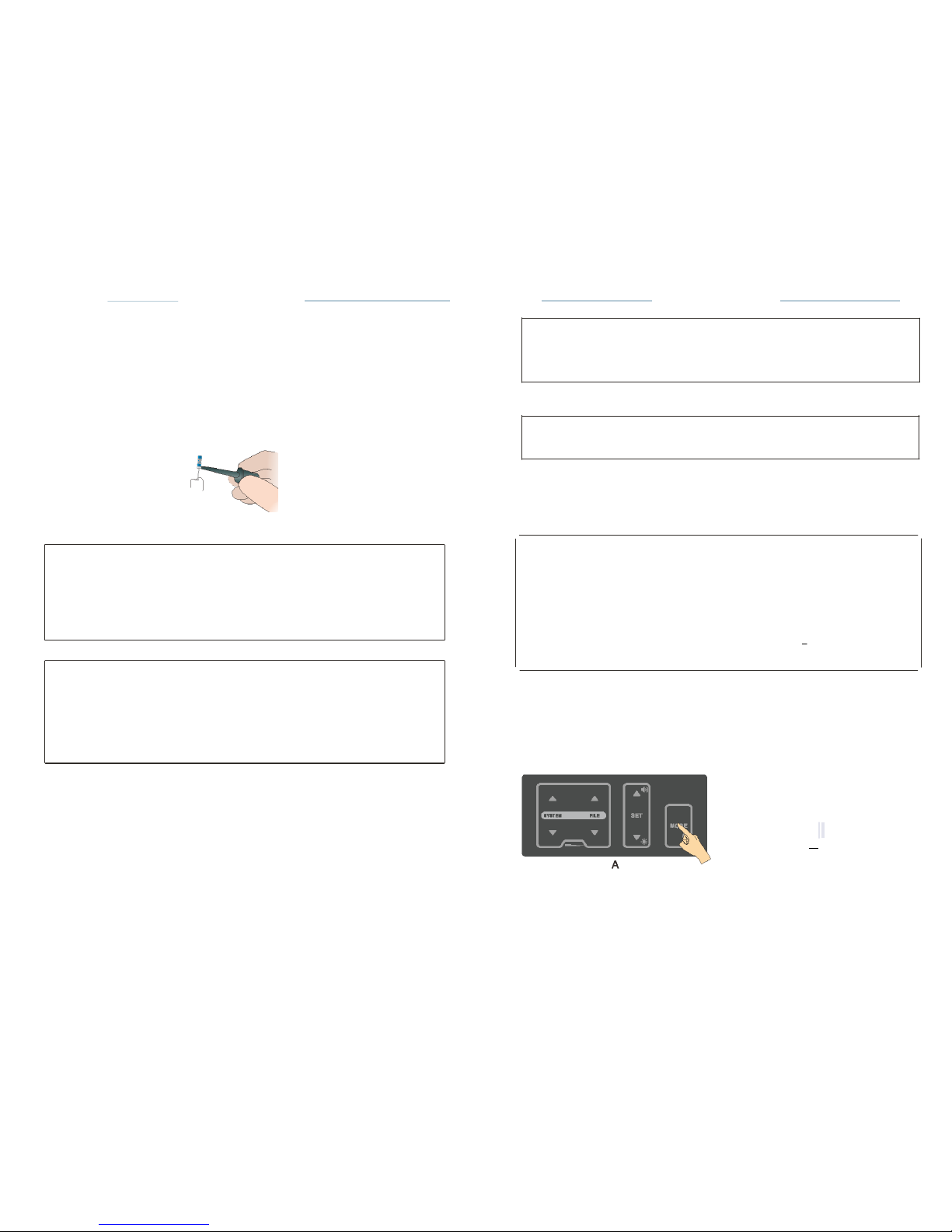
is shown on the left side of the
screen
work area (Fig.
16)
Fig.17
Before
using the motor
handpiece,
verify the
correctness
of the
changed
parameters.
8.3.2.6
Auto
Reverse
r:::J='
NOTE
In
reciprocating motion,the
auto
reverse function
is
disabled.
AUTO
REVERSE
on:
If,
during operation
the load
reaches
the
preset torque limit value,
the
motor
handpiece
will
automatically
rotate in the
reverse
direction.
When the load
is
removed,
the motor
handpiece returns
to
normal forward
rotation automatically.
r:::J='
NOTE
If no
progress
of the file
indicate faulty connection:
•
Check proper
connection
of the test
wire.
•
Clean the File clip
contact.
• Irrigate
the
canal,if
necessary,
and start
again.
&.
CAUTIONS
I
Load
within
the
Torque Limit
Value
I
Forwar
d Rotation!
,T.,
Further Loading
beyond the
preset
Torque Limit
Value
I
Reverse Rotation
I
I
When the load
is
reduced,
The motor
is
automatically restored
I
Forwar
d Rotation!
•
We
recommend
that not to
continue
the
measurement if
the
faulty
connection appears.
•
Go to the CHECK Mode to check the
performance
of the
device
(see
chapter
8.4).
AUTO
REVERSE
off:
If,
during
operation
the load
reaches
the preset torque limit value, the
motor
handpiece
will stop
without reverse
rotation.
If
you want the file to rotate
forward again, press
the ON/OFF key
once.
On/off Auto
Reverse Function:
2)
Measurement
Coronal
and
Medial Area
•
Slowly
insert the
measuring
file into the
canal.
• File
movement
along the
coronaland
medial
section towards
the apex
area
is
represented
on the full root canal image by the file
continuously moving
down
(Fig.
18).
0
SETUP
A
ectdlfl'erelltllng uegu
A
:! fT ;.
AnrwWMmode
F
: !!tgbl
,.-
'!.'!tLb
dll.ytlm..
eg
&:-
8
JIIrlltiiNoMIIMry
MI'III'.f
B
English
.,.
ON
•
ON •
Page 24
C-SMART-
l Pro Uaar Ma nual
C-SMART-lPro Uoar
Manual
Selecting
a File
System
To
choose a different
file
system,
press the SYSTEM .& or T key. The
file
system shown in the
display
is the
selected system.
1)
Continuous Rotary
File
Systems
When a file
system
has been
selected,
the first file of the system
will
automatically
be shown in the
display.
Press the
FILE.,..key
to select the next
file.
Press the FlLE
.t..
key to
select
the
previous
file.
LtcAUTION
Do not use files
designed
for
reciprocating
motion in
continuous
rotation.
2)
Reciprocating
File
Systems
Some files are
designed specifically
for use in
reciprocation, whereby the
device
is
driven
first in a
cutting direction
and then
reverses
to
release the
device. The
angles
of
reciprocation
are
precise
and
specific
to the
design
ofthe device.lf
one of above
mentioned reciprocating
files has been
chosen,
Ml
·<·
•.,
Fig.18 Coronal
and
Medial Area
RootApex Area
•
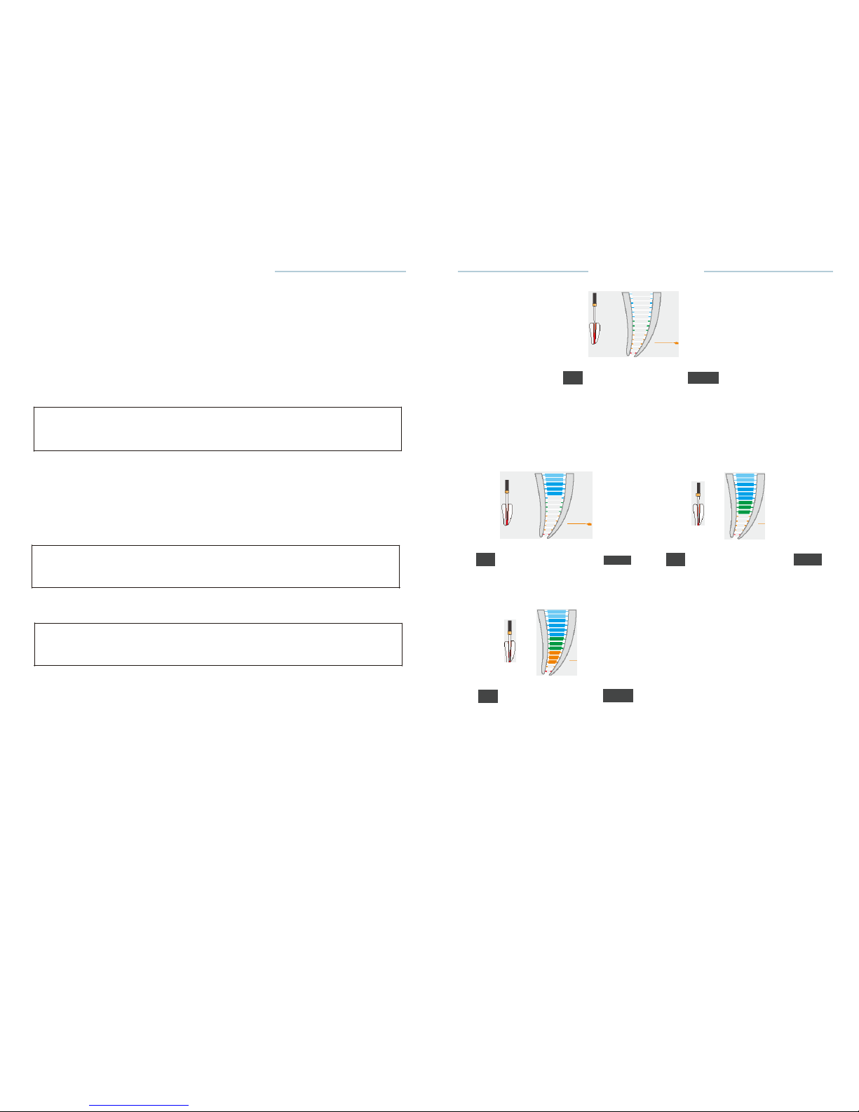
The
movement
of the file is
displayed
on root apex
area.
•In
the root apex area the
indication
dot
indicates
the exact
position and
changes accordingly
from blue to green and then to
yellow
(Fig.
19,Fig. 20).
the
speed
and torque
display
1.2
0.7
LtcAUTION
Do not use files
designed
for
continuous rotation
in
reciprocating
motion.
Ml
<·
•.,
Ml
r:
•.,
Fig.19
ApexArea-Biue
Fig.20
ApexArea-Green
8.3.2.5 Changing
Speed and
Torque
LtcAUTION
While the motor
handpiece
is in
motion,speed
and
torque
can not be
changed
·When
the
desired continuous rotary
file is
selected,
you can
adjust
speed
or
torque value;
·Press
SET keys to select speed or torque to
adjust;
• Press set Up or Down key to
adjust desired
value;
·The
speed
setting
can be
adjusted from150
to 650 rpm. The torque
setting
can be
adjusted
from 0.6 to 5.2
N.cm.
• The
change
will be saved
automatically.
Press any key other than SET
and
up or down key to exit the
setting,
or exit the
setting automatically
after
3
seconds.
·To
return
to
default settings
see
chapter
8.7
Factory Default Parameters.
0.2
Ml
«·
•.,
Fig.21 ApexArea-Yellow
•
File
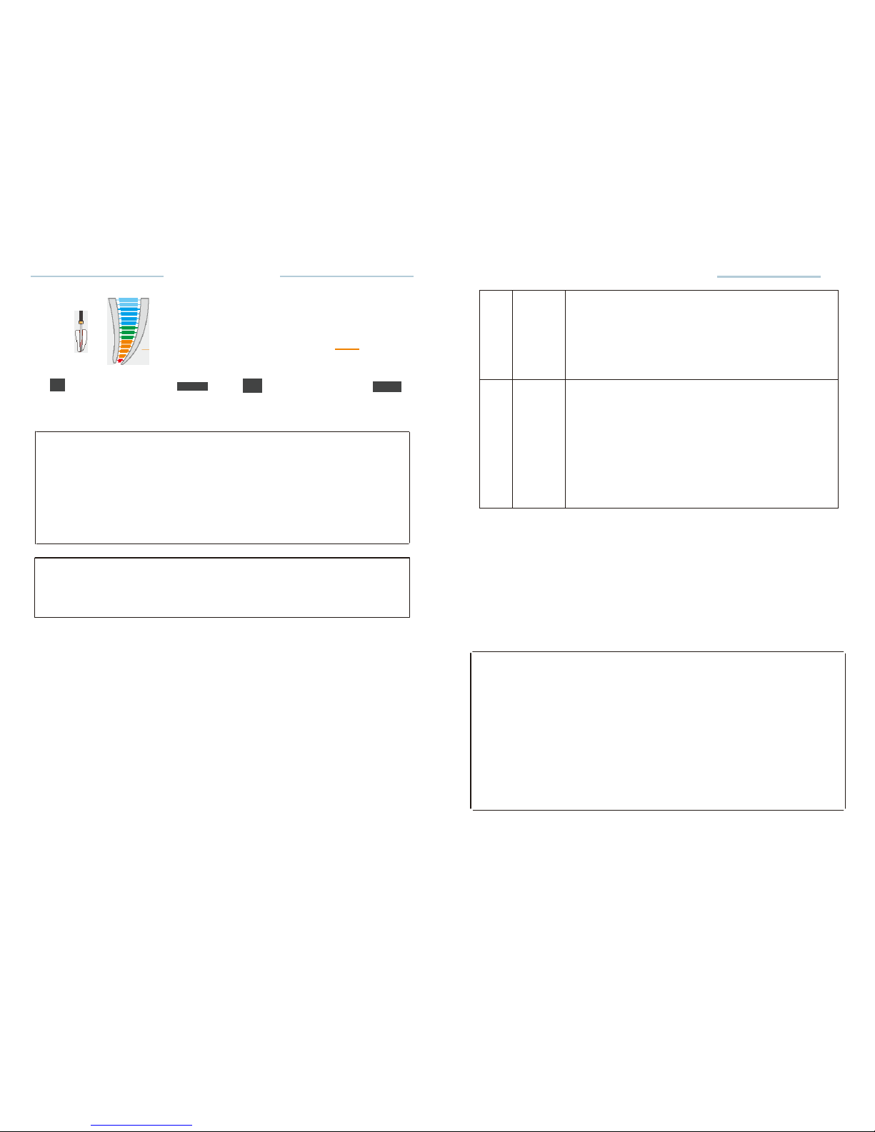
movement
in the Apical Zoom is
accompanied
by audio
signals,which
serve as
additional indication
of the file tip
position.The interval between
the beeps
becomes shorter
the more the file
approaches
the
apex.
•
When the file tip
reaches
the
apical foramen
the
indication
dot is
marked
red and a
constant
sound is
emitted(Fig.
22)
Page 25
7
AUTO
REVERSE
Displays
the AUTO
REVERSE
function
(disabled
for
reciprocating systems).
AUTO
REVERSE on
-
AUTO
REVERSE
off:
See8.3.2.6
Auto
Reverse
8
Motor
and
LED
Lighting
the
Control
unit
E;jl
Means the motor
handpiece
is
connected
to
the
Control unit and LED
lighting function
is
not
available.
Means the motor
handpiece
is
connected
to
the
Control unit , LED
lighting function
is
available
and the delay time is
3S.
See8.3.2.6
LED
lighting function
C·SMART-
l Pro Uaar
Manual
0.0
,
\(_
C-SMART-lPro Uoar
Manual
•
Ml
,f..
•.,
Ml
<· •.,
Fig.22 ApexArea-Red
Fig.23 Beyond
the apex
foramen
-Red dot
•11
The
motor
handpiece
is not
connected
to
(7'
NOTE
The apex
indication
line shows the file tip
position inside
the root
canal:
• Blue
section:
WARNING
section,
close to the apex
area.
• Green to
yellow section:
Root apex
area
• Red
section:
Apex
foramen is
passed
,&caution
As with all
electronic
length
determination
devices, the bars shown in the
root
apex area do not
represent
the
specific
size.
Interruption
of
measurement
During
the
length measurement
the File clip may be
disconnected
from
the
file and
reconnected
at any time
(e.g.when
the file is
changed
to a
larger
size or when the length of
another
root
canal should
be
measured). The
device
detects automatically
that a new length
measurement
cycle
is
initiated.
8.3.2.4 System
and File
Select
File
Library
The device
contains
a file
library,
the preset NiTi
systems please
refer
the
torque card. The
manufacturer reserves
the right to update the file
library
and the
systems contained
in
it.
The device
contains a user-created
system called
PROGRAM.
There are
7
continuous
rotary
files
,&caution
• Follow
the file
manufacturer's instructions
for use of
endodontic
files.
·The
file system shown on the
display
must always match the file in
use.
This
is of the most
importance
in order to
avoid misusing reciprocating files
and
continuous rotary files.
·Torque
and speed values are
subject
to change by the file
manufacturers
without notice. Therefore,
the preset values in the
library
must be
checked
prior to
use.
•
Torque values shown on the
display
are
accurate
and
reliable
only
with
contra
angle
properly maintained
and
lubricated.
Page 26
Symptom
Solution
Excess
liquid
in the pulp
chamber
or
root
canal(rinsing
solution,
blood
or
saliva), creating
wrong
conductive
path and
Incorrect measurements.
Dry the
access cavity
with a
cotton
pelleUair-blower.
Wait until
excess
bleeding
can be
stopped.
Gingival proliferation
can lead to
direct
contact
with the
measuring
file
causing
a short
circuit
and
incorrect
measurements
Isolate the
access
cavity
by:
•
adequate preparation
offilling
•
placing
a
rubber dam
•
electro cauterizing
The
measuring
file
contacting metallic
restorations (crown,
parapulpal post,
amalgam filling)
may cause a
short
circuit
and
incorrect measurements
Enlarge
the
access
cavity
Carefully
and
isolate
with flow
composite.
Widen the
opening
at the top of
the
crown
carefully.
1
SYSTEM
Displays
the selected file
system
2
FILE
Displays
the selected file(s) within the
system.
3
SPEED
Displays
the device
rotation
speed
value
(disabled
for
reciprocating systems).
4
TORQUE
Displays
the torque limit
value
(disabled
for
reciprocating systems).
5
TORQUE
BAR
Displays
the bar graph which shows the degree of
load
applied to the motor while the file is in
continuous
rotation
(disabled for
reciprocating systems).
6
ROTATIONAL
DIRECTION
Displays
the current
rotational
direction
of the
file.
4marks can be
displayed:
Forward
(clockwise) continuous rotation
Reverse(counterclockwise) continuous
rotation
Reciprocating
motion (the forward
angle
more than the reverse
angle)
Reciprocating
motion
<the
forward
angle
less than the reverse
angle)
Change the rotation
direction,
see
8.3.2.8.
C-SMART-IPro
U11er Manual
C-SMART-1
Pro Uoer
Manual
8.3.2 M2
Motor
only (without apex locator)
Press mode key to enter M2 mode. In this mode, has Motor only,
without
apex
locator function.
8.3.2.1 Connection
The
connection method
in this mode is shown in
chapter 7.3.6 ,
Fig.8,Fig.9;
8.3.2.2 Calibration
Calibration
is
recommended
when using a new contra
angle,
the
detailed
calibration
methods,
see
Chapter 8.5.
8.3.2.3 Working area
M2
OA h.
·
(·• ..
Fig.26 M2
interface
8.3.1.4
Tips for
SuccessfulLength measurement
Condition
of
inaccurate measurement
Too fast
movement
or even
jumping
to the apex
directly
is
indicated
for
the
following reasons:
Too slow or
extremely delayed movement
is
indicated
for the
following reasons:
Symptom
Solution
Obliterated
root canal
Impeding the
conductive
path and
preventing
normal
device
functioning.
•
Compared with X-rays, find
possible
clues.
•
Catheterize with ISO 06/ 08 file till
the
working
length.
Retreatment: Blockage
by old
canal
filling
materialresidue, impeding
the
conductive
path and
preventing
normal device functioning.
Take an x-ray to
re-check
and try
to
completely
remove the old root
canal
filling
materialbefore measurement.
Blockage
by
remnants
of a
medicated
substance
(e.g.
calcium hydroxide)
impeding
the
conductive
path
and
preventing
the
normal operation of
the
device.
Remove
the
remnants
Completely
before measurement.
Page 27
Symptom
Solution
Extremely
dry root canal
impeding
the
conductive
path and
preventing
the
normal operation
of the
device.
Rinse root
canal
with
irrigating
solution
such as NaCI or
NaOCI
and dry the
access
cavity with
a
cotton
pellet/
air-blower
.
Symptom
Solution
Exceptionally
large apex
foramen due
to
lesion
or
incomplete formation.
May lead to
shorter measurement
than the
actuallength.
Root
fracture
or
perforation
May lead to
incorrect measurements
C-SMART-I Pro
U11er
Manual
C-SMART-1
Pro Uoer
Manual
•
The
changed
value will be saved
automatically.
Press any key other than
SET
and Up or Down key to exit the
setting,
or exit the
setting automatically
after
3
seconds.
•
When
measuring
the root apex arrow shown as
Fig.25 .
.&..
caution
In some
cases,the
position
of the file can not be
determined accurately.
1.2
Ml
:(·
•.,
Ml
*
•.,
Special condition symptom:
Fig. 24 Set the apex
position
Fig.25
Measurement
process
8.3.1.6 Functional check of the apex
locator
It is
recommended
to check the
performance
of the Apex
Locator
once a week
,
the
detailed
check
methods,
see Chapter
8.4.
Comparison
of
electronic
length determination versus radiography:
X-ray
radiography
shows
two-dimensional projection
of
three-dimensional
root canal
system.
In some cases ,the
radiograph display
length does
not
match the
electron
assay
length.
In the case of a
lateral
canal
curvature
,the x-ray may show a
shorter
working length
than the
device's measured
value.
Electronic length measured
using the
instrument
is
usually
more
accurate
more
accurate
than the
radiographic
length on the
X-ray.
8.3.1.5
Set the DR'S CHOICE apex
position:
This
feature enables
to mark an
individualpredetermined reference
position
at the
required distance
from the apex. This
variable apical
arrow can be
set
between
the green bar and the
yellow bar.
When DR'S CHOICE
apical
arrow is set, clear visual and audio
indication
is
given
that the file tip has
reached
this
pre-selected
position.
To set the DR'S CHOICE apex
position,
follow the next
steps:
• Press the SET key, the apex setting icon
becomes adjustable
state,
(Fig.24)
·Press
the Up or Down key to
adjust
the apex
position.
 Loading...