

Page 1

READ THIS MANUAL BEFORE OPERATING MACHINE
DEATH, PERSONAL INJURY AND/OR PROPERTY DAMAGE MAY OCCUR UNLESS INSTRUCTIONS IN THIS MANUAL ARE FOLLOWED
NOTE: Bring this Manual when Service & or Warranty work is required.
RIDE-ON MOWER
OWNER/OPERATORS MANUAL
Model A16915G
Hydrostatic Drive
CS45H20B35-14.9Kw (20hp) Briggs & Stratton 890mm (35”) Cut
CS45H20B42-14.9Kw (20hp) Briggs & Stratton 1055mm (42”) Cut
Page 2

1 February 2016 Page 2
Owners Manual for Model A16915G Hydro Drive
ISSUED BY:
ISSUED TO:
OWNERS INFORMATION
MACHINE CODE NO:__________________________
SERIAL NO:_______________________
Located on label inside transmission housing
B&S ENGINE MODEL NO:______________TYPE____________ CODE_______________
DATE OF PURCHASE:__________________________________
OWNERS NAME:
ADDRESS:
TOWN/CITY:
STATE:
AUTHORISED DEALER/
DISTRIBUTOR:
ADDRESS:
TOWN/CITY:
STATE:
PRE DELIVERY CHECK LIST
Check parts Assemble Service Instruction
ALWAYS KEEP THIS MANUAL IN A SAFE PLACE.
Page 3

1 February 2016 Page 3
Owners Manual for Model A16915G Hydro Drive
Read, understand, & follow all instructions in
the Owner/Operators manual.
Know the controls and how to stop the
engine quickly in an emergency.
Allow only responsible adults, who are
familiar with the instructions in this manual,
to operate the machine.
Clear the area to be mowed of loose objects
such as sticks, stones, bones, wire, toys,
debris, etc., which could be picked up and
thrown by the blades.
DO NOT mow whilst people, especially
children, or pets are in the mowing area.
DO NOT mow either direction on slopes
beyond 15 degrees (1 in 3.75).
Exercise extreme caution on slopes.
Reduce speed on slopes and in sharp turns to
prevent overturning or loss of control.
Start or stop slowly when on slopes.
Mow up and down slopes, not across the
slope.
Stay alert for holes or bumps in the terrain
and other hidden hazards.
Watch out for traffic when crossing or
operating the mower near roadways.
Stop the blades rotating before crossing
surfaces other than grass.
When using attachments, never direct
discharge of material toward bystanders nor
allow anyone near the machine while it is in
operation.
Before leaving the operators position-
a] Disengage all clutches and secure cutting
units;
b] Return drive pedal to neutral position and
set the parking brake;
c] Stop the engine and remove the key.
Disengage drive to attachments and stop
enginea] Before refueling;
b] Before checking, cleaning or working on
the mower;
c] After striking a foreign object (check the
mower for damage and make repairs before
restarting and operating the equipment);
d] If machine starts to vibrate abnormally
(check immediately).
Disengage drive to attachments when
transporting or not in use.
A mower operator should be in good physical
and mental health and not under the
influence of alcohol or any drug which might
impair vision, co-ordination or judgment.
Never mow while barefoot or wearing open
sandals or thongs. Wear long trousers and
heavy shoes.
It is advisable to wear suitable eye protection
when operating a mower.
Mow only in daylight or good artificial light.
Before using, always visually inspect to see
that blades, bolts and cutter assembly are not
worn or damaged. Replace worn or damaged
blades and bolts in sets to preserve balance.
Check all nuts, bolts, and screws often;
always be sure the mower is in safe
operating condition.
Keep safety devices (guards and switches) in
place and in working order.
Never use the mower unless the guards
provided by the manufacturer, are in
position.
Ensure any replacement parts used comply
with the original manufacture’s
recommendations and specifications.
Replace worn or faulty silencers.
Keep machine free of grass, leaves or other
debris, excessive oil, grease, or spilt fuel.
These can be a fire hazard.
Refuel outdoors only. Do not smoke while
fueling engine. Never remove the cap of the
fuel tank or add petrol while the engine is
running or the engine is hot. Remove fuel cap
slowly to relieve any tank pressure. If fuel is
spilled, do not attempt to start the engine but
move machine away from the area of the spill
and avoid creating any source of ignition until
fuel vapors have dissipated.
Check for fuel leaks while refueling, before
and while using the mower. If a fuel leak is
found, do not start or run the engine until the
fuel leak is fixed and spilled fuel is wiped
away.
Do not operate engine in a confined space
where exhaust fumes (carbon monoxide) can
collect.
Always mount the mower from the left or the
opposite side to the discharge chute.
Start the engine carefully with the cutting
means disengaged.
Do not over-speed the engine or alter
governor settings. Excessive speed is
dangerous and shortens mower life.
Stop the engine whenever you leave the
mower, even for a moment.
Store the mower in a well-ventilated room
away from naked flames such as may be
found in hot water heaters.
Do not lend or sell the mower, without the
owners/operators Manual.
SAFETY INSTRUCTIONS
Page 4

1 February 2016 Page 4
Owners Manual for Model A16915G Hydro Drive
INTRODUCTION
THANK YOU, for purchasing a COX Hydrostatic Drive, STOCKMAN 4500 Ride-on Mower.
Proudly Manufactured by Cox Industries (Australia) Pty. Ltd..
GENERAL SAFETY INSTRUCTIONS
READ THIS MANUAL carefully to
learn how to operate safely and
maintain your Ride-on Mower
effectively.
Failure to follow Safety, Operating
or Maintenance instructions in this
manual could result in
Death , P e rsonal I n ju ry or
Equipment Damage.
THIS MANUAL IS PART OF
YOUR RIDE-ON MOWER and
should be supplied with this Rideon Mower if you lend or sell this
Ride-on Mower. This should also
apply to the Engine Owners
Manual.
CONVENTIONS
Measurements in this manual are
given in metric units unless
otherwise stated.
Right-hand and Left- hand, are
determined by facing the direction
of forward travel.
Direction of rotation is determined
by looking into the components in
motion parallel to the axis of
rotation.
W R I T E P R O D U C T
IDENTIFICATION NUMBERS in
the Owners Information Section of
this manual. Accurately recording
these numbers will assist your Cox
Dealer when ordering spare parts
or help in tracing the Ride-on
Mower if it should be stolen. Store
this manual in a secure place
remote from the Ride-on Mower.
ENSURE YOU UNDERSTAND
THE WARRANTY POLICY with
regard to the responsibilities of
op eratio n , mai n t enanc e an d
ownership of this COX STOCMAN
Ride-on Mower.
THE INTENDED USE OF THIS
RIDE-ON MOWER is for
customary mowing of Landscaped
Parks, Gardens, Grounds, Sporting
Fields, Road Verges, Golf Course
Fairways, Orchards, Plantations,
and Vineyards.
Strict adherence to the conditions
of Operation, Maintenance, Service
& Repair as specified by the
manufacturer constitute essential
elements for The Intended Use.
Use in any other way not
specifically approved directly in
righting by the manufacturer is
considered as contrary to the
intended use and will increase the
risk of personal injury or property
da m ag e a n d i s t h er e f o re
considered as misuse for which the
m a n u f a c t u r e r a c c e p t s n o
responsibility as these increased
risks must be accepted solely by
the user.
Do Not Modify the Machine
without direct specific approval by
the manufacturer as modification is
co n sider e d co n trary to th e
intended use and will increase the
risk of personal injury or property
da m ag e a n d i s t h er e f o re
considered as misuse for which the
m a n u f a c t u r e r a c c e p t s n o
responsibility as these increased
risks must be accepted solely by
the user.
OPERATION, MAINTENANCE,
SERVICE AND REPAIR of this
Rid e - on M ower s h ould b e
performed only by persons familiar
wi th its cha r acte rist ics an d
acquainted with the relevant
Safety, Operating and maintenance
instructions in this manual, as well
as a l l r el e v a nt St at u t o ry
Regulations in force at the place
and time.
When your Ride-on Mower needs
service or repair please remember
your Cox Dealer is an industry
trained professional who is
supported by the personnel of the
Sales and Marketing, Engineering,
Production, Procurement, Parts
Distribution, & Service Sections of
the Manufacturer and is dedicated
to your satisfaction.
THE INFORMATION INCLUDED
IN TH I S M AN U AL w a s
considered correct at the time of
app ro va l f o r p r i n t i n g . C o x
Industries (Australia) Pty Ltd
reserves the right to change
specifications or designs without
notice or obligation.
Training
Read, understand and follow all
instructions in the Ride-on Mower and
Engine Owner’s/Operator’s Manual as
well as on Machine Safety Signs.
Keep up to date with and follow
all relevant statuary regulations in
force at the place and time with
regard to ownership, transport,
operation, maintenance, service, and
repair, disposal or sale of this
machine.
Know the controls and the
proper use of the Equipment as
well as how to stop the Mowing
Attachment, Machine Travel, and
the Engine in an emergency.
All operators or users should
seek and obtain professional
and practical instruction.
Such instruction should emphasize:
The need for concentration when
working with ride-on machines.
Control of a ride-on machine
sliding on a slope will not be
regained by application of the
brake.
The main reasons for loss of
control are:
i) Insufficient wheel grip;
ii) Being driven to fast;
iii) Inadequate braking;
iv) The type of machine is
unsuitable for the task;
v) Lack of awareness of the
effect of ground conditions,
especially slopes;
vi) Incorrect hitching and load
distribution.
Never allow children or people
unfamiliar with these instructions
to operate the Ride-on Mower.
Never carry passengers.
Never mow while people,
especially children, or unrestrained
animals are nearby.
Keep in mind that the operator or
user is responsible for accidents or
hazards occurring to other people
or their property caused by this
machine.
Page 5

1 February 2016 Page 5
Owners Manual for Model A16915G Hydro Drive
Preparation
While operating, always wear
substantial footwear (not open
sandals) and long trousers.
Thoroughly inspect the area
where the equipment is to be used
and remove all objects which can
be thrown by the machine.
WARNING – Petrol is highly
flammable:
i) Store fuel in contain ers
specifically designed for this
purpose;
ii) Refuel outdoors only;
iii) Do not smoke while refuelling;
iv) Add fuel before starting the
engine;
v) Never remove the cap of the
fuel tank or add petrol while
the engine is running or when
the engine is hot;
vi) If petrol is spilled, do not
attempt to start the engine but
move the machine away from
the area of spillage and avoid
creating any source of ignition
until petrol vapours have
dissipated;
vii) Replace all fuel tank caps and
container caps securely.
Replace faulty Mufflers.
Before using, always visually
inspect to see that the cutter
assembly, blades, and blade bolts
are not worn or damaged.
Replace worn or damaged
blades and bolts in sets to
preserve balance.
Take care rotating one blade
by hand as this can cause other
blades to rotate.
Operation
Do not operate the engine in a
confined space where dangerous
carbon monoxide fumes can
collect.
Operate the machine only in
daylight or in good artificial light.
Before attempting to start the
engine, disengage Power take off
Clutch and depress clutch/brake
ped a l t o e n s u re d r i ve is
disengaged to the transmission.
Do not use on slopes of more
than 15 degrees (1 in 3.75 or
27%).
There is no such thing as a
safe slope.
Travel on grass slopes requires
particular care.
To guard against overturning:
i) Do not stop or start suddenly
when going up or downhill;
ii) Engage hyd rostatic driv e
slowly;
iii) Always keep hydrostatic drive
operating, especially when
travelling downhill;
iv) Machine speeds should be
kept low on slopes and during
tight turns;
v) Stay alert for humps and
hollows and other hidden
hazards;
vi) Never mow across the face of
the slope.
Use care when pulling loads or
using heavy equipment:
i) Use only approved hitch
points;
ii) Limit loads to those you can
safely control;
iii) Do not turn sharply;
iv) Use care when reversing;
Watch out for traffic when
crossing or near roadways.
Stop the blades rotating before
crossing surfaces other than grass.
When using the mowing
attac h m e nt, ne v e r d irect
discharge of material towards
bystanders nor allow anyone else
near the machine while it is
operating.
Never operate the machine
with defective guards, or
without all safety devices in place
and operating correctly.
Do not change the engine
governor settings or over speed
the engine as excessive engine
speed can increase the risk of
personal injury.
Before leaving the operators
position:
i) Disengage the power take off
clutch:
ii) Set the parking brake in the
locked position.
D i s e n g a g e d r i v e t o
attachments when transporting,
emptying the catcher, or not in
use.
D i s e n g a g e d r i v e t o
attachments and stop engine
before refuelling.
D i s e n g a g e d r i v e t o
attachments, stop engine, and
remove the ignition key:
i) Before leaving the machine
unattended;
ii) Before clearing blockages or
unclogging the chute;
iii) After striking a foreign object.
(Inspect the machine for
damage and make repairs
before restarting or operating
the damaged equipment);
iv) If the machine starts to vibrate
a b n o r m a l l y . ( C h e c k
immediately).
D i s e n g a g e d r i v e t o
attachments, stop engine,
remove the ignition key, and
disconnect the spark plug
wires and battery positive lead
before working on, maintaining, or
servicing the machine.
S e c u r e t h e m o w i n g
attachment in the full up
position:
i) Before clearing blockages or
unclogging the chute;
ii) Before replacing the blades, or
adjusting the tension of the
blade bolts;
iii) Before placing any tools or any
part of your person under the
mowing attachment.
Turn the fuel off using the fuel
shut off valve at the conclusion
of operation.
Maintenance and
Storage
Keep all nuts, bolts and screws
tight to ensure the equipment is
in safe working order.
Replace worn or damaged
parts for safety.
Reduce the fire hazard, by
keeping the engine, muffler,
hydrostatic transaxle, battery
compartment, and petrol storage
area clear of grass, leaves, or
excessive oil and grease.
Also ensure the mowing
attachment drive belt can not
come into contact with grass,
sticks, and leaves built up on the
top surface of the mowing
attachment.
If the fuel tank has to be
drained this should be done out
outdoors.
Never store the machine with
petrol in the tank inside a
building where fumes can reach an
open flame or spark.
Allow the engine to cool before
storing the Ride-on Mower in any
enclosure.
When the machine is to be
pa r ke d , stored or l e f t
unattended raise the mowing
attachment and secure it in the full
up position.
GENERAL SAFETY INSTRUCTIONS CONT.
Page 6

1 February 2016 Page 6
Owners Manual for Model A16915G Hydro Drive
PRE-DELIVERY INSTRUCTIONS
UNPACKING INSTRUCTIONS
Unpacking Instructions
Inspect the shipping crate and contents for
damage.
Position the shipping crate on a firm flat
level surface with at least 3 meters
distance from any obstruction to the end of
the crate adjacent to the front of the
tractor.
! Caution you can be seriously
injured by the metal strapping
which has sharp edges and can
spring out when cut. Wear gloves
when handling metal strapping.
! Caution you can be seriously
injured by sharp nails protruding
from the shipping crate.
Cut and remove the straps restraining the
tractor to the ends of the shipping crate.
Remove the end of the shipping crate
adjacent to front of the tractor.
Remove the plastic sheet covering the
tractor.
Unlock the park brake knob by depressing
the clutch/brake pedal (the pedal on the
left side of the tractor). Pull the transaxle
transmission pump bypass lever fully
forward to bypass the transmission pump
and allow the tractor to be pulled with less
effort.
Pull the tractor from the shipping crate.
Depress the brake pedal while lifting up on
the park brake knob. Once the park brake
knob is raised release the brake pedal and
then the park brake knob.
The Park brake should now be locked on.
Push the transaxle transmission pump
bypass lever fully rearward to engage the
transmission pump and allow the tractor to
be driven.
Remove the steering wheel, seat sub-assy,
& other loose components from the
packaging.
Dispose of all packaging material
responsibly.
Do not leave the plastic sheet
unrestrained, it can blow away to
become a safety hazard.
INTRODUCTION:
The purpose of this procedure is to
ensu re the d eal er/ d ist ributor has
assembled & made the necessary
checks, & adjustments, before the
mower is operational, and instructed the
owner in its safe operation &
maintenance. This procedure begins
upon receiving the crated mower and is
finalised once the mower has been
either sold or leaves the dealer/
distributors premises. This is the
minimum amount of work required,
however it should not be limited to only
the areas detailed in this procedure.
RESPONSIBILITY:
It is the responsibility of the dealer/
distributors to ensure that before a
mower is delivered to a customer, it is in
perfect operational condition.
PROCEDURE:
CHECK COMPONENTS SUPPLIED IN
SEAT PROTECTION BAG
Engine owners manual
Owner/Operator manual
Ignition keys (AM015)
Steering wheel (SW14H)
Roll Pin (DP10)
Spring pull hook (13127)
Tommy bar (AM007)
Set Screws M8X20 (SH0820M) x 2
Nuts M8 Nyloc (NM8NT) x 2
Seat Springs x 2 (A163060)
Spring Caps x 2 (A160231)
Washer (W05M202) x 2
Warranty Card
Pre-delivery Instruction Sheet
ASSEMBLY:
TOOLS & EQUIPMENT REQUIRED:
Socket set containing 13mm a/f socket &
extension 75mm (3”) or longer. Spanner
13mm a/f. Hammer & 6mm or 1/4” pin
punch.
Refer pictorial procedure provided.
STEERING WHEEL
To attach the steering wheel, align the
hole in the steering wheel boss to the
hole in the steering shaft and use a
hammer and suitable punch to drive the
DP10 roll pin through the steering
wheel and shaft. Ensure that the pin is
situated centrally in the steering wheel
boss and that the steering is free to
turn.
Press the steering wheel center cover
into place using hand pressure only.
HOURMETER
Connect the black negative wire to the
terminal supplied at the back of the
hourmeter.
SEAT MOUNT & SEAT SPRINGS
Install the two seat springs using the
screws, washers, nuts, to the seat slide
frame, and tighten the screws, washers,
and nuts. Install the Seat & Mounting to
the seat slide frame using the Screws
and Nuts. Attach seat switch wiring to
seat switch.
CHECK TYRE PRESSURES & FLUID
LEVELS:
TYRES
Before operation ensure that tyre
pressures are equal on both sides.
Uneven pressure can give an uneven
finish when mowing and may cause
damage to tyres and/or tubes.
The recommended pressure is:
Front 170kPa (24 P.S.I.). Rear 100kPa (15 P.S.I.)
BATTERY
This machine is fitted with a maintenance
free battery.
ENGINE OIL
Before operation ensure that engine oil
level is to the full mark on the dipstick.
(Refer engine owners manual for
procedure & if some oil needs to be
added refer Engine owners Manual for
Correct Grade).
FUEL
Ensure the fuel tap at the bottom left
front side of fuel tank is turned to the on
position before attempting to start
engine. (Use unleaded fuel only).
CHECK OPERATION OF SAFETY
SWITCHES:
STARTING
Clutch/Brake switch
With PTO (power take off) switch in
disengaged position (down/off) attempt to
start engine without the clutch/brake pedal
depressed. Engine should not start.
PTO switch
Sit on seat with the clutch/brake pedal fully
depressed and PTO switch engaged (On),
attempt to start engine. Engine should
not start.
Key Switch
With PTO switch in down (disengaged/
off) position & clutch/brake pedal fully
depressed turn key switch to start
position. Engine should start.
STOPPING
Seat switch
Sit on seat and start engine, engage cutter,
(manual or electric control) and lift weight
from seat.
Engine should stop.
Clutch/Brake switch
Sit on seat and start engine depress clutch/
brake pedal and apply park brake, lift
weight from sear.
Engine should continue to run.
Sit on seat with engine running and park
brake off , clutch/brake pedal not
depressed and lift weight from seat.
Engine should stop.
Key Switch
Sit on seat and start engine, turn
key switch to stop position.
Engine should stop.
Page 7
1 February 2016 Page 7
Owners Manual for Model A16915G Hydro Drive
ITEM PART NUMBER DESCRIPTION QTY
1 A163060 Spring, Compression, Conical, Seat, Heavy 2
2
Sub-Assy, Seat, Sman 4500 1
3 DP10 Pin, Roll, Spring,1/4"X1-3/4",Znpl 1
4 NM8NT Nut, Hex, Nyloc, Thin, M 8,Pc6,Znpl 4
5 SH0820M Screw, Hex, M 8x 20,Pc8.8,Znpl 2
6 SH0825M Screw, Hex, M 8x 25,Pc8.8,Znpl 2
7 SW14H Wheel, Steering,14",02hub+Cover 1
8 W051218 Washer, Flat, Bright,5/16"X3/4"X18g,Znpl 4
9 W05M202 Washer, Flat, Bright,5/16"X3/4"X14g 2
A168231 Cap, Spring, Seat 2
PRE-DELIVERY PARTS EXPLODED VIEW
Page 8

1 February 2016 Page 8
Owners Manual for Model A16915G Hydro Drive
IMPORTANT
RECOMMENDED FUEL
Unleaded fuel is recommended by
all manufacturers of engines
fitted to Cox products.
SAFETY SWITCHES
Before operating machine, ensure
that all safety switches are
operating correctly. Do not
operate machine with faulty,
missing or damaged safety
switches.
BLADE WARNING
Do not use mowing attachment
with broken or bent blades,
damaged or worn bolts and nuts
or damaged cutter disc, otherwise
damage and premature wear will
result from vibration. Replace
blades, bolts and nuts only in
pairs to maintain correct balance.
Recommended blade nut torque
is 36-40Nm. Do not over tighten.
Keep both feet and hands
clear of the mowing
attachment at all times
while attempting to start
or operate the machine.
WARNING
DO NOT OPERATE
WITHOUT MOWING
ATTACHMENT
DEFLECTOR FITTED &
DOWN.
Reference to left or right hand
side of machine is determined by
sitting in the operating position
on the machine.
Safety footwear is recommended
when operating machine.
Reference to left or right hand
side of machine is determined by
sitting in the operating position
on the machine.
Mount and dismount only from
left hand side of machine.
Ensure machine has clutch/brake
pedal fully depressed or parking
brake engaged when attempting
to start engine.
Never allow engine revs to
exceed more than 3600 RPM.
The Instruments,
the Controls and
their functions are
as follows;
Key Switch-
Used to start and stop engine. Insert
key, turn key all the way right to
start (3rd) position to start engine.
When key is released from start
(3rd) position it will return to on |
(2nd) position. Turn key all the way
left to off O (1st) position to stop
engine. Remove key from off O (1st)
position to lock ignition switch.
PTO Switch-
Used to activate the electromagnetic
clutch/brake to start (engage) and
stop (disengage and brake) mowing
attachment blades and allow starting
of engine with mowing attachment
blades disengaged from engine.
With engine running at fast speed
pull KNOB up to (ON) position to
start (engage) mowing attachment
blades. Push knob down to (OFF)
position to stop (disengage and
brake) mowing attachment blades.
Seat Switch-
Used to stop engine if operator is
not on the seat (switch not
depressed) & cutter engagement
PTO switch is engaged (on) or the
park brake switch is not depressed
(park brake not locked on).
Clutch/Brake Pedal & Park
Brake Switch-
Used to allow starting of the engine
when depressed.
Used to stop engine when not
depressed and seat switch is not
depressed.
Hourmeter-
Used to indicate the number of
hours the engine has operated.
Note:- Ignition switch must be in the
on position for the hourmeter to
display hours.
Engine Speed/Choke
Control Lever-
Used to regulate engine speed and
cutter speed also to engage/
regulate/disengage the engine
choke to assist in starting a cold
engine. Push LEVER fully forward to
engage the engine choke fully.
Pull LEVER back so front edge of
LEVER is in line with the fast (rabbit)
symbol on dash decal to disengage
choke fully.
Pull LEVER back for slow engine and
cutter speed and push LEVER
forward to fast symbol on dash
decal for fast engine and cutter
speed.
Clutch/Brake Pedal-
Used to disengage drive to the
transaxle and apply the brake to
slow or stop machine travel in
forward or reverse direction. Used to
allow engagement of park brake in
locked (on) position. Used to allow
starting of engine. Used to release
park brake from locked (on)
position.
Depress PEDAL to apply brake.
Depress PEDAL to allow raising of
park brake knob to locked (on)
position. Depress PEDAL to allow
starting of engine. Depress PEDAL to
release park brake from locked (on)
position.
Park Brake Knob-
Used to lift the park brake rod and
engage with the clutch/brake
linkage to secure the brake into the
locked (on) position.
Used to allow starting of the engine
if the mowing attachment is stoped
(PTO. clutch/brake knob is pushed
down) without the operator
depressing clutch/brake pedal or
being on the operators seat.
Used to allow the operator to leave
the operating position with the
engine running if the park brake is in
the locked (on) position and the
mowing attachment is also stoped
(PTO. clutch/brake knob is pushed
down).
Depress brake pedal fully, then lift
the park brake KNOB into the locked
(on) position and release the brake
pedal, leaving the KNOB in the
locked (on) position. Depress the
clutch/brake pedal to release the
park brake and let it return to the off
position.
!
OPERATING INSTRUCTIONS
Page 9

1 February 2016 Page 9
Owners Manual for Model A16915G Hydro Drive
Seat Adjustment Lever-
Used to allow adjustment of the seat
backwards or forwards to give the
most comfortable operating position.
Pull the LEVER left to unlock the
seat slide mechanism, and move
seat backwards or forwards until
most comfortable operating position
is reached, release LEVER and
attempt to move the seat
backwards or forwards slightly to
allow the LEVER to return to the
fully right position and to ensure the
seat is locked in position.
Drive Pedal-
Used to control an infinitely variable
ground speed between zero and
maximum in forward or reverse.
Also to select neutral. With engine
running and clutch/brake pedal
released push down on front of
drive pedal to travel forward, push
down on back of drive pedal to
travel in reverse. When pressure is
released from front or back of pedal
it will return to neutral position.
M o w i n g At ta c h m e n t
Cutting Height Adjustment
Lever-
Used to change the mowing
attachment cutting height. To alter
cutting height, lift lever slightly and
depress button, move lever up to
raise or down to lower the mowing
attachment cut height, stop at
desired cutting height and release
button to lock at 1 of 10 height
positions.
NOTE– Do Not mow in any
direction on slopes beyond
15 degrees (1 in 3.75).
Transmission Pump By-Pass
Lever-
Used to disengage the transmission
to allow the mower to be pushed
easily. Located at the front of the
transmission and near the middle of
the chassis. Move lever to back for
normal operation or move lever
forward for free wheel.
Fuel Tap Knob-
Used to shut off the fuel line to stop
fuel flow to the engine when the
tractor is transported or not in
operation to reduce the likelihood of
fuel leakage. Turn the KNOB
clockwise ¼ of a turn from the on
position to the off position to shut
off the fuel line to stop fuel flowing
to the engine. Turn KNOB
anticlockwise ¼ of a turn from the
off position to the on position to
allow fuel to flow to the engine.
Oil Level Dipstick-
Used to indicate oil level in engine
when engine is not running. (Refer
to engine owners manual for
instructions on checking engine oil
level)
TO OPERATE
B E F O R E S T A R T I N G /
STOPPING:
See Engine Maintenance/
Instruction Sheet.
Check engine oil level, check fuel
level, turn fuel tap on.
STARTING ENGINE
Cold Engine: To start engine, place
speed control lever into choke
position, ensure PTO switch is in the
“off” position, park brake locked or
clutch/brake pedal fully depressed,
insert key in key switch, turn key all
the way right to start (3rd) position,
release key when engine has
started.
Note: More than 15 seconds of
continuous cranking can damage
the starter motor. Short starting
cycles give best starter motor life.
Allow starter motor to cool for 2
minutes before attempting to restart
engine. After engine starts gradually
move speed control lever, out of
choke position to obtain desired
engine speed.
Hot engine:
To start engine, place speed control
slightly past slow position, ensure
PTO switch is in the “off” position,
park brake locked or clutch/brake
pedal fully depressed, insert key in
key switch, turn key all the way right
to start (3rd) position, release key
when engine has started. Move
speed control lever to obtain desired
engine speed.
STOPPING ENGINE
When stopping engine, ensure PTO
switch is in the off position, return
speed control to fast position, lock
park brake, turn key switch to the
“off” (1st) position.
DRIVING
To Travel Machine Forward Or
Reverse-
With engine running set speed
control lever to obtain desired
engine speed, ¾ to full speed for
the best mowing finish and for
engine and transmission cooling.
Release park brake, let the clutch/
brake pedal all the way out, apply
downward pressure on front of drive
pedal to travel forward, or apply
downward pressure on back of drive
pedal to travel in reverse. It is not
necessary to apply foot brake before
changing from forward to reverse or
reverse to forward. The amount of
pedal travel is used to control the
ground speed, small downward
travel will give a slow ground speed,
full downward travel will give a fast
ground speed.
NOTE Use slower ground
speed for traveling up and
down slopes, turning, or
mowing heavy growth.
Take care when reversing,
always look in the direction
of intended travel before
changing direction.
To Stop Machine Travel-
Apply clutch/brake pedal fully, this
will disconnect the drive belt to the
transmission before the brake is
activated.
OPERATING INSTRUCTIONS CONT.
Page 10

1 February 2016 Page 10
Owners Manual for Model A16915G Hydro Drive
MAINTENANCE INSTRUCTIONS
It is the owner’s responsibility to ensure
that all-periodical checks, necessary
adjustments, services and repairs are
carried out. Failure to do so may result in
death, personal injury and/or property
damage.
Before attempting any maintenance, stop engine,
ensure mowing attachment blades have stopped
rotating, disconnect spark plug lead from spark plug
and ground it, disconnect battery at negative
terminal, to prevent accidental starting.
Position machine on a flat level surface for
maintenance.
Never alter factory setting of maximum engine
R.P.M (3600).
Reference to the left or right side of the machine is
determined by sitting in the operating position.
IMPORTANT: If operating in adverse conditions
such as those mentioned below, change engine oil,
air filter, lubrication and adjustments should be
carried out at less time intervals than specified in
this booklets maintenance schedule. Ensure
machine has park brake engaged when attempting
to start engine.
a. Mowing in hot or wet conditions.
b. Mowing in rough or dusty conditions.
c. Mowing hilly areas or continuous heavy
load conditions.
CHECK & ADJUST ENGINE OIL LEVEL - Refer
to engine owners manual for correct method to
check & adjust engine oil level.
CHANGE ENGINE OIL & OIL FILTER
Refer to engine owner’s manual for correct method
to change engine oil & oil filter.
CHECK ENGINE AIR CLEANER & FOAM PRECLEANER-
Refer to engine owners manual for correct method
to check and service engine air cleaner & foam precleaner.
CHECK BONNET SIDE MESH If mesh is more than one quarter blocked by debris
clean mesh. Wipe mesh with hand, rag or brush to
remove debris from mesh.
CHECK ENGINE ROTATING SCREEN Refer to
engine owners manual for correct method to check
and clean engine rotating screen /debris guard.
LUBRICATION OF MACHINE- Lubrication of
machine must be carried out every 25 hours of
operation or once a month, whichever occurs first.
Lubricate at less time intervals when operated
under adverse conditions.
OILING: A few drops of oil should be placed at
the following points: Steering rod ends, mower
suspension link rod end, height adjustment
mechanism.
CHAIN: Use only chain lube for lubrication of the
steering chain.
GREASE POINTS: Grease nipples are located on
top of the front wheel stub axles.
GREASE STUB AXLES:
Clean grease nipple, use grease gun and generalpurpose grease to force old grease from top and
bottom of front axle bushes. Iif grease is not
released from bottom of bush jack up front of
machine and try again .
ENGINE TO TRANSMISSION VEE BELT
ADJUSTMENT- Tension is automatically
adjusted by the belt tensioning springs.
ENGINE TO CUTTER VEE B ELT
ADJUSTMENT- Tension is automatically
adjusted by the belt tensioning springs.
TO ADJUST STEERING CHAIN- Adjust chain
by loosening the two bolts which hold the
steering idler shaft mounting bracket in
position, slide rearwards to tension chain then
retighten bolts.
CHECK CLUTCH OPERATION – With pedal in up
position check for 3-4mm play in the disengage
linkage slot and the disengagement arm pin (adjust
after removing ‘R’ pin and washer) and turning
linkage in or out to achieve correct play (replace ‘R’
pin and washer).
CHECK BRAKE OPERATION –
Apply Clutch/Brake pedal and set park brake, if
mower can be pushed brake pad, brake spring, or
brake linkage may need servicing.
CHECK OPERATION OF SAFETY
SWITCHES:
STARTING
Clutch/Brake switch
With PTO (power take off) switch in disengaged
position (down/off) attempt to start engine without
the clutch/brake pedal depressed. Engine should
not start.
PTO switch
Sit on seat with the clutch/brake pedal fully
depressed and PTO switch engaged (On), attempt
to start engine. Engine should not start.
Key Switch
With PTO switch in down (disengaged/off)
position & clutch/brake pedal fully depressed
turn key switch to start position. Engine
should start.
STOPPING
Seat switch
Sit on seat and start engine, engage cutter,
(manual or electric control) and lift weight from
seat.
Engine should stop.
Clutch/Brake switch
Sit on seat and start engine depress clutch/brake
pedal and apply park brake, lift weight from sear.
Engine should continue to run.
Sit on seat with engine running and park brake off ,
clutch/brake pedal not depressed and lift weight
from seat.
Engine should stop.
Key Switch
Sit on seat and start engine, turn key switch to
stop position.
Engine should stop.
CUTTER BRAKE ADJUSTMENT- Automatically
adjusted by permanent magnets on the electro
magnetic clutch/brake.
CUTTER HEIGHT ADJUSTMENT- Stop engine,
ensure mowing attachment blades have
stopped rotating, disconnect spark plug lead
from spark plug and ground it, disconnect
battery at negative terminal, to prevent
accidental starting. If the Mowing Attachment
can not be positioned to give a satisfactory
grass cut height using the available notches on
the cut height mechanism, position the mower
on a smooth level surface, lock the park brake
on, and lower the Mowing Attachment to the
notch above the desired cut height. Place 3
equal height spacers (that can support the
mowing attachments weight) , of the desired
height, under the mowing attachment one on
each side at the lower front adjacent to the cut
-out & one at the middle of the back and lower
the Mowing Attachment onto them. Loosen the
2 short screws located together on the front of
the rear suspension mount. Push the rear link
rearwards until it stops and retighten the 2
screws. Lift the Mowing attachment off the
spacers and remove the spacers and check the
cut height is as desired and the deck is level to
slightly higher (3—5 mm) at the back. Adjust
height again if required.
REPLACE BLADES- Stop engine, ensure mowing
attachment blades have stopped rotating,
disconnect spark plug lead from spark plug and
ground it, disconnect battery at negative terminal,
to prevent accidental starting. Check condition of
cutter disc remove the blade nut using a suitable
spanner (if using a socket remove the blanking
grommet to gain access to the blade nut) and
replace all blades, bolts, nuts and washers to
preserve balance, tighten blade nut to (3640Nm). Do not over tighten. Re-fit blanking
grommet if removed.
TO REMOVE MOWING ATTACHMENT –
Stop engine, ensure mowing attachment blades
have stopped rotating, and spark plug lead is
disconnected & grounded, disconnect battery
negative terminal to prevent accidental starting,
disconnect the belt tensioning spring (front left
hand side of mowing attachment). Lower mowing
attachment onto 20mm block front and rear.
Remove cutter belt from engine pulley. Remove
two M10 x 50mm bolts, nuts & washers from
mower suspension link at rear of the mowing
attachment. Remove mowing attachment pivot pin
lock screw and nut (6mm) and remove mowing
attachment pivot pin. Remove the M8x35mm bolt
from the cradle frame attachment bracket. Turn
the front wheels a little to the left and twist the
mowing attachment to the right and slide the deck
from under the mower ro the right side.
Re-assemble in reverse order. To assist in refitting
mowing attachment pivot pin, raise the mowing
attachment slightly. Refit mower suspension link &
lifting links and M10x50mm bolts, nuts and
washers. Refit cutter belt, connect belt tensioning
spring and refit spark plug lead and battery
terminal.
BATTERY MAINTENANCE- Batteries can be
dangerous as they contain acids (corrosive
chemicals), flammable vapours, large amounts of
stored electrical energy, which may cause
chemical burns, explosions or fires. Where
goggles and a protective face guard. Remove
jewellery/watches before handling the battery.
Do not perform any battery maintenance where
there are open flames or the possibility of sparks.
Always work in a well ventilated area. Ensure the
top of the battery is clean and dry (free of dirt and
grime) as a dirty battery can discharge across the
top of the battery casing. Inspect the terminals,
screws and cables for breakage, damage or loose
connections and they are clean, tight and free of
corrosion. When not in use, a battery
discharges by as much as 1% a day, more
when the climate is warm. To make up for this
loss, a boosting charge should be given once a
month. Disconnect battery terminals (negative
terminal first) to charge, then allow to stand
minimum 1/2hr before re-connecting (negative
terminal first). If a battery is not used for a
period of more than three (3) months, the
terminals should be disconnected and trickle
charged at two (2) amps for two (2) hours
once every three (3) months or before use. At
the end of any maintenance ensure the battery
is securely fastened in place, especially if it has
been removed.
Page 11

1 February 2016 Page 11
Owners Manual for Model A16915G Hydro Drive
FIRST MONTH OR 5 HOURS which ever occurs first
MAINTENANCE SCHEDULE
Check engine oil level, adjust if required Check engine air
cleaner & foam pre-cleaner, service if require
Check engine rotating screen/finger guard, clean if required
Check operation of safety switches, service if required
Check clutch/ brake operation, adjust if required
Check tyre pressures, adjust if required
Grease stub axles
Lubricate steering ball joints
Check for loose fasteners, tighten if required
Check mowing attachment cutter blades, bolts, nuts,
housing, chute, grass catcher and guards for wear or
damage, repair or replace if required
Lubricate as necessary
BEFORE EACH USE
BEFORE EXTENDED STORAGE Change engine oil - Clean machine - Lubricate fully - Remove all
fuel from engine, fuel lines & tank or add fuel stabiliser
EVERY 5 HOURS
Check engine oil level, adjust if required
Check engine air cleaner & foam pre-cleaner, service if
required*
Check engine rotating screen/finger guard, clean if required*
*Service more often under dusty conditions, or where air borne debris is present
Change engine oil
Check engine air cleaner & foam pre-cleaner, service if req
Check engine rotating screen/finger guard, clean if required
Check for loose fasteners, tighten if required
Check clutch/ brake operation, adjust if required
Check operation of safety switches, service if required
Check tyre pressures, adjust if required
Grease stub axles
Lubricate steering ball joints (rod ends)
Check mowing attachment cutter blades, bolts, nuts, housing,
chute, grass catcher and guards for damage, repair or replace
if required
DATE / / HOURS..........................DEALER..............................................
3 MONTHS OR 25 HOURS which ever occurs first
Change engine oil if operating under heavy load or high
ambient temperature
Check engine air cleaner & foam pre-cleaner, service if req *
Check engine rotating screen/finger guard, clean if required *
Check battery condition, service if required
Check clutch/ brake operation, adjust if required
Check operation of safety switches and replace if required
Check tyre pressures, adjust if required
Grease stub axles *
Lubricate steering ball joints (rod ends)
Check for loose fasteners, tighten if required
Check mowing attachment cutter blades, bolts, nuts,
housing, chute, grass catcher and guards for wear or
damage, repair or replace if required
*Service more often under dusty conditions, or where air borne debris is present
DATE / / HOURS..........................DEALER..............................................
CHECK TYRE PRESSURES - Uneven
pressure can give an uneven finish when
mowing and overly low or high pressures
may cause damage to tyres and/or tubes.
The recommended pressure is: 170kPa (24
P.S.I.) Front. 100kPa (15 P.S.I.) Rear.
CLEANING MACHINE WITH WATER
PRESSURE – Allow machine to cool down (min
2 hrs) before hosing down. Start engine and
engage drive and cutting systems to clear water
from pulleys and belts. Stop engine and allow
machine to dry. Lubricate as required. Do not
cover machine with plastic or vinyl type material.
CLEANING AND POLISHING PLASTIC
BONNET & MUDGUARD - To keep scratches
on bonnet & foot pan to minimum, do not rub or
brush off with bare hands, use a soft cloth or a
light flow of compressed air. For dirt, wash with
a steady stream of water only (no detergent),
then blow off excess water with air. To polish
remove excess dust or dirt. When surface is dry,
spray on an automotive type plastic preservative
and leave on for 30 to 60 seconds. Using a dry
soft cloth (i.e. cheesecloth) wipe off to bring up
lustre.
GENUINE SPARE PARTS - Always use
Genuine COX Spare Parts. Use of non-genuine
COX spare parts will void your warranty.
SAFETY FIRST -
The use of mechanical devices can cause
injury or property damage if incorrect
procedures are used. Please ensure all
operators & users read & understand all safety
instructions in this manual.
CHECK FOR LOOSE FASTENERS TORQUE SETTINGS
5/16” UNC BOLT 20Nm (15lbf ft)
3/8” UNC bolt/nut 36Nm (27lbf ft)
7/16” UNF BOLT 68Nm (50lbf ft)
6mm BOLT/NUT 9Nm (6lbf ft)
8mm BOLT/NUT 15Nm (11lbf ft)
10mm NUT 44Nm (32lbf ft)
12mm NUT 53Nm (39lbf ft)
MAINTENANCE INSTRUCTIONS cont.
Page 12

1 February 2016 Page 12
Owners Manual for Model A16915G Hydro Drive
9 MONTHS OR 75 HOURS which ever occurs first
Change engine oil if operating under heavy load or high
ambient temperature
Check engine air cleaner & foam pre-cleaner, service if req *
Check engine rotating screen/finger guard, clean if required *
Check for loose fasteners, tighten if required
Check clutch/ brake operation, adjust if required
Check operation of safety switches and replace if required
Check tyre pressures, adjust if required
Grease stub axles *
Lubricate steering ball joints (rod ends)
Check battery condition, service if required
Check mowing attachment cutter blades, bolts, nuts,
housing, chute, grass catcher and guards for wear or
damage, repair or replace if required
*Service more often under dusty conditions, or where air borne debris is present
DATE / / HOURS..........................DEALER..............................................
12 MONTHS OR 100 HOURS which ever occurs first
*Service more often under dusty conditions, or where air borne debris is present
*Service more often under dusty conditions, or where air borne debris is present
If fitted replace engine oil filter.
Change engine oil.
Check engine spark plug, clean, adjust, or replace if required.
If fitted clean engine exhaust spark arrester.
Check engine air cleaner & foam pre-cleaner, service if req *.
Replace engine air cleaner cartridge, service if required*.
Clean engine cooling system*.
Check clutch/ brake operation and pads for wear, adjust or
replace if req.
Replace in-line fuel filter.
Check tyre pressures, adjust if required.
Grease stub axles *.
Lubricate steering ball joints (rod ends)
Check belts for wear or damage, replace if required.
Check operation of safety switches, service if required.
Check mowing attachment electromagnetic clutch/brake for
operation, service if required
Check battery condition, service if required.
Check for loose fasteners, tighten if required
Check steering chain and sprockets for wear, adjust if
required.
Check mowing attachment cutter blades, bolts, nuts,
housing, chute, grass catcher and guards for wear or
damage, repair or replace if required.
DATE / / HOURS..........................DEALER..............................................
15 MONTHS OR 125 HOURS which ever occurs first
Change engine oil if operating under heavy load or high
ambient temperature.
Check engine air cleaner & foam pre-cleaner, service if
required *.
Check engine rotating screen/finger guard, clean if
required *.
Check operation of safety switches and replace if
required.
Check clutch/ brake operation, adjust if required.
Grease stub axles *.
Lubricate steering ball joints (rod ends)
Check tyre pressures, adjust if required.
Check for loose fasteners, tighten if required.
Check battery condition, service if required.
Check mowing attachment cutter blades, bolts, nuts,
housing, chute, grass catcher and guards for wear or
damage, repair or replace if required.
DATE / / HOURS..........................DEALER..............................................
Change engine oil
If fitted clean engine exhaust spark arrester
Check engine air cleaner & foam pre-cleaner, service if req *
Check engine rotating screen/finger guard, clean if required *
Check clutch/ brake operation and pads for wear, adjust or
replace if required
Check tyre pressures, adjust if required
Check operation of safety switches, service if required
Check belts for wear or damage, replace if required
Grease stub axles *
Lubricate steering ball joints (rod ends)
Check steering chain and sprockets for wear, adjust if
required
Check mowing attachment electric clutch brake air gap, adjust if req.
Check mowing attachment electromagnetic clutch/brake for
operation, service if required
Check for loose fasteners, tighten if required
Check battery condition, service if required
Check mowing attachment cutter blades, bolts, nuts,
housing, chute, grass catcher and guards for wear or
damage, repair or replace if required
#Replace Hydrostatic transaxle oil with 5W50 synthetic oil
*Service more often under dusty conditions, or where air borne debris is present
#Service if in commercial and /or heavy useage applications
DATE / / HOURS..........................DEALER..............................................
6 MONTHS OR 50 HOURS which ever occurs first
Page 13

1 February 2016 Page 13
Owners Manual for Model A16915G Hydro Drive
*Service more often under dusty conditions, or where air borne debris is present
18 MONTHS OR 150 HOURS which ever occurs first
Change engine oil.
If fitted clean engine exhaust spark arrestor.
Check engine air cleaner & foam pre-cleaner, service if
req*.
Check engine rotating screen/finger guard, clean if req *.
Check clutch/ brake operation and lining for wear, adjust or
replace if req.
Check operation of safety switches, service if required.
Check tyre pressures, adjust if required.
If fitted check mowing attachment brake pad for wear,
replace if required.
Check battery condition, service if required.
Check for loose fasteners, tighten if required.
Check belts for wear or damage, replace if required.
Check steering chain and sprockets for wear, adjust if
required.
Grease stub axles *.
Lubricate steering ball joints (rod ends)
Check mowing attachment electric clutch brake air gap, adjust if req.
Check mowing attachment cutter blades, bolts, nuts,
housing, chute, grass catcher and guards for wear or
damage, repair or replace if req
DATE / / HOURS..........................DEALER..............................................
21 MONTHS OR 175 HOURS which ever occurs first
Change engine oil if operating under heavy load or high
ambient temperature.
Check engine air cleaner & foam pre-cleaner, service if
required *.
Check engine rotating screen/finger guard, clean if
required *.
Check clutch/ brake operation, adjust if required.
Check operation of safety switches and replace if required.
Check tyre pressures, adjust if required.
Grease stub axles *.
Lubricate steering ball joints (rod ends)
Check battery condition, service if required.
Check for loose fasteners, tighten if required.
Check mowing attachment cutter blades, bolts, nuts,
housing, chute, grass catcher and guards for wear or
damage, repair or replace if required
*Service more often under dusty conditions, or where air borne debris is present
DATE / / HOURS..........................DEALER..............................................
24 MONTHS OR 200 HOURS which ever occurs first
If fitted replace engine oil filter. Change engine oil.
Check engine spark plug, clean, adjust, or replace if
required.
If fitted clean engine exhaust spark arrestor.
Check engine air cleaner & foam pre-cleaner, service if req*
Check engine air cleaner cartridge, service if required.
Clean engine cooling system*.
Replace in-line fuel filter.
Check clutch/ brake operation and pads for wear, adjust or
replace if req.
Check operation of safety switches, service if required.
Check tyre pressures, adjust if required.
Grease stub axles *
Lubricate steering ball joints (rod ends)
Check steering chain and sprockets for wear, adjust if req
Check belts for wear or damage, replace if required.
Check mowing attachment electromagnetic clutch/brake for
operation, service if required
Check battery condition, service if required
Check for loose fasteners, tighten if required
Check mowing attachment cutter blades, bolts, nuts,
housing , chute, grass catcher and guards for wear or
damage, repair or replace if required.
Replace Hydro oil with 5W50 synthetic oil
*Service more often under dusty conditions, or where air borne debris is present
DATE / / HOURS..........................DEALER..............................................
27 MONTHS OR 225 HOURS which ever occurs first
Change engine oil if operating under heavy load or high
ambient temperature.
Check engine air cleaner & foam pre-cleaner, service if req
Check engine rotating screen/finger guard, clean if req *.
Check clutch/ brake operation, adjust if required.
Check operation of safety switches and replace if req.
Check tyre pressures, adjust if required.
Grease stub axles *.
Lubricate steering ball joints (rod ends)
Check battery condition, service if required.
Check for loose fasteners, tighten if required.
Check mowing attachment cutter blades, bolts, nuts,
housing, chute, grass catcher and guards for wear or
damage, repair or replace if req.
*Service more often under dusty conditions, or where air borne debris is present
DATE / / HOURS..........................DEALER..............................................
Page 14

1 February 2016 Page 14
Owners Manual for Model A16915G Hydro Drive
30 MONTHS OR 250 HOURS which ever occurs first
Change engine oil.
If fitted clean engine exhaust spark arrestor.
Check engine air cleaner & foam pre-cleaner, service if
req*.
Check engine rotating screen/finger guard, clean if req *.
Check clutch/ brake operation and pads for wear, adjust or
replace if req.
Check operation of safety switches, service if required.
Check tyre pressures, adjust if required.
Grease stub axles *.
Lubricate steering ball joints (rod ends)
Check steering chain and sprockets wear, adjust if
required.
Check mowing attachment electric clutch brake air gap, adjust if req.
Check mowing attachment cutter blades, bolts, nuts,
housing, chute, grass catcher and guards for wear or
damage, repair or replace if required.
Check belts for wear or damage, replace if required
Check battery condition, service if required.
Check for loose fasteners, tighten if required
#Replace Hydrostatic transaxle oil with 5W50 synthetic oil
*Service more often under dusty conditions, or where air borne debris is present
#Service if in commercial and /or heavy useage applications
DATE / / HOURS..........................DEALER..............................................
33 MONTHS OR 275 HOURS which ever occurs first
Change engine oil if operating under heavy load or high
ambient temp.
Check engine air cleaner & foam pre-cleaner, service if
required *
Check engine rotating screen/finger guard, clean if req *
Check clutch/ brake operation, adjust if required
Check operation of safety switches and replace if required
Check tyre pressures, adjust if required
Grease stub axles *
Lubricate steering ball joints (rod ends)
Check mowing attachment cutter blades, bolts, nuts,
housing , chute, grass catcher and guards for wear or
damage, repair or replace if required
Check battery condition, service if required
Check for loose fasteners, tighten if required
*Service more often under dusty conditions, or where air borne debris is present
DATE / / HOURS..........................DEALER..............................................
36 MONTHS OR 300 HOURS which ever occurs first
If fitted replace engine oil filter Change engine oil
Check engine spark plug, clean, adjust, or replace if required
If fitted clean engine exhaust spark arrestor
Check engine air cleaner & foam pre-cleaner, service if
required *
Check engine air cleaner cartridge, service if required
Clean engine cooling system*
Replace in-line fuel filter
Check clutch/ brake operation and lining for ware, adjust or
replace if req
Check operation of safety switches, service if required
Check tyre pressures, adjust if required
Grease stub axles *
Lubricate steering ball joints (rod ends)
Check steering chain and sprockets wear, adjust if required
Check belts for wear or damage, replace if required
If fitted check mowing attachment brake pad for wear,
replace if required
Check battery condition, service if required
Check for loose fasteners, tighten if required
Check mowing attachment electric clutch brake air gap, adjust if req.
Check mowing attachment cutter blades, bolts, nuts,
housing, chute, grass catcher and guards for wear or
damage, repair or replace if required
*Service more often under dusty conditions, or where air borne debris is present
DATE / / HOURS..........................DEALER..............................................
We are proud that you have purchased a Cox product and urge you to follow these
instructions to obtain the maximum life for your machine.
If in doubt check with your supplier.
Page 15
1 February 2016 Page 15
Owners Manual for Model A16915G Hydro Drive
Page 16
1 February 2016 Page 16
Owners Manual for Model A16915G Hydro Drive
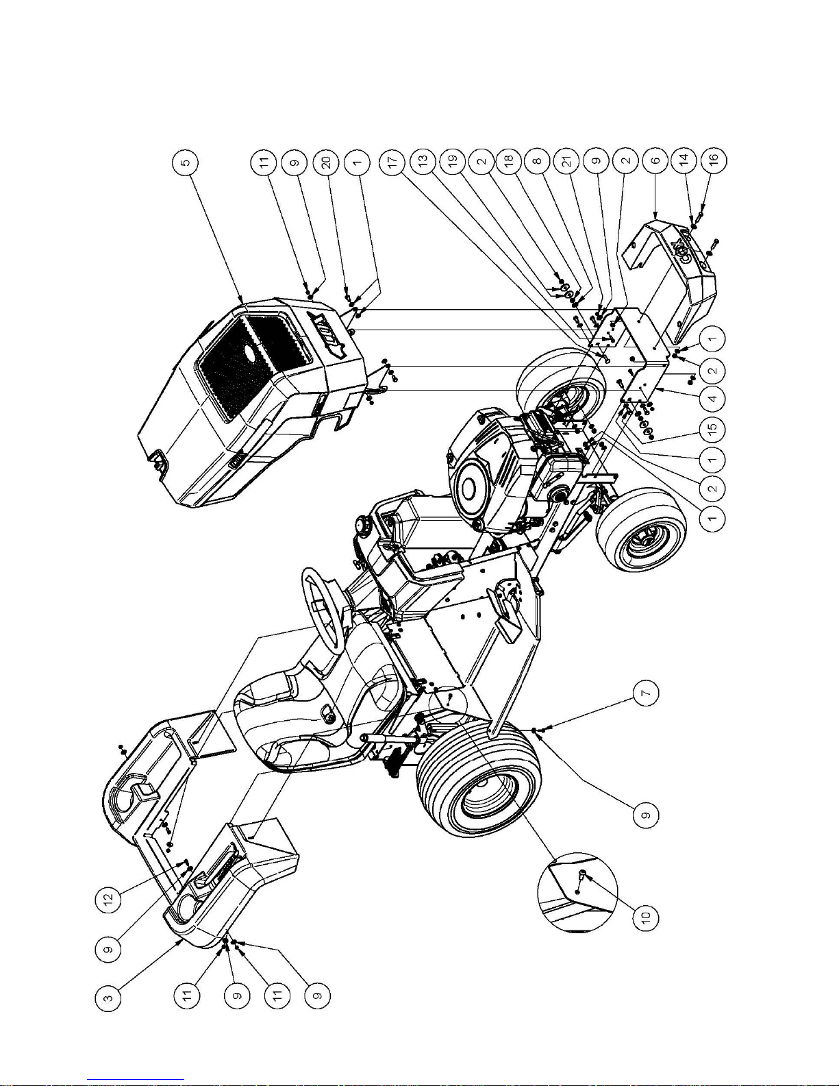
PARTS LIST: A16915G BODY - BONNET & MUDGUARD
Page 17

1 February 2016 Page 17
Owners Manual for Model A16915G Hydro Drive
PARTS LIST: A16915G BODY - BONNET & MUDGUARD
ITEM PART NUMBER DESCRIPTION QTY
1 W08MN Washer, Flat, Bright, M 8x 17x1, 2 14
2 NM8NT Nut, Hex, Nyloc, Thin, M 8, Pc6 10
3 A168022 Mudguard, Rear 1
4 A163066R Bar, Bumper, Red 1
5 Sub-Assy, Bonnet, Sman 4500, B&S, 19.0 1
6 A163014 Bumper, Front 1
7 SPPK6X20 Screw, Pan, Posi3, K 6x 20 2
8 W10MN Washer, Flat, Bright, M10x 21x1.6 2
9 W041216 Washer, Flat, Bright, 1/4"X3/4"X16g 12
10 BHSSM6X16 Screw, Button, Hex Soc, M 6x 16, Pc10.9 2
11 NM6NT Nut, Hex, Nyloc, Thin, M 6, Pc6 6
12 SH0616M Screw, Hex, M 6x 16, Pc4.6 2
13 SH0620M Screw, Hex, M 6x20, Pc4.6 2
14 W05M202 Washer, Flat, Bright, 5/16"X3/4"X14g 2
15 SH0820M Screw, Hex, M 8x 20, Pc8.8 4
16 B0835M Bolt, Hex, M8 X 35, Pc8.8 2
17 BCHSNM8X30 Bolt, Cup, Sq Neck, M8 X 30 Pc4.6. 2
18 NHM8 Nut, Hex, M8 2
19 W052003 Washer, Flat, Black, 5/16"X1-1/4"X3 4
20 SH0816M Screw, Hex, M 8x 16, Pc8.8 2
21 NHM6 Nut, Hex, M 6, Pc5 2
Page 18

1 February 2016 Page 18
Owners Manual for Model A16915G Hydro Drive
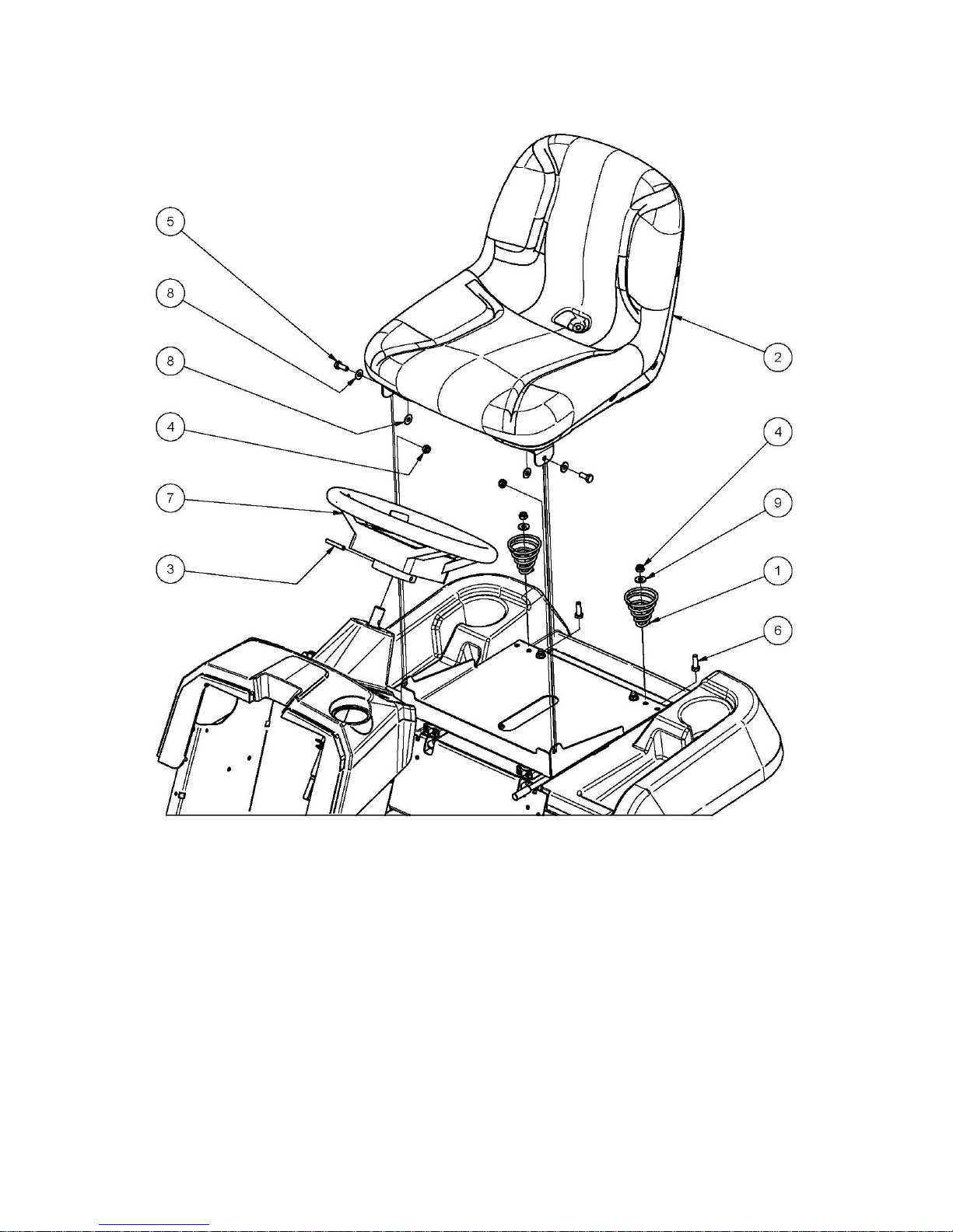
PARTS LIST: A16915G BODY - SEAT
Page 19

1 February 2016 Page 19
Owners Manual for Model A16915G Hydro Drive
PARTS LIST: A16915G BODY - SEAT
ITEM PART NUMBER DESCRIPTION QTY
1 W08MN Washer, Flat, Bright, M 8x 17x1.2 6
2 NM8NT Nut, Hex, Nyloc, Thin, M 8, Pc6 6
3 A169137B Frame, Slide, Seat 1
4 A169135R Cover, Transaxle 1
5 A126052 Kit, Adjust, Seat, 4" Travel 1
5.1 Spacer, 5/16"X1-1/4"X1/4", Plastic, Black 4
5.2 Runner, Seat 1
5.3 Adjuster, Seat, 4" Travel 1
6 N05CN Nut, Hex, Nyloc, Thick, Unc, 5/16", Gr5 4
7 BCHSNM8X25 Bolt, Cup, Sq Neck, M8 X 20 Pc4.6 4
8 NHCM8 Nut, Hex, Conelok, M 8, Pc8 4
9 W08MN Washer, Flat, Bright, M 8x 17x1.2 4
10 89073 Strip, Tape 125mm Long 2
11 A168143B Mount, Seat, Black 1
12 A120850 Seat 1
13 SH0512C Screw, Hex, Unc, 5/16"X3/4", Gr5 4
14 W051218 Washer, Flat, Bright, 5/16"X3/4"X18g 4
15 WS050216 Washer, Lock, Spring, 5/16"X1/8"X1/16" 4
16 SP1PNCSM Switch, Plunger, 1 Pole, Nc, Snap Mtg 1
17 A163060 Spring, Compression, Conical, Seat, Heavy 2
18 A168231 Cap, Spring, Seat 2
19 W05M202 Washer, Flat, Bright, 5/16"X3/4"X14g 2
20 SH0820M Screw, Hex, M 8x 20, Pc8.8 6
Page 20

1 February 2016 Page 20
Owners Manual for Model A16915G Hydro Drive
PARTS LIST: A16915G BONNET
Page 21

1 February 2016 Page 21
Owners Manual for Model A16915G Hydro Drive
PARTS LIST: A16915G BONNET
ITEM PART NUMBER DESCRIPTION QTY
1 89073 Strip, Battery 3
2 A168020 Cowl, Bonnet, Red 1
3 A168026 Grill, Bonnet, Top, Black 1
4 A168028 Grill, Bonnet, Front, Black 1
5 A168033B Mesh, Side, Left, Black 1
6 A168035B Mesh, Side, Right, Black 1
7 A168121R Nose, Bonnet, Red 1
8 A168123R Stay, Bonnet, Left, Red 1
9 A168125R Stay, Bonnet, Right, Red 1
10 A168239B Baffle, Air, Hot, Bonnet, B&S, 20.0, Black 1
11 BHSSM6X16 Screw, Button, Hex Soc, M 6x 16, Pc10.9 8
12 BHSSM6X20 Screw, Button, Hex Soc, M 6x 20, Pc10.9 2
13 DEC180 Badge, Bonnet 1
14 DEC240 Decal, Proudly Australian, Red 2
15 DEC330 Decal, Cox, 250x 80, Red 1
16 DEC333 Decal, Stockman 4500, Cox, Bonnet 2
17 NM6NT Nut, Hex, Nyloc, Thin, M 6, Pc6 10
18 NTF6.3 Nut, Hex Wash, Self-Thread, 6.3 8
19 SPPK5X16 Screw, Pan, Pozi2, K 5x 16 4
20 ST0610B Screw, Pan, Selftap, Ph2, #6-20x 5/8" 5
21 W030820 Washer, Flat, Bright, 3/16" X 1/2"X 20 G 4
22 W041216 Washer, Flat, Bright, 1/4"X3/4"X16g 4
23 W06MN Washer, Flat, Bright, M 6x 12.5x1.2 14
24 WSR12 Washer, Seal 4
Page 22

1 February 2016 Page 22
Owners Manual for Model A16915G Hydro Drive
PARTS LIST: A16915G BODY - CONSOLE
Page 23

1 February 2016 Page 23
Owners Manual for Model A16915G Hydro Drive
PARTS LIST: A16915G BODY - CONSOLE
ITEM PART NUMBER DESCRIPTION QTY
1 NCM4X1.6X9.5 Nut, Cage, M 4, 1.6 Panel, 9.5sq Hole 4
2 13012 Bush, Flanged, Nylon, 19idx22odx45l 2
3 13125 Switch, Key, 3 Posn, Magneto, 6 Term 1
4 A120870 Bezel, Switch, Key 1
5 A120872Z Washer, D, 16.1x24.0x2.5 1
6 A168009Z Bracket, Solenoid + Hourmeter 1
7 AM159 Solenoid 1
8 SH0616M Screw, Hex, M 6x 16, Pc4.6 4
9 W06MN Washer, Flat, Bright, M 6x 12.5x1.2 1
10 WM6S Washer, Lock, Int Tooth, M 6 1
11 NM6NT Nut, Hex, Nyloc, Thin, M 6, Pc6 4
12 N04C Nut, Hex, Unc, 1/4", Gr5 2
13 A168235 Control, Speed, Engine, B&S, L= 985 1
14 A168117 Switch, Pto, Push-Pull, Nodtdt, Yellow 1
15 A168024 Dash, Console 1
16 A168131B Bracket, Tank, Fuel 1
17 80037 Grommet 1
18 A168133B Strut, Console 1
19 96114 Strap, Bonnet 1
20 W041216 Washer, Flat, Bright, 1/4"X3/4"X16g 1
21 NM6NT Nut, Hex, Nyloc, Thin, M 6, Pc6 8
22 SH0616M Screw, Hex, M 6x 16, Pc4.6 1
23 W06MN Washer, Flat, Bright, M 6x 12.5x1.2 8
24 90139 Clamp, Battery 1
25 PR04M4.8 Rivet, Blind, Truss, Mon, 4.0x 8.4, 73ms 5-3 1
26 SH0612M Screw, Hex, M 6x 12, Pc4.6, Znpl 7
27 SPM4X12 Screw, Pan, X Recess, M 4 X 12, Znpl 4
28 WSM4X1.2X1.2 Washer, Lock, Spring, M 4x1.2x1.2, Znpl 4
29 W04MN Washer, Flat, Bright, M 4x 9x 0.8, Znpl 4
30 BHSSM5X12 Screw, Button, Hex Soc, M 5 X 12, Pc10.9, Znpl 2
31 W05MN Washer, Flat, Bright, M 5x 10x1.0, Znpl 2
32 NM5NT Nut, Hex, Nyloc, Thin, M5, Pc6, Znpl 2
33 A102190 Ring, Retainer, Switch, Pto 1
34 A163081 Meter, Hour 1
Page 24

1 February 2016 Page 24
Owners Manual for Model A16915G Hydro Drive
PARTS LIST: A16915G CONTROLS
Page 25

1 February 2016 Page 25
Owners Manual for Model A16915G Hydro Drive
PARTS LIST: A16915G CONTROLS
ITEM PART NUMBER DESCRIPTION QTY
1 W08MN Washer, Flat, Bright, M 8x 17x1, 2 18
2 NM8NT Nut, Hex, Nyloc, Thin, M 8, Pc6 10
3 A169183Z Rod, Brake, Park 1
4 A111050Z Bush, Pin, Locking, Unc, 5/16" 1
5 W051218 Washer, Flat, Bright, 5/16"X3/4"X18g 1
6 14038 Knob 1
7 RP04 Pin, 'R' 3
8 W10MN Washer, Flat, Bright, M10x 21x1.6 5
9 NM10NT Nut, Hex, Nyloc, Thin, M10, Pc6 1
10 W041216 Washer, Flat, Bright, 1/4"X3/4"X16g 2
11 BHSSM6X16 Screw, Button, Hex Soc, M 6x 16, Pc10.9 4
12 NM6NT Nut, Hex, Nyloc, Thin, M 6, Pc6 4
13 SH0616M Screw, Hex, M 6x 16, Pc4.6 2
14 SH0820M Screw, Hex, M 8x 20, Pc8.8 4
15 A168087Z Spacer, 8.5id, 20od, L=16 1
16 NHM8 Nut, Hex, M8 1
17 W052003 Washer, Flat, Black, 5/16"X1-1/4"X3 1
18 W06MN Washer, Flat, Bright, M 6x 12.5x1.2 10
19 B0625M Bolt, Hex, M6x25, Gr 8.8 1
20 A169189R15G Bridge, Suspension, Mower, Hydro, Red 1
21 NF06CN Nut, Hex, Nyloc, Thick, Unc, 3/8, Gr5 1
22 W061216 Washer, Flat, Bright, 3/8"X3/4"X16g 3
23 B0860M Bolt, Hex, M 8x 60, Pc8.8 5
24 A168165Z Pivot, Pedal, Drive 1
25 AM230 Bush - Plastic 4
26 A168179Z Pivot, Pedal, Brake 1
27 A168177R Lever, Pedal, Clutch/Brake 1
28 A169221R Rest, Foot, Pedal, Drive, Hydro 1
29 BHSSM6X20 Screw, Button, Hex Soc, M 6x 20, Pc10.9 3
30 A169161Z Link, Drive, Hydro 1
31 RP01 Pin, 'R' 3
32 A169171Z Lever, Actuation, Brake 1
33 B1045M Bolt, Hex, M10x 45, Pc8.8 1
34 NHM10 Nut, Hex, M10, Pc8 1
35 SH0830M Screw, Hex, M8x30, Pc8.8 1
36 A111018 Spring, Extension, Foot Brake 1
37 A169173Z Link, Clutch, Longitudinal 1
38 RE516INT End, Rod, Stamp, Unf, 5/16" Int 1
39 AM328 Pivot Bush, Lever 1
40 A169175Z Crank, Clutch 1
41 B0870M Bolt, Hex, M 8 X 70, PC8.8 1
42 RE38INTSTUD End,Rod,Stamp,Unf,3/8"Int,Stud Ball 1
43 A169181Z Link,Clutch,Transverse,Adjust 1
44 N06FC Nut,Hex,Conelok,Unf,3/8",Gr5 1
45 A169227Z Link,Disengauge,Hydro 1
46 WG12X15 Grommet 1
47 NFM6 Nut,Hex,Flange,Serated,M 6,Pc8 1
Page 26

1 February 2016 Page 26
Owners Manual for Model A16915G Hydro Drive
PARTS LIST: A16915G STEERING UPPER
Page 27

1 February 2016 Page 27
Owners Manual for Model A16915G Hydro Drive
PARTS LIST: A16915G STEERING UPPER
ITEM PART NUMBER DESCRIPTION QTY
1 B0850M Bolt, Hex, M 8x 50, Pc8.8 2
2 W08MN Washer, Flat, Bright, M 8x 17x1, 2 4
3 NM8NT Nut, Hex, Nyloc, Thin, M 8, Pc6 4
4 13012 Bush, Flanged, Nylon, 19idx22odx45l 2
5 AM017C1 Steering Shaft Bush With Collar 2
6 A168078Z Shaft, Steering, Upper 1
7 W122414 Washer, Flat, Bright, 3/4"X1-1/2"X 14g 2
8 C02 Circlip, Ext, 'E' Type 2
9 SW14H Wheel, Steering, 14", 02hub+Cover 1
10 W041216 Washer, Flat, Bright, 1/4"X3/4"X16g 8
11 W05M202 Washer, Flat, Bright, 5/16"X3/4"X14g 2
12 A168087Z Spacer, 8.5id, 20od, L=16 2
13 13242 Pin, Pivot, Front Axle 1
14 B0835M Bolt, Hex, M8 X 35, Pc8.8 2
15 A126174Z Yoke, Joint, Universal, Steering 2
16 B0625M Bolt, Hex, M6x25, Gr 8.8 12
17 NHCM6 Nut, Hex, Conelok, M 6, Pc8 12
18 AM25399J Disc, Universal Joint 2
19 A168076 Cross, Joint, Steering 1
20 C05 Circlip, Ext, "E"Type 2
21 W092016 Washer, Flat, Bright, 9/16" X 1+1/4" X 16g 2
22 A168072Z Tensioner, Chain, Steering 1
23 AM017C1 Steering Shaft Bush With Collar 2
24 WS050216 Washer, Lock, Spring, 5/16"X1/8"X1/16” 2
25 SH0825M Screw, Hex, M 8x 25, Pc8.8 2
26 DP10 Pin, Roll, Spring, 1/4"X1-3/4" 1
27 89100 Fastener, Pushon, Round, 1/4” 1
Page 28

1 February 2016 Page 28
Owners Manual for Model A16915G Hydro Drive
PARTS LIST: A16915G STEERING LOWER
Page 29

1 February 2016 Page 29
Owners Manual for Model A16915G Hydro Drive
PARTS LIST: A16915G STEERING LOWER
ITEM PART NUMBER DESCRIPTION QTY
1 B0850M Bolt, Hex, M 8x 50, Pc8.8 2
2 W08MN Washer, Flat, Bright, M 8x 17x1, 2 4
3 NM8NT Nut, Hex, Nyloc, Thin, M 8, Pc6 4
4 A168096R Beam, Axle, Front 1
5 A168099Z Axle, Stub, M10, 107.5 Deg, Left 1
6 A168101Z Axle, Stub, M10, 107.5 Deg, Right 1
7 14008 Key 2
8 A168092R Arm, Steering, Left, Red 1
9 A168094R Arm, Steering, Right, Red 1
10 GNTF3 Nipple, Grease, Straight 2
11 NM12NT Nut, Hex, Nyloc, Thin, M12, Pc6 2
12 W05M202 Washer, Flat, 5/16"X3/4"X14g 2
13 A168087Z Spacer, 8.5id, 20od, L=16 2
14 13242 Pin, Pivot, Front Axle 1
15 B0835M Bolt, Hex, M8 X 35, Pc8.8 2
16 W052003 Washer, Flat, Black, 5/16"X1-1/4"X3 1
17 SH0816M Screw, Hex, M 8x 16, Pc8.8 1
18 A168229Z Shaft, Steering, Lower, 06b-8x195 1
19 C05 Circlip, Ext, "E"Type 3
20 W092016 Washer, Flat, Bright, 9/16" X 1+1/4" X 16g 3
21 A168074Z Shaft, Steering, Idler 2
22 WS050216 Washer, Lock, Spring, 5/16"X1/8"X1/16" 1
23 SH0825M Screw, Hex, M 8x 25, Pc8.8 2
24 A168083Z Crank, Steering 1
25 A120685 Bush, Pivot, Tensioner 2
26 A168185Z Sleeve, Spacer, 1/2"Rod End 2
27 15173 Sleeve, Spacer, 3/8"-1/2"Rod End 2
28 BHSSM10X40 Screw, Button, Hex Soc, M10x 40, Pc10.9 2
29 NHCM10 Nut, Hex, Conelok, M10, Pc8 4
30 B1040M Bolt, Hex, M10x40, Pc8 2
31 RE12INT End, Rod, Stamp, Unf, 1/2" Int 4
32 N08F Nut, Hex, Unf, 1/2", Gr5 4
33 A168080 Chain, Roller 1
34 A168090Z Rod, Steering, Bent, Unf, 1/2", L=315 2
35 A168085Z Bracket, Pivot, Steering, Bottom 1
Page 30

1 February 2016 Page 30
Owners Manual for Model A16915G Hydro Drive
PARTS LIST: A16915G WHEELS
Page 31

1 February 2016 Page 31
Owners Manual for Model A16915G Hydro Drive
PARTS LIST: A16915G WHEELS
ITEM PART NUMBER DESCRIPTION QTY
1 SH1030M10.9 Screw, Hex, M10x 30, Pc10.9 2
2 W203806 Washer, Flat, 20x38x6 2
3 A120865TPC Wheel, 18x950 2
3.1 A120897S Rim 1
3.2 TT18X950-8SS Tyre, 18x 950- 8, 4PLY, Tubeless 1
3.3
Valve, Tubeless, Snap-In, Tr412, C1 Core+Vc3 Cap 1
4 NHWM12X1.5 Nut, Hex, Wheel m12x1.5, 60 Deg 8
5 W102705 Washer, Flat, Black, 10.5x27x5 2
6 WSM10X3.66X2.69 Washer, Lock, Spring, M10x3.66x2.69, Gal 2
7 AM07099C Cap, Hub, 42dia, Black 2
8 A168108 Wheel, 13x650 2
8.1 A168110 Rim 1
8.2 AM021 Sleeve, Spacer, Bearing, L=30 1
8.3
Valve, Tubeless, Snap-In, Tr412bent, C1 Core+Vc3 Cap 1
8.4 TT13x650-6SSTPC Tyre, 13x 6.50- 6, 4ply, Tubeless 1
8.5 BB204212N Bearing, Ball 2
9 W203806 Washer, Flat 2
Page 32

1 February 2016 Page 32
Owners Manual for Model A16915G Hydro Drive
PARTS LIST: A16915G ENGINE ANCILLARY
Page 33

1 February 2016 Page 33
Owners Manual for Model A16915G Hydro Drive
PARTS LIST: A16915G ENGINE ANCILLARY
ITEM PART NUMBER DESCRIPTION QTY
1 W08MN Washer, Flat, Bright, M 8x 17x1, 2 10
2 NM8NT Nut, Hex, Nyloc, Thin, M 8, Pc6 7
3 A168032 Tank, Fuel, 10.5l 1
4 CF01 Cap, Fuel 1
5 AM294 Grommet, Fuel Tap 1
6 AM293 Petrol Tap 1
7 A168235 Control, Speed, Engine, B&S, L= 985 1
8 Battery, Automotive, 12v, Cmfu1, 9pl, 240cca 1
9 SH0616M Screw, Hex, M 6x 16, Pc4.6 2
10 SH0820M Screw, Hex, M 8x 20, Pc8.8 2
11 SH0816M Screw, Hex, M 8x 16, Pc8.8 5
12 NHM6 Nut, Hex, M 6, Pc5 2
13 WS050216 Washer, Lock, Spring, 5/16"X1/8"X1/16" 4
14 A169229R Reinforce, Mount, Engine, Red - A16915g 890 (35") 1
A169233R Reinforce, Mount, Engine Red - A16915g 1055 (42") 1
15 A169223Z Guide, Belt, Drive, Front 2
16 A168147Z Tang, Clutch/Brake 1
17 A168040 Pulley, Engine 1
18 AM175 Key 1
19 A120516 Clutch/Brake, Elecmagnet 1
20 B0756F Bolt, Hex, Unf, 7/16x3-1/2", Gr5 1
21 W071416 Washer, Flat, Bright, 7/16"X7/8"X16g 2
22 WS071008 Washer, Lock, Spring, 7/16"X5/32"X1/8" 1
23 W05SE Washer, Lock, Ext Tooth, 5/16" 3
24 B0840M Bolt, Hex, M8x40, Pc8 4
25 NHCM8 Nut, Hex, Conelok, M 8, Pc8 4
26 BHSSM5X12 Screw, Button, Hex Soc, M 5 X 12, Pc10.9 2
27 W05MN Washer, Flat, Bright, M 5x 10x1.0 6
28 NM5NT Nut, Hex, Nyloc, Thin, M5, Pc6 4
29 14107 Line, Fuel, L=180 1
30 Engine, 20.0hp, V2cyl, Elec, B&S, 40N877 1
31 A172131 Muffler, Exhaust, B&S, 22.0+24.0hp 1
32 Gasket, Exhaust, B&S, 690970 2
33 Screw, Exhaust, B&S, 690341 4
34 80025 Deflector, Exhaust Gas 1
35 Deflector, Muffler, B&S 222573 1
Page 34

1 February 2016 Page 34
Owners Manual for Model A16915G Hydro Drive
PARTS LIST: A16915G WIRING
Page 35

1 February 2016 Page 35
Owners Manual for Model A16915G Hydro Drive
PARTS LIST: A16915G WIRING
ITEM PART NUMBER DESCRIPTION QTY
1 Engine 1
2 Battery, Automotive, 12v, MFU1, 9pl, 240cca 1
3 15235 Lead, Battery, Black,3term,8-570-6-330-6 1
4 13115 Lead, Battery, Red, L=400 1
5 AM159 Soleniod 1
6 AM265 Lead, Battery, Red, L=490 1
7 A16811315L Harness, Wiring, Main 1
8 Fuse, Blade, 15 Amp, Blue 1
9 13125 Switch, Key, 3 Posn, Magneto, 6 Term 1
10 A168114 Lead, Wiring, Switch, Foot 1
11 14019 Switch, Plunger 1
14020 Cover, Switch 1
12 A168117 Switch, Pto 1
13 A120516 Clutch/Brake, Elecmagnet 1
14 SP1PNCSM Switch, Plunger 1
15 A163081 Meter, Hour 1
Page 36

1 February 2016 Page 36
Owners Manual for Model A16915G Hydro Drive
PARTS LIST: A16915G DRIVE
Page 37

1 February 2016 Page 37
Owners Manual for Model A16915G Hydro Drive
PARTS LIST: A16915G DRIVE
ITEM PART NUMBER DESCRIPTION QTY
1 90293 Boss, Idler, 12dia, 16high 1
2 90294 Boss, Idler, 12dia, 3high 1
3 PIFB126598A Idler, Flat, Flg, Brg, Sealed, 12idx 65od 1
4 PIFBB02 Idler, Flat, Flg, Brg, Sealed, 17x4.00"Od 2
5 A169232 Guide, Belt, Drive, Middle 4
6 W08MN Washer, Flat, Bright, M 8x 17x1,2 15
7 14025 Boss, Idler, 17dia, 3high 2
8 A102125Z Boss, Idler, 17 Dia, 12 High 1
9 NM8NT Nut, Hex, Nyloc, Thin, M 8, Pc6 13
10 W122414 Washer, Flat, Bright, 3/4"X1-1/2"X 14g 2
11 C02 Circlip, Ext, 'E' Type 2
12 W10MN Washer, Flat, Bright, M10x 21x1.6 1
13 NM6NT Nut, Hex, Nyloc, Thin, M 6, Pc6 2
14 SH0616M Screw, Hex, M 6x 16, Pc4.6 2
15 A169012 Transaxle, Hydro, TTC, K46DR 1
16 14022 Bracket, Thrust, Hub 2
17 W05M202 Washer, Flat, Bright, 5/16"X3/4"X14g 4
18 W08MN Washer, Flat, Bright, M 8x 17x1,2 4
19 B0860M Bolt, Hex, M 8x 60, Pc8.8 4
20 NM8NT Nut, Hex, Nyloc, Thin, M 8, Pc6 4
21 A168087Z Spacer, 8.5id, 20od, L=16 1
22 W203806 Washer, Flat, 20x38x6 2
23 A169205 Adaptor, Wheel 2
24 14126 Key 2
25 14075 Cap, Hub, Rear Wheel 2
26 SH1240M1.5 Screw, Hex, M12x1.5x 40, Pc8.8 8
27 W052003 Washer, Flat, Black, 5/16"X1-1/4"X3 1
28 SH0816M Screw, Hex, M 8x 16, Pc8.8 4
29 W06MN Washer, Flat, Bright, M 6x 12.5x1.2 2
30 A102386Z Boss, Idler, 17dia, 10.5high 1
31 A169223Z Guide, Belt, Drive, Front 2
32 A168040 Pulley, Engine 1
33 AM175 Key 1
34 A120516 Clutch/Brake, Elecmagnet 1
35 B0756F Bolt, Hex, Unf, 7/16x3-1/2", Gr5 1
36 W071416 Washer, Flat, Bright, 7/16"X7/8"X16g 2
37 WS071008 Washer, Lock, Spring, 7/16"X5/32"X1/8" 1
38 A169225Z Guide, Belt, Drive, Rear 1
39 B0860M Bolt, Hex, M 8x 60, Pc8.8 5
40 RP01 Pin, 'R' 1
41 14070 Sleeve, Pivot, Drive Belt Tensioning Arm 1
42 A169151Z Arm, Tensioner, Belt, Drive, Hydro 1
43 A120685 Bush, Pivot, Tensioner 2
44 PIVBB17A88 Idler, V Belt, Brg, Sealed, 17id, A88 1
45 14025 Boss, Idler, 17dia, 3high 1
46 WS050216 Washer, Lock, Spring, 5/16"X1/8"X1/16" 1
47 SH0820M Screw, Hex, M 8x 20, Pc8. 1
48 B0870M Bolt, Hex, M 8 X 70, Pc8. 1
49 AM264 Spring 1
50 V68 Belt, V 1
Page 38

1 February 2016 Page 38
Owners Manual for Model A16915G Hydro Drive
PARTS LIST: A16915G TRANSAXLE
Page 39

1 February 2016 Page 39
Owners Manual for Model A16915G Hydro Drive
PARTS LIST: A16915G TRANSAXLE
ITEM PART NUMBER DESCRIPTION
1 K46dr Transaxle
7 T168T2024250 Vent Valve
8 T19216324360 Magnet
10 T168T2099250 Pump Shaft/Bearing Kit
11 T19215427281 Spring 25
12 T1A646089510 Bypass Shaft B
13 T1A632029520 Bypass Lever
14 T22242000100 Snap Ring,10
15 T168T2036300 Sealing Cap 30
16 T22252000350 Snap Ring C 35
18 T187Q0399940 Drain Bolt Kit
19 Order Seal Kit 0-Ring 1a P10a
20 T187T0134380 Seal Tc 153507
21 T26476080552 Tapping Screw 8 * 55
22 T26476080302 Tapping Screw 8 * 30
24 Order Repair Kit Center Case W/Ids Filter Kit
25 T19216824760 Pin 3 * 9.8
26 T168T2025220 Filter 105
27 T168T2099990 Bolt 10 * 75
28 T1A646024800 Ids Valve 1.2
29 T1A646024761 Ids Spring
30 T1A646024790 Ids Filter 300
31 Order Repair Kit Cylinder Block (Pump) Kit
32 T1A646025200 Spring
33 T168T2025250 Pump Shaft
34 T22272000120 E-Ring 12
35 T1A646034770 Bearing 6202
36 T19216824210 Motor Housing
37 T187T0034750 Thrust Bearing 51106
38 Order Repair Kit Cylinder Block Kit (Motor)
39 T19216825230 Washer 12 * 24 * 1
40 T1A646025271 Motor Shaft
41 T19215425310 Snap Ring S15
42 T187Q0325440 Motor Gear 13t Pm
43 T1A646034760 Bearing 6202
44 T187T0027060 Thrust Plastic
47 T1A646029010 Magnet Holder
49 T1A646029911 Control Shaft
50 T168T2029920 Fulcrum
51 T168T2029800 Torsion Spring
52 T168T2029740 Control Arm A
53 T1A646029400 Control Lever F
ITEM PART NUMBER DESCRIPTION
54 T168T2029360 Jerky Plate
55 T22137120000 Washer 12
56 T1A646029940 Cotter Pin 1/8in 3/4in
57 T22351060036 Spring Pin 6 * 36
58 T22351060040 Roll Pin 6 * 40
59 Order Seal Kit O-Ring 1a P14
60 T26776120002 Nut 12
61 T1A646031570 Differential Gear Kit
62 T1A646033540 Final Gear (54t)
63 T1A646033250 Final Pinion Collar
64 T1A646033410 Reduction Shaft
65 T19216833420 Washer 12 * 32 * 3.2
66 T187Q0333450 Reduction Gear 36t
67 T1A646033531 Final Pinion Gear (10t)
68 T1A646089430 Axle Shaft, Left
69 T1A646089440 Axle Shaft, Right
70 T19216334261 Thrust Washer
71 T19216834270 Ring 17
72 T19216334280 Seal 19 * 32 * 8
73 T19216834350 Bushing 19 * 25
74 T168T2034240 Bushing 19.05
75 T1A646036121 Brake Shoe
76 T1A646036160 Brake Lever
77 T1A646036171 Brake Shaft
78 T168T2036180 Brake Return Spring
79 T1A646036200 Brake Actuator
80 T22351050032 Spring Pin 5 * 32
81 Order Repair or Seal Kit O-Ring 1a P12
82 T22351040016 Spring Pin 4 * 16
84 T1A646025770 Pulley C
85 T1A646083070 Fan Black
86 T1A646083060 Wave Washer
87 T19215489090 Snap Ring
90 T22351030020 Spring Pin 3.0a * 20
91 Order Seal Kit Oil Seal 16 * 22 * .03
95 T22351030016 Spring Pin 3.0a * 16
96 T22351035040 Roll Pin 3.5 * 40
99 T1A646099500 Sealant
104 T168T2099650 Thrust Bearing/Swash Plate Kit
200 T1A646099140 Seal Kit (K46 & T40)
201 T1A646099460 Repair Kit
205 T1A646098030 Housing Kit
Page 40

1 February 2016 Page 40
Owners Manual for Model A16915G Hydro Drive
PARTS LIST: A16915G MOWER SUSPENSION
Page 41

1 February 2016 Page 41
Owners Manual for Model A16915G Hydro Drive
PARTS LIST: A16915G MOWER SUSPENSION
ITEM PART NUMBER DESCRIPTION QTY
1 W08MN Washer, Flat, Bright, M 8x 17x1, 2 9
2 NM8NT Nut, Hex, Nyloc, Thin, M 8, Pc6 7
3 A168103Z Adjuster, Cut, Transverse 1
4 A168118Z Pin 1
5 AM369 Bush 4
6 NM8NT Nut, Hex, Nyloc, Thin, M 8, Pc6 2
7 NM6NT Nut, Hex, Nyloc, Thin, M 6, Pc6 1
8 SH0620M Screw, Hex, M 6x20, Pc4.6 1
9 SH0825M Screw, Hex, M 8x 25, Pc8.8 2
10 W05M202 Washer, Flat, Bright, 5/16"X3/4"X14g 2
11 A168105R Link, Drag, Attachment, Mowing 1
12 A168197Z Rod, Adjust, Height, Cut 1
13 RP04 Pin, 'R' 1
14 A120659 Washer 1
15 AM012 Height Adjustment Pawl Push Rod Spring 1
16 AM013Q2 Height Adjustment Pawl Push Rod Button 1
17 A168219Z Bush 1
18 A168227Z Link, Height, Cut 1
19 W10MN Washer, Flat, Bright, M10x 21x1.6 2
20 NM10NT Nut, Hex, Nyloc, Thin, M10, Pc6 1
21 SH1030M10.9 Screw, Hex, M10x 30, Pc10.9 1
22 W041216 Washer, Flat, Bright, 1/4"X3/4"X16g 1
23 A168233 Sub-Assy, Aduster, Height, Cut 1
24 A168211 Grip, Hand 1
25 A168219Z Bush 1
26 W10MN Washer, Flat, Bright, M10x 21x1.6 1
27 NM10NT Nut, Hex, Nyloc, Thin, M10, Pc6 1
28 SH1030M10.9 Screw, Hex, M10x 30, Pc10.9 1
29 SH0820M Screw, Hex, M 8x 20, Pc8.8 6
30 B0835M Bolt, Hex, M8 X 35, Pc8.8 1
31 B1050M Bolt, Hex, M10 X 50 2
32 W10MN Washer, Flat, Bright, M10x 21x1.6 4
33 NM10NT Nut, Hex, Nyloc, Thin, M10, Pc6 2
34 SH0620MPC8 Screw, Hex, M 6x20, Pc8.8 4
35 W06MN Washer, Flat, Bright, M 6x 12.5x1.2 4
36 NM6N Nut, Hex, Nyloc, M 6, Pc8 4
37 A168199R Bracket, Attach, Frame, Cradle 1
38 A169189R15G Bridge, Suspension, Mower, Hydro 1
39 A168195R Link, Suspension, Mower 1
40 A168193Z Rod, Threaded 1
41 RE12INT End, Rod, Stamp, Unf, 1/2" Int 1
42 N08F Nut, Hex, Unf, 1/2", Gr5 3
43 A168191Z Bush, Half, Mount, End, Rod 2
44 B0640C Bolt, Hex, Unc, 3/8"X2-1/2", Gr5 1
45 NF06CN Nut, Hex, Nyloc, Thick, Unc, 3/8, Gr5 2
46 W061216 Washer, Flat, Bright, 3/8"X3/4"X16g 3
47 NFM8 Nut, Hex, Flange, Serated, M 8, Pc8 1
48 AM040 Spring, Extension 2
Page 42

1 February 2016 Page 42
Owners Manual for Model A16915G Hydro Drive
PARTS LIST: CA170 35”MOWING ATTACHMENT ANCILLARY COMPONENTS
Page 43

1 February 2016 Page 43
Owners Manual for Model A16915G Hydro Drive
PARTS LIST: CA170 35”MOW/ATTACHMENT ANCILLARY COMPONENTS
ITEM PART NUMBER DESCRIPTION QTY
2 A170013Z Pin 1
3 A170009Z Frame, Cradle, Idler 1
4 AM230 Bush - Plastic 2
5 A170011Z Frame, Slide, Idler 1
6 AM230 Bush - Plastic 4
7 WS06081.5 Washer, Lock, Spring, 3/8"X1/8"X3/32" 1
8 W102705 Washer, Flat, Black, 10.5x27x5 1
9 B0636C Bolt, Hex, Unc, 3/8"X2-1/4", Gr5 1
10 PIFBB06 Idler, Flat, Flg, Brg, Seal, 3/8"X16x5" 1
11 A170015Z Pin 2
12 SH0616M Screw, Hex, M 6x 16, Pc4.6 2
13 NM6NT Nut, Hex, Nyloc, Thin, M 6, Pc6 2
14 SH0616M Screw, Hex, M 6x 16, Pc4.6 1
15 NM6NT Nut, Hex, Nyloc, Thin, M 6, Pc6 1
16 A121512 Grommet, Blanking 1
17 A121513 Adaptor, Spray, Water 1
18 AM259 Deflector 1
19 A100003 Spring, Torsion, Deflector 1
20 AM274 Fastener, Pushon, Round, 1/4" 1
21 A170017Z Mount, Suspension, Rear 4
22 A170019Z Spacer, Mount, Suspension, Rear 2
23 B1040M Bolt, Hex, M10x40, Pc8 4
24 13016 Pin, 11.1 Diax327l(Plated) 1
25 SH0616M Screw, Hex, M 6x 16, Pc4.6 1
26 NM6NT Nut, Hex, Nyloc, Thin, M 6, Pc6 1
27 AM145 Spring, Extension, Weight Compensating 2
28 B1050M Bolt, Hex, M10 X 50 2
29 W10MN Washer, Flat, Bright, M10x 21x1.6 4
30 NM10NT Nut, Hex, Nyloc, Thin, M10, Pc6 2
31 V66 Belt, V 1
Page 44

1 February 2016 Page 44
Owners Manual for Model A16915G Hydro Drive
PARTS LIST: CA170 35” MOWING ATTACHMENT CUTTER COMPONENTS
Page 45

1 February 2016 Page 45
Owners Manual for Model A16915G Hydro Drive
PARTS LIST: CA170 35” MOWING ATTACHMENT CUTTER COMPONENTS
ITEM PART NUMBER DESCRIPTION QTY
1 KIT261 Kit, Housing, Cutter, 890(35") 1
1.1 Deck, Mower, Side, 890(35") 1
1.2 DEC116 Decal, Danger, Mowing Attachment 2
1.3 AM274 Fastener, Pushon, Round, 1/4" 1
1.4 A100003 Spring, Torsion, Deflector 1
2 A100054B Housing, Bearing, Flange, Guide Mount 1
3 BB255215NN Bearing, Ball 1
4 SH1030M Screw, Hex, M10x 30, Pc8.8 4
5 NM10NT Nut, Hex, Nyloc, Thin, M10, Pc6 4
6 A170003R Disc, Cutter 1
7 SKIT54N Pair, Blade+Bolt+Washer+Nut, Standard, 198 1
7.1 Blade, Mower, Swingback, Standard, 198 2
7.2 SKIT01D1 Blade Bolt & Nut Set 1
7.2.1 Nut, Hex, Nyloc, Thick, Unc, 3/8, Gr5 2
7.2.2 Washer, Wave, 3/8"X1" 2
7.2.3 Blade Bolt Grade 8 2
8 A170021 Sub-Assy, Spindle, Flanged, Cutter 1
8.1 Spindle, Flanged, Cutter0 1
8.2 A100060Z Washer, Flat, 32x45x3 1
8.3 BB305513NS Bearing, Ball 1
9 SH1025M Screw, Hex, M10 X 25, Pc 8.8 4
10 NM10NT Nut, Hex, Nyloc, Thin, M10, Pc6 4
11 A170007 Pulley, Cutter, Ci 1
12 A156017 Key 1
13 W103506 Washer, Flat, Black, 10x35x6 1
14 WW0616 Washer, Wave, 3/8"X1" 1
15 WSM10X3.66X2.69 Washer, Lock, Spring, M10x3.66x2.69, Gal 1
16 W10MN Washer, Flat, Bright, M10x 21x1.6 5
17 SH1030M10.9 Screw, Hex, M10x 30, Pc10.9 1
Page 46

1 February 2016 Page 46
Owners Manual for Model A16915G Hydro Drive
PARTS LIST: CA171 42”MOWING ATTACHMENT ANCILLARY COMPONENTS
Page 47

1 February 2016 Page 47
Owners Manual for Model A16915G Hydro Drive
PARTS LIST: CA171 42”MOWING ATTACHMENT ANCILLARY COMPONENTS
ITEM PART NUMBER DESCRIPTION QTY
2 A171019Z Frame, Cradle, Idler 1
3 AM230 Bush - Plastic 2
4 A170011Z Frame, Slide, Idler 1
5 AM230 Bush - Plastic 4
6 WS06081.5 Washer, Lock, Spring, 3/8"X1/8"X3/32" 1
7 W102705 Washer, Flat, Black, 10.5x27x5 1
8 B0636C Bolt, Hex, Unc, 3/8"X2-1/4", Gr5 1
9 PIFBB06 Idler, Flat, Flg, Brg, Seal, 3/8"X16x5" 1
10 SH0616M Screw, Hex, M 6x 16, Pc4.6 2
11 NM6NT Nut, Hex, Nyloc, Thin, M 6, Pc6 2
12 A170113Z Pin 2
13 PIFBB05 Idler, Flat, Flg, Brg, Seal, 3/8"X24x5" 1
14 W0620HD Washer, Flat, Black, 3/8"X1-1/4"X3 1
15 WS06081.5 Washer, Lock, Spring, 3/8"X1/8"X3/32" 1
16 B0640C Bolt, Hex, Unc, 3/8"X2-1/2", Gr5 1
17 A171007R Guard, Pulley, Left 1
18 A171010R Guard, Pulley, Right 1
19 13016 Pin 1
20 SH0616M Screw, Hex, M 6x 16, Pc4.6 7
21 NM6NT Nut, Hex, Nyloc, Thin, M 6, Pc6 7
22 W06MN Washer, Flat, Bright, M 6x 12.5x1.2 6
23 NM10NT Nut, Hex, Nyloc, Thin, M10, Pc6 10
24 A121513 Adaptor, Spray, Water 2
25 A121512 Grommet, Blanking, 1" 2
26 A170019Z Spacer, Mount, Suspension, Rear 2
27 A170017Z Mount, Suspension, Rear 4
28 B1040M Bolt, Hex, M10x40, Pc8 4
29 Sleeve, Roller, Deck, Cutter 4
30 KIT Wheel, includes 29,30,31 4
31 Bolt, Hex 4
32 W0620HD Washer, Flat, Black, 3/8"X1-1/4"X3 4
33 W10M Washer 4
34 AM259 Deflector 1
35 V69 Belt, V 1
36 AM274 Fastener, Pushon, Round, 1/4" 1
37 A100003 Spring, Torsion, Deflector 1
38 13016 Pin, 11.1 Diax327l(Plated) 1
39 SH0616M Screw, Hex, M 6x 16, Pc4.6 1
40 NM6NT Nut, Hex, Nyloc, Thin, M 6, Pc6 1
41 AM145 Spring, Extension 2
42 B1050M Bolt, Hex, M10 X 50 2
43 W10MN Washer, Flat, Bright, M10x 21x1.6 4
44 NM10NT Nut, Hex, Nyloc, Thin, M10, Pc6 2
Page 48

1 February 2016 Page 48
Owners Manual for Model A16915G Hydro Drive
PARTS LIST: CA171 42”MOWING ATTACHMENT CUTTER COMPONENTS
Page 49

1 February 2016 Page 49
Owners Manual for Model A16915G Hydro Drive
PARTS LIST: CA171 42”MOWING ATTACHMENT CUTTER COMPONENTS
ITEM PART NUMBER DESCRIPTION QTY
1 A100054B Housing, Bearing, Flange, Guide Mount, Black 2
2 BB255215NN Bearing, Ball 2
3 A170021 Sub-Assy, Spindle, Flanged, Cutter 2
3.1 Spindle, Flanged, Cutter 1
3.2 A100060Z Washer, Flat, 32x45x3 1
3.3 BB305513NS Bearing, Ball 1
4 A156010 Pulley, Cutter, Ci 2
5 W103506 Washer, Flat, Black, 10x35x6 2
6 WW0616 Washer, Wave 2
7 WSM10X3.66X2.69 Washer, Lock, Spring, M10x3.66x2.69, Gal 2
8 W10MN Washer, Flat, Bright, M10x 21x1.6 6
9 SH1030M10.9 Screw, Hex, M10x 30, Pc10.9 10
10 A171050Z Spacer, Sleeve, 25.2x35x 8 2
11 NM10NT Nut, Hex, Nyloc, Thin, M10, Pc6 16
12 BHSSM10X30 Screw, Button, Hex Soc, M10x 30, Pc10.9 8
13 A152011R Spacer, Disc, Cutter 2
14 A152013R Disc, Cutter 2
15 A156017 Key 2
16 KIT262 Kit, Housing, Cutter, 1055(42") 1
16.1 Deck, Mower, Side, 1055(42") 1
16.2 AM274 Fastener, Pushon, Round, 1/4" 1
16.3 A100003 Spring, Torsion, Deflector 1
16.4 DEC116 Decal, Danger, Mowing Attachment 2
16.5 DEC334 Decal, 42" Cut 1
17 KIT259 Pair, Blade+Bolt+Washer+Nut, Airflow, 163 2
17.1 Blade, Mower, Swingback, Airflow, 163 2
17.2 SKIT01D1 Blade Bolt & Nut Set 1
17.2.1 Nut, Hex, Nyloc, Thick, Unc, 3/8, Gr5 2
17.2.2 Washer, Wave 2
17.2.3 Blade Bolt Grade 8 2
Page 50

1 February 2016 Page 50
Owners Manual for Model A16915G Hydro Drive
PARTS LIST: A16915G DECALS
PART NO. DESCRIPTION CS45H20B35 CS45H20B42
95067 Non-Skid, Pedal, Brake 1 1
A122068 Non-Skid, Platform, 240 X 200 1 1
A163069 Non-Skid, Footrest, 285x100 2 2
A168223 Non-Skid, Pedal, Drive 1 1
DEC116 Decal, Danger, Mowing Attachment 2 2
DEC135 Decal, Caution, Hot Muffler 1 1
DEC136 Decal, Drive Pedal 1 1
DEC177 Badge, Steering Wheel, Oval 1 1
DEC180 Badge, Bonnet 1 1
DEC240 Decal, Proudly Australian 2 2
DEC325 Decal, Sman 4000, Cox, Hydro 1 1
DEC330 Decal, Cox, 250x 80, Red 1 1
DEC333 Decal, Sman 4500, Cox, Bonnet, Side 2 2
DEC337 Decal, Sman 4500, Deck, Do Not Step, 35" 1 NIL
DEC359 Decal, Sman 4500, Side, Left, 20.0hp, Hydro 1 1
DEC340 Decal, Sman 4500, Control, Speed 1 1
DEC341 Decal, Sman 4500, Switch, Ignition 1 1
DEC343 Decal, Sman 4500, Clutch/Brake 1 1
DEC353 Decal, Sman 4500, Deck, Do Not Step, 42" NIL 1
DEC357 Decal, Sman 4500, Side, Right, 20.0hp 1 1
DEC402 Decal, Sman 4500, Instruct, Hydro 1 1
DEC408 Decal, Sman 4500, Height, Cut 1 1
Page 51

1 February 2016 Page 51
Owners Manual for Model A16915G Hydro Drive
Specifications
Model No A16915G COX Stockman 4500 Ride-on Lawn Tractor
Product
Code
CS45H20B35
CS45H20B42
20HP (14.9Kw), Hydrostatic Drive, 890 mm (35") Side Discharge Mowing Attachment
20HP (14.9Kw), Hydrostatic Drive, 1055 mm (42") Side Discharge Mowing Attachment
Dimensions, Mass, Capacity CS45H20B42 CS45H20B35
Length
Lawn Tractor 1860 mm 1860mm
Width Lawn Tractor 889mm 889 mm
Inc Mowing Attachment Deflector Down 1321mm 1110 mm
Inc Mowing Attachment Deflector Up 1196mm 985 mm
Height 1130 mm 1130 mm
Wheel Base 1326 mm 1326 mm
Front Track [13x6.50-6 Tyres] 726 mm 726 mm
Rear Track [18x9.50-8 Tyres] 656 mm 656 mm
Dry Mass
Lawn Tractor 202.5 kgs 202.5 kgs
Mowing Attachment 35” 31.5 kgs
Mowing Attachment 42” 47.5 kgs
Total 250 kgs 234 kgs
Fuel Tank Capacity
10.5 Litre
Engine Oil Capacity Including Oil Filter 1.9 Litre
Engine Design & Performance
Model Briggs & Stratton 40N877 0025B1
Type:- Petrol, 4 Stroke, Air Cooled, Vertical PTO, 25.4 mm [1”] Shaft, Fuel
Pump, Electric Start
Intek
Cylinder Configuration Twin Cast Iron Sleeve
Valve Type Overhead
Displacement 656 cm3
Bore x Stroke 75.4 mm x 73.4 mm
Maximum Rated Gross Power to SAE J1940 & J1995 @3600 14.9 kW [20.0 hp]
Rated Engine Speed (No Load)
Maximum 3600 RPM
Idle 1800 RPM
Alternator Capacity (12 Volt DC) 9 Amps
Dry Mass
36.8 kg
Transaxle Design & Performance
Model & Type:- Hydrostatic Fluid Drive through Gear Transmission & Differential +
Hydrostatic Bypass
Disengagement + Internal Wet Disk Brake + External Reservoir Tank
Tuff Torq
K46DR
Ground Speed
(Infinitely Variable)
Forward 0-11.4 km/h
Reverse 0-6 km/h
Lubrication Capicity:- 2.3 Litres
Dry Mass 12.5 kg
Mowing Attachment Design & Performance
CA17014E CA17115G
Type: Engine PTO Shaft Mounted Electromagnetic Clutch/Brake, Spring Tensioned, Single V Belt, 4 Parallel Link Points (3 Adjustable).
1 Spindle, Right Side Discharge, 2 Swing Back Blades 890mm (35”)
2 Spindle, Right Side Discharge, 4 Swing Back Blades 1055 mm [42”]
Anti-scalp Roller 1 optional adjustable 4 Adjustable
Cut Height Range (10 Position) 15-85mm 15-85mm
Miscellaneous CS45H20B35 CS45H20B42
Minimum Uncut Grass Diameter (Left Turn) 1560mm 1385mm
Maximum Grass Cut per Hour 10000m2 12000m2
Minimum Turning Diameter
(Inside Back Tyre)
Left Turn 1200mm 1200mm
Right Turn 1200mm 1200mm
Battery (12 Volt Maintenance Free) MFU1 MFU1
Fuse (12 Volt ) Blade Type 15 Amps 15 Amps
Maximum Trailer Gross Weight
Maximum Trailer Hitch Point Load
250 kg
10 kg
250 kg
10 kg
Maintenance CS45H20B35 CS45H20B42
Fuel Unleaded Petrol, Regular or Premium or E10
Engine Oil (above + 4”C) SAE 30 A.P.I. “SF”,”SG”,”SH”,”SJ”
Transaxle Oil Initial top up SAE 10W-30 A.P.I. Class “CD” replace with 5W50 synthetic
Spark Plug Champion XC92YC Gap 0.76 mm
Mower Blades & Fasteners Part No SKIT54N KIT259 (qty 2)
Drive Belt Cox Part No V68 V68
Cutter Belt Cox Part No V66 V69
Page 52

1 February 2016 Page 52
Owners Manual for Model A16915G Hydro Drive
DIMENSIONS - CS45H20B35
Page 53

1 February 2016 Page 53
Owners Manual for Model A16915G Hydro Drive
DIMENSIONS - CS45H20B42
Page 54

70 Landseer Street
Acacia Ridge Qld 4110
Australia
PH 07 3323 2222 FAX 07 3344 6233
Web Site Address: www.coxmowers.com.au
Email: sales@coxmowers.com.au
 Loading...