

COX Stockman 4000 A16314E Owner's/operator's Manual

READ THIS MANUAL BEFORE OPERATING MACHINE
DEATH, PERSONAL INJURY AND/OR PROPERTY DAMAGE MAY OCCUR UNLESS INSTRUCTIONS IN THIS MANUAL ARE FOLLOWED
NOTE: Bring this Manual when Service & or Warranty work is required.
RIDE-ON MOWER
OWNER/OPERATORS MANUAL
Model A16314E
Live Axle Drive
CS4L17B32-17.5hp Briggs & Stratton 805mm (32”) Cut
CS4L17B38-17.5hp Briggs & Stratton 960mm (38”) Cut
CS4L16H32-16.0hp Honda 805mm (32”) Cut

19 March 2015
Page 2
OWNERS MANUAL FOR MODEL A16314E rev 1
OWNERS INFORMATION
COX MODEL NO: _________________________________
COX INVENTORY CODE NO: ________________________
COX SERIAL NO:_______________________
Located on Label inside Transmission Housing
B&S ENGINE MODEL NO:______________TYPE:____________ CODE:_______________
Located on Engine refer Engine Owners Manual
HONDA ENGINE MODEL NO:____________SERIAL NO:_______________
Located on Engine refer Engine Owners Manual
DATE OF PURCHASE:__________________________________
OWNERS NAME:
ADDRESS:
TOWN/CITY:
STATE:
AUTHORISED COX DEALER/
DISTRIBUTOR:
ADDRESS:
TOWN/CITY:
STATE:
PRE DELIVERY CHECK LIST
Check parts Assemble Service Instruction
ALWAYS KEEP THIS MANUAL IN A SAFE PLACE.

19 March 2015
Page 3
OWNERS MANUAL FOR MODEL A16314E rev 1
Read, understand, & follow all instructions in the
Owner/Operators manual.
Know the controls and how to stop the engine
quickly in an emergency.
Allow only responsible adults, who are familiar with
the instructions in this manual, to operate the machine.
Clear the area to be mowed of loose objects such as
sticks, stones, bones, wire, toys, debris, etc., which
could be picked up and thrown by the blades.
DO NOT mow whilst people, especially children, or
pets are in the mowing area.
DO NOT mow either direction on slopes beyond 15
degrees, (1 in 3.75), (27%).
Exercise extreme caution on slopes.
Reduce speed on slopes and in sharp turns to pre-
vent overturning or loss of control.
Start or stop slowly when on slopes.
Mow up and down slopes, not across the slope.
Stay alert for holes or bumps in the terrain and other
hidden hazards.
Use care when pulling loads-
a] Use only approved hitch point;
b] limit loads to those you can safely control;
c] Do not turn sharply;
d] use care when backing up.
Watch out for traffic when crossing or operating the
mower near roadways.
Stop the blades rotating before crossing surfaces
other than grass.
When using attachments, never direct discharge of
material toward bystanders nor allow anyone near
the machine while it is in operation.
Before leaving the operators position-
a] Disengage all clutches and secure cutting units;
b] Return drive pedal to neutral position and set the
parking brake;
c] Stop the engine and remove the key.
Disengage drive to attachments and stop engine-
a] Before refueling.
b] Before removing grass-catcher;
c] Before clearing blockages from chute;
d] Before checking, cleaning or working on the
mower;
e] After striking a foreign object (check the mower
for damage and make repairs before restarting and
operating the equipment);
f] If machine starts to vibrate abnormally (check immediately).
Disengage drive to attachments when transporting or
not in use.
A mower operator should be in good physical and
mental health and not under the influence of alcohol
or any drug which might impair vision, co-ordination
or judgment.
Never mow while barefoot or wearing open sandals
or thongs. Wear long trousers and heavy shoes.
It is advisable to wear suitable eye protection when
operating a mower.
Mow only in daylight or good artificial light.
Before using, always visually inspect to see that
blades, bolts and cutter assembly are not worn or
damaged. Replace worn or damaged blades and
bolts in sets to preserve balance.
Check all nuts, bolts, and screws often; always be
sure the mower is in safe operating condition.
Keep safety devices (guards and switches) in place
and in working order.
Never use the mower unless the grass catcher, or
guards provided by the manufacturer, are in position.
Ensure any replacement parts used comply with the
original manufacture’s recommendations and specifi-
cations.
Replace worn or faulty silencers.
Keep machine free of grass, leaves or other debris,
excessive oil, grease, or spilt fuel. These can be a
fire hazard.
Refuel outdoors only. Do not smoke while fueling
engine. Never remove the cap of the fuel tank or add
petrol while the engine is running or the engine is
hot. Remove fuel cap slowly to relieve any tank pressure. If fuel is spilled, do not attempt to start the
engine but move machine away from the area of the
spill and avoid creating any source of ignition until
fuel vapors have dissipated.
Check for fuel leaks while refueling, before and while
using the mower. If a fuel leak is found, do not start
or run the engine until the fuel leak is fixed and
spilled fuel is wiped away.
Do not operate engine in a confined space where
exhaust fumes (carbon monoxide) can collect.
Always mount the mower from the left or the oppo-
site side to the discharge chute.
Start the engine carefully with the cutting means dis-
engaged.
Do not over-speed the engine or alter governor set-
tings. Excessive speed is dangerous and shortens
mower life.
Stop the engine whenever you leave the mower,
even for a moment.
Store the mower in a well-ventilated room away from
naked flames such as may be found in hot water
heaters.
Do not lend or sell the mower, without the owners/
operators Manual.
SAFETY INSTRUCTIONS

19 March 2015
Page 4
OWNERS MANUAL FOR MODEL A16314E rev 1
INTRODUCTION:
The purpose of this procedure is to ensure the dealer/
distributor has assembled & made the necessary checks, &
adjustments, before the mower is operational, and
instructed the owner in its safe operation & maintenance.
This procedure begins upon receiving the crated mower and
is finalised once the mower has been either sold or leaves
the dealer/distributors premises. This is the minimum
amount of work required, however it should not be limited
to only the areas detailed in this procedure.
RESPONSIBILITY:
It is the responsibility of the dealer/distributors to ensure
that before a mower is delivered to a customer, it is in
perfect operational condition.
PROCEDURE:
CHECK SHIPPING CRATE & CONTENTS FOR DAMAGE
UNCRATE THE MOWER
CHECK COMPONENTS SUPPLIED IN SEAT
PROTECTION BAG
Engine owners Manual 1
Owner/Operator Manual 1
Tube Spanner (AM006C1) 1
Tommy Bar (AM007) 1
Ignition Keys (AM015) 2
Spark plug tube Spanner
(AM295 B&S or AM005G0 16HP Honda) 1
Steering Wheel (SW13) 1
Roll Pin (DP10) 1
Drive cone clearance Gauges (13126) 2
Seat Springs (A163060) 2
Screws M 8X 20 2
Seat spring Washers 5/16” 2
Nuts M 8 Nyloc 2
Warranty Card 1
Pre-delivery instruction Sheet 1
REMOVE SEAT PROTECTION BAG
Remove the four screws, lock washers and plain washers
securing the seat to the seat mount & remove the plastic
bag from the seat. Install the four screws, spring washers,
and plain washers, through the slots in the seat mount and
adjusted the seat to the desired position using the slots
provided, & tighten screws.
ASSEMBLE STEERING WHEEL TO MOWER
(see page 5 for exploded view)
Roll Pin Type—
To attach the steering wheel, align the hole in the steering
wheel boss to the hole in the steering shaft and use a
hammer and suitable punch to drive the DP10 roll pin in,
through the hole in the steering shaft cover into the steering
wheel and shaft. Ensure that the pin is situated centrally in
the steering wheel boss and that the steering is free to turn.
Press the steering wheel center cover into place using hand
pressure only.
ASSEMBLE SEAT MOUNT & SEAT SPRINGS TO
MOWER
(see page 5 for exploded view)
Install the two seat springs using the screws, washers, nuts,
to the transmission cover, and tighten the screws, washers,
and nuts.
Install the Seat & Mounting to the Transmission Housing
using the Screws and Nuts.
CHECK TYRE PRESSURE
Before operation ensure that all tyre pressures are equal.
The recommended pressure is 140 kpa (20 P.S.I.).
CHECK ENGINE OIL
Before operation ensure that engine oil level is to the full
mark on the dipstick. (Refer engine owners manual for
procedure & if some oil needs to be added refer Engine
owners Manual for Correct Grade).
CHECK FUEL
Ensure the fuel tap at the bottom left side of fuel tank is
turned to the on position before attempting to start engine.
(Use unleaded fuel only).
Turn off fuel tap after use.
CHECK CLUTCH PLATE ADJUSTMENT
Engage and disengage the cutter disengage lever a few
times and leave in the engaged position, this will centre the
clutch arm assembly in the neutral position. Loosen the four
square head set screws on the clutch plates using tube
spanner (AM006C1) and tommy bar (AM007). Insert the
clearance gauges supplied, one between the forward clutch
plate and cone and the other between the reverse clutch
plate and cone and hook them onto the intershaft. Slide
both clutch plates against the clearance gauges and drive
cone, tighten the set screws firmly onto the flat on the
intershaft. Remove gauges.
CHECK SAFETY SWITCH OPERATION
Foot Switch - With cutter disengage lever in disengaged
position, attempt to start the engine without depressing the
foot switch. Engine should not start.
Disengagement Switch - While sitting on seat with foot
on foot switch and cutter lever in engaged position, attempt
to start the engine. Engine should not start.
Start Switch
With Cutter Lever in disengaged position & foot switch
depressed start engine.
Seat Switch - While sitting on seat with engine running
engage cutter and lift weight from seat. Engine should cut
out.
CHECK CUTTER BELT DISENGAGEMENT
Ensure that when the cutter belt is in the disengaged
position that the belt does not overlap when squeezed
together, if this occurs adjust the cutter engage lever until
correct disengagement is achieved.
A16314E PRE-DELIVERY INSTRUCTIONS
19 March 2015
Page 5
OWNERS MANUAL FOR MODEL A16314E rev 1
ITEM PART NO DESCRIPTION QTY
1 A163064R Cover, Transmission, Red 1
2 NM8NT Nut, Hex, Nyloc, Thin, M 8,Pc6,Znpl 4
3 SH0820M Screw ,Hex, M 8x 20,Pc8.8,Znpl 6
4 W051218 Washer, Flat, 5/16"X3/4"X18g,Znpl 4
5 Sub Assembled Seat 1
6 SH0825M Screw, Hex ,M 8x 25,Pc8.8,Znpl 2
7 A163060 Spring, Conical, Seat, Heavy 2
8 W05m202 Washer, Flat 5/16"X3/4"X14g 2
9 SW13 Wheel,Steering,13",W/ Cover 1
10 DP10 Pin,Roll,Spring,1/4"X1-3/4",Znpl 1

19 March 2015
Page 6
OWNERS MANUAL FOR MODEL A16314E rev 1
IMPORTANT
RECOMMENDED FUEL
Unleaded fuel is recommended by all manufacturers of engines
fitted to Cox products.
DRIVE PRESSURE
Ensure when applying pressure to the drive pedal the wheels
start rotating, failure to adhere to this will result in clutch plate
and clutch cone damage.
SAFETY SWITCHES
Before operating machine, ensure that all safety switches are
operating correctly. Do not operate machine with faulty,
missing or damaged safety switches.
STARTING MACHINE
When starting machine, place right heel on foot switch located
on rear of footrest. Ensure that cutter is disengaged, otherwise
electric starter motor will not engage. If engine is cold move
engine speed control to choke start position and return to
desired engine speed setting when engine starts. Do not
attempt to operate engine with engine speed control lever in
choke position. (Note electric start engines fitted with recoil can
be manually started with cutter disengaged and ignition on).
BLADE WARNING
Do not use mowing attachment with broken or bent blades,
damaged or worn bolts and nuts or damaged cutter disc,
otherwise damage and premature wear will result from
vibration. Replace blades, bolts and nuts only in pairs to
maintain correct balance. Recommended blade nut torque is 36
-40Nm. Do not over tighten.
Keep both feet and hands clear
of the mowing attachment at all
times while attempting to start
or operate the machine.
WARNING
DO NOT OPERATE WITHOUT MOWING ATTACHMENT
DEFLECTOR FITTED & DOWN OR DO NOT OPERATE
WITHOUT GRASS CATCHER FITTED.
Safety footwear is recommended when operating machine.
Mount and dismount only from left hand side of machine.
Reference to left or right hand side of machine is determined by
sitting in the operating position on the machine.
Ensure machine has park brake engaged when attempting to
start engine.
Never allow engine revs to exceed more than 3600 RPM.
TO OPERATE
BEFORE STARTING/STOPPING:
See Engine Maintenance/Instruction Sheet. When stopping
engine, disengage cutter, return engine speed control to slow
position and switch off
DISENGAGING MOWING ATTACHMENT:
The cutter disengaging lever is situated on the right hand side
by the steering column. Before starting, disengage mowing
attachment by pulling lever fully back towards the operator.
For safety it is advisable at all times, other than when
mowing, that the mowing attachment be kept in the
disengaged position.
TO DRIVE FORWARD/REVERSE:
Engine speed is regulated by the engine speed control, set
engine speed control to desired engine power. Press down on
the forward section of the drive pedal for forward movement,
on the rear of the drive pedal for reverse. The amount of
pressure can be used to control the ground speed, especially in
heavier conditions. When operating the mower on slopes
greater than 10 degrees but less than 15 degrees for a
prolonged period, you may experience minor clutch fade,
should this occur, vary your mowing style eg: mow around
some flat areas, then the slope followed by the flat area again.
This will allow the drive to cool before travelling up the slope
again.
N.B. Ensure that when pressure is applied to the drive pedal
wheels are rotating or damage will occur to clutch plates.
MANOEUVRING:
Owing to the heel and toe type action of the drive pedal, it is
possible to take the machine straight from forward to reverse
and vice versa. This instant forward and reverse operation
makes the machine very manoeuvrable and the sharpest turns
can be negotiated easily and quickly.
TO BRAKE (WITH ENGINE RUNNING):
The drive pedal may be used to stop the machine. If travelling
forward push the pedal into reverse until machine stops, then
bring the pedal back to neutral position or vice versa if
travelling in reverse. Should a drive failure occur during
operation use the brake pedal situated on the left hand side
and forward of where your foot would rest during normal
operation.
TO BRAKE (WITH ENGINE STOPPED):
Use foot brake pedal only.
Damage to drive cone will occur if drive pedal is used to brake
the machine with the engine stopped.
PARKING AND TRANSPORTATION BRAKE:
Depress the lever protruding out of the left hand mudguard
downward and shift the lever to the left to engage the park
brake. Depress and shift to the right to release.
Do not engage parking brake unless the machine has
completely stopped.
Do not attempt to drive with park brake engaged damage will
occur to clutch plates and or large drive sprockets.
CUTTING HEIGHT ADJUSTMENT:
The height adjustment lever is located on the left hand side of
the machine and may be altered to suit varying conditions,
while the machine is in motion.
NOTE: When mowing slopes, keep drive pedal in forward or
reverse, depending on direction of travel. The low gearing will
prevent it from picking up excessive speed. If very steep it may
be necessary to slow engine speed slightly and /or, apply light
drive pedal pressure to the opposite drive direction. i.e. move
drive pedal into reverse when going forward down slope or into
forward when reversing down slope.
AVOID HOLDING MACHINE STATIONARY ON SLOPES
USING DRIVE PEDAL WITH ENGINE RUNNING AS
DAMAGE WILL OCCUR TO CLUTCH PLATES.
OPERATING INSTRUCTIONS

19 March 2015
Page 7
OWNERS MANUAL FOR MODEL A16314E rev 1
It is the owner’s responsibility to ensure that all-periodical
checks, necessary adjustments, services and repairs are
carried out.
STOP ENGINE - Never attempt any maintenance with the engine
running, remove spark plug lead and ensure the blades have
stopped rotating.
Before servicing, disconnect spark plug wire and ground it, disconnect
battery at negative terminal, to prevent accidental starting.
1. OIL CHANGING & FILTER REPLACEMENT (ENGINE): See Engine
Maintenance/Instructions Sheet and carry out as per Engine Manufacturers
Recommendations.
SERVICING ENGINE AIR CLEANER FOAM PRE-CLEANER— See
engine owners manual for correct method to check and service engine air
cleaner foam pre-cleaner.
2. LUBRICATION OF MACHINE: Lubrication of machine must be
carried out every 25 hours of operation or once a month, whichever occurs
first. More frequently when operated under adverse conditions.
A. OILING: A few drops of oil should be placed at the following
points: Steering linkage, disengaging linkages, height adjustment
mechanism, pivot bolt and linkages on clutch arm and clutch pedal.
B. CHAIN: Use only chain lube for lubrication of the drive and
steering chains.
C. GREASE POINTS: Grease nipples are located on top of the front
wheel stub axle.
Under no circumstances allow grease or oil to come into contact with
the Drive Cone or Clutch Plates. Should this problem occur, clean off
immediately with petrol whilst surface areas are cool and allow to dry
before operating machine.
3. TO CHECK BLADES: Stop engine. Remove spark plug lead. Side
Discharge Only, lift deflector and height adjustment control to highest
position. If necessary simply remove the blade bolt and nut using a
suitable spanner and replace worn parts.
4. ENGINE TO CLUTCH VEE BELT ADJUSTMENT: Loosen the four
engine mounting bolts. Move engine forward and adjust belt firmly.
Do not over tension belt. While maintaining tension on the engine
re-tighten bolts. Check belt tension at machine service period (25hrs)
or more frequently under heavy mowing conditions.
5. CLUTCH TO CUTTER VEE BELT ADJUSTMENT: Tension is
automatically adjusted by the belt tensioning springs.
6. CUTTER HEIGHT ADJUSTMENT: If the Mowing Attachment can
not be positioned to give a satisfactory grass cut height using the
available notches on the chassis the adjustable link can be used to
raise the Mowing Attachment to the desired height. Position the
mower on a smooth level surface and engage the mowing attachment,
lock the park brake on, and lower the Mowing Attachment to the
notch above the desired cut height. Place equal height spacers of the
desired height under the mowing attachment that can support the
mowing attachments weight and lower the Mowing Attachment onto
them. Loosen the 2 Screws located together on the front of the Rear
Link located below the front of the left foot rest. Push the Rear Link
rearwards until it stops and retighten the 2 screws. Adjust the rear
lifting link located on the middle rear of the mowing attachment by
tightening the nut until it just lifts the rear oif the mowing attachment
of the spacers. Lift the Mowing attachment off the spacers and
remove the spacers and check the cut height is as desired and the
deck is level to slightly higher (3—5 mm) at the back. Adjust height
again if required.
7. CUTTER BRAKE ADJUSTMENT: With disengagement handle in
engaged position and mowing attachment in low cut, normal clearance
between cutter head pulley and cutter head brake pad is
approximately 3mm (1/8"). To adjust clearance, remove 'R' pin from
brake pull rod, adjust to give required clearance, replace brake pull
rod and 'R' pin. Check operation after adjustment.
8. CLUTCH PLATE ADJUSTMENT: Periodically it will be found
necessary to adjust the clutch plates as the clutch cone wears. Carry
out this operation, with engine off and cutter in the engaged position.
Engage and disengage the cutter lever a few times and leave in the
engaged position, this will centre the clutch arm assembly into the neutral
position. Loosen the four square head set screws on the clutch plates
using tube spanner (AM006C1) and tommy bar (AM007). Insert the
clearance gauges supplied, one between the forward clutch plate and cone
and the other between the reverse clutch plate and cone and hook them
onto the intershaft. Slide both clutch plates against the clearance gauges
and clutch cone, tighten the set screws firmly onto the flat on the
intershaft. Remove gauges.
9. CUTTER DISENGAGING ADJUSTMENT: With the engine switched
off, engage the mowing attachment, then fully lower. Place a straight
edge vertically against the front of the front axle beam and in line with
the disengagement lever. Measure the distance between the straight
edge and the 8mm dia pin fitted with the small ‘R’ pin for the threaded
adjuster. Disengage mowing attachment and using the same method,
check the new distance. The difference should be 20 – 22mm. Engage
mowing attachment, remove ‘R’ pin and adjust threaded adjuster
accordingly. Install ‘R’ pin and re-check measurement. Due to normal
wear in clutch to cutter vee belt, the cutter disengagement lever will
move lower and touch the foot rest. When this occurs the amount of
travel will need to be re-adjusted. If a new vee belt is installed the
above settings will apply.
Start engine and raise cutter to full height stop, cutter belt should not
engage. If this occurs switch off engine, engage cutter then screw
adjuster out 1 – 2 turns then retest.
10. DRIVE CHAIN: Machines are fitted with automatic chain
adjusters. No adjustment is required. Replace chain when chain has
sagged enough to expose half the depth of the teeth on the bottom of
the large sprocket. Failure to replace worn chain will cause premature
wear of sprockets.
11. TO ADJUST STEERING CHAIN: Adjust chain by loosening the
four bolts which hold the steering idler shaft mounting brackets
(AM255) in position, slide forward to tension chain then retighten
bolts.
12. TO REMOVE MOWING ATTACHMENT: Fully lower mowing
attachment and engage, remove weight compensating spring, remove
'R' pin from rear lifting link and disconnect, remove ‘R’ pin from cutter
brake adjusting rod and disconnect, disengage mowing attachment,
remove belt, remove front pivot pin, Turn steering wheel to the left to
slide out mowing attachment. To refit, reverse the above.
13. TYRE PRESSURE: 140 Kpa (20.P.S.I.) approximately front and
rear. Uneven pressure can give an uneven finish when mowing and
may cause damage to tyres and/or tubes.
14. BATTERY MAINTENANCE: When not in use, a battery
discharges by as much as 1% a day, more when the climate is warm.
To make up for this loss, a boosting charge should be given once a
month. Disconnect battery terminals to charge, then allow to stand
minimum 1/2hr before re-connecting (re-check electrolyte level). If a
battery is not used for a period of more than three (3) months, the
terminals should be disconnected and trickle charged at two (2) amps
for two (2) hours once every three (3) months or before use.
15. SEAT ADJUSTMENT: Loosen four seat mounting bolts and slide
seat into desired position in slots and re-tighten bolts.
16. REPLACE DRIVE CHAIN: Engage park brake, jack up rear of
machine, and remove L/H wheel. Push chain tensioner arms, one at a
time, away from chain and using a suitable spanner tighten pivot bolt
lock nuts to hold them out. Release park brake then turn rear axle to
bring chain into a suitable position for removal of the chain connecting
link. Remove connecting link and chain. Inspect both sprockets for
wear or damage, replace if necessary. Install new chain and
connecting link with the link clip between the wheel and chain.
Release pivot arm nuts until arm moves freely back to chain. Engage
park brake, install wheel and lower machine.
17. CLEANING AND POLISHING POLYETHYLENE BONNET AND
REAR MUDGUARD: To keep scratches on bonnet and mudguard to
minimum, do not rub or brush off with bare hands, use a soft cloth or
a light flow of compressed air. For dirt, wash with a steady stream of
water only (no detergent), then blow off excess water with air. To
polish remove excess dust or dirt. When surface is dry, spray on an
automotive type plastic preservative and leave on for 30 to 60
seconds. Using a dry soft cloth (i.e. cheesecloth) wipe off to bring up
lustre.
GENUINE SPARE PARTS: Always use Genuine Cox Factory Made
Spare Parts. Use of non-genuine COX spares will void your warranty.
SAFETY FIRST: The use of any mechanical device can cause injury if
incorrect procedures are used. Please ensure that all family members
of intended operators read safety section of this manual thoroughly.
TORQUE SETTINGS
1/4” UNC BOLT/NUT 10Nm (84lbf in)
5/16” UNC BOLT/NUT 20Nm (180lbf in)
3/8” UNC BOLT/NUT 36Nm (27lbf ft)
7/16” UNF BOLT 68Nm (50lbf ft)
6mm BOLT/NUT 9Nm (80lbf in)
20mm NUT 100Nm (74lbf ft)
5/8” UNF NUT 100Nm (74lbf ft)
MAINTENANCE INSTRUCTIONS

19 March 2015
Page 8
OWNERS MANUAL FOR MODEL A16314E rev 1
BEFORE EXTENDED STORAGE
BEFORE EXTENDED STORAGE
BEFORE EXTENDED STORAGE
DATE / / HOURS..........................DEALER................................................
MAINTENANCE SCHEDULE
BEFORE EACH USE
BEFORE EACH USE
BEFORE EACH USE
Check engine oil level, adjust if required
Check engine air cleaner foam pre-cleaner, service if required
Check engine rotating screen/finger guard, clean if required
Check operation of safety switches, service if required
Check foot brake operation, adjust if required.
Check tyre pressures, adjust if required
Check for loose fasteners, tighten if required
Lubricate stub axles
Lubricate Drive Chain
Check mowing attachment cutter blades, bolts, nuts, disc/s,
housing, and guards for wear or damage, replace if required
Change engine oil - Clean machine - Lubricate as per required
EVERY 5 HOURS
EVERY 5 HOURS
EVERY 5 HOURS
Check engine oil level, adjust if required
Check engine air cleaner foam pre-cleaner, service if req.
Check engine rotating screen/finger guard, clean if required
Check operation of safety switches, service if required
Check foot brake operation, adjust if required.
Check tyre pressures, adjust if required
Check for loose fasteners, tighten if required
Lubricate stub axles
Check mowing attachment cutter blades, bolts, nuts, disc/s, housing,
and guards for wear or damage, replace if required
1 MONTH OR 5 HOURS W
1 MONTH OR 5 HOURS W
1 MONTH OR 5 HOURS W
HICH EVER OCCURS FIRST
HICH EVER OCCURS FIRST
HICH EVER OCCURS FIRST
Change engine oil
Check engine air cleaner foam pre-cleaner , service if required
Check engine rotating screen/finger guard, clean if required
Check foot brake operation, adjust if required
Check operation of safety switches, service if required
Check tyre pressures, adjust if required
Lubricate stub axles
Check mowing attachment cutter blades, bolts, nuts, disc/s, housing ,
and guards for damage, replace if required
Check clutch arm action, adjust if required
Check and adjust engine to clutch vee belt if required..
Check for loose fasteners, tighten if required
Check clutch to cutter vee belt and adjust cutter housing level if required
DATE / / HOURS.......................CUSTOMER................................................
3 MONTH OR 25 HOURS
3 MONTH OR 25 HOURS
3 MONTH OR 25 HOURS
WHICH EVER OCCURS FIRST
WHICH EVER OCCURS FIRST
WHICH EVER OCCURS FIRST
Change engine oil if operating under heavy load or high ambient temperature Check engine air cleaner foam pre-cleaner, service if required *
Check engine rotating screen/finger guard, clean if required *
Check foot brake operation, adjust if required
Check operation of safety switches and replace if required
Check tyre pressures, adjust if required
Lubricate stub axles
Check mowing attachment cutter blades, bolts, nuts, disc/s, housing ,
and guards for wear or damage, replace if required
Check and adjust engine to clutch vee belt if required..
Check battery condition, service if required
Check clutch to cutter vee belt and adjust cutter housing level if required
Check for loose fasteners, tighten if required
*Service more often under dusty conditions, or where air borne debris is present
*Service more often under dusty conditions, or where air borne debris is present
DATE / / HOURS..........................DEALER................................................
Change engine oil if operating under heavy load or high ambient temperature
Check engine air cleaner foam pre-cleaner, service if required *
Check engine rotating screen/finger guard, clean if required *
Check foot brake operation, adjust if required
Check operation of safety switches and replace if required
Check tyre pressures, adjust if required
Lubricate stub axles
Check mowing attachment cutter blades, bolts, nuts, disc/s, housing ,and guards for wear or damage, replace if required
Check for loose fasteners, tighten if required
Check and adjust engine to clutch vee belt if required..
Check battery condition, service if required
Check clutch to cutter vee belt and adjust cutter housing level if required
6 MONTH OR 50 HOURS
6 MONTH OR 50 HOURS
6 MONTH OR 50 HOURS
WHICH EVER OCCURS FIRST
WHICH EVER OCCURS FIRST
WHICH EVER OCCURS FIRST

19 March 2015
Page 9
OWNERS MANUAL FOR MODEL A16314E rev 1
*Service more often under dusty conditions, or where air borne debris is present
15 MONTHS OR 125 HOURS WHICH EVER OCCURS FIRST
15 MONTHS OR 125 HOURS WHICH EVER OCCURS FIRST
15 MONTHS OR 125 HOURS WHICH EVER OCCURS FIRST
9 MONTHS OR 75 HOURS WHICH EVER OCCURS F
9 MONTHS OR 75 HOURS WHICH EVER OCCURS F
9 MONTHS OR 75 HOURS WHICH EVER OCCURS F
IRST
IRST
IRST
Change engine oil if operating under heavy load or high ambient
temperature
Check engine air cleaner foam pre-cleaner, service if required *
Check engine rotating screen/finger guard, clean if required *
Check foot brake operation, adjust if required
Check operation of safety switches and replace if required
Check tyre pressures, adjust if required
Lubricate stub axles
Check mowing attachment cutter blades, bolts, nuts, disc/s, housing ,
and guards for wear or damage, replace if required
Check for loose fasteners, tighten if required
Check battery condition, service if required
Check clutch to cutter vee belt and adjust cutter housing level if required
Check and adjust engine to clutch vee belt if required..
12 MONTHS OR 100 HOURS WHICH EVER OCCURS FIRST
12 MONTHS OR 100 HOURS WHICH EVER OCCURS FIRST
12 MONTHS OR 100 HOURS WHICH EVER OCCURS FIRST
*Service more often under dusty conditions, or where air borne debris is present
DATE / / HOURS...............CUSTOMER/DEALER................................................
DATE / / HOURS..........................DEALER................................................
*Service more often under dusty conditions, or where air borne debris is present
DATE / / HOURS................CUSTOMER/DEALER................................................
18 MONTHS OR 150 HOURS WHICH EVER OCCURS FIRST
18 MONTHS OR 150 HOURS WHICH EVER OCCURS FIRST
18 MONTHS OR 150 HOURS WHICH EVER OCCURS FIRST
*Service more often under dusty conditions, or where air borne debris is present
DATE / / HOURS..........................DEALER................................................
Change engine oil filter
Change engine oil
Check engine spark plug, clean, adjust, or replace if required
If fitted clean engine exhaust spark arrester
Check engine air cleaner foam pre-cleaner , service if required *
Check engine air cleaner cartridge, service if required*
Clean engine cooling system*
Check clutch arm action, adjust if required
Replace in-line fuel filter
Check foot brake operation and lining for ware, adjust or replace if req
Lubricate stub axles
Check for loose fasteners, tighten if required
Check operation of safety switches, service if required
Check tyre pressures, adjust if required
Check drive chain and sprockets for wear, replace if required
Check steering chain an sprockets or wear, adjust if required
Check mowing attachment cutter blades, bolts, nuts, disc/s, housing,
and guards for wear or damage, replace if required
Check clutch arm action, adjust if required
Re-tension rear wheel retaining nut/s
Check battery condition, service if required
Check drive clutch plates and cone for wear or damage, adjust or
service if required
Check belts for wear or damage, replace if required
Check and adjust engine to clutch vee belt if required..
Check clutch to cutter vee belt and adjust cutter housing level if
required
Change engine oil if operating under heavy load or high ambient temperature
Check engine air cleaner foam pre-cleaner, service if required *
Check engine rotating screen/finger guard, clean if required *
Check operation of safety switches and replace if required
Check foot brake operation, adjust if required
Lubricate stub axles
Check tyre pressures, adjust if required
Check battery condition, service if required
Check mowing attachment cutter blades, bolts, nuts, disc/s, housing,
and guards for wear or damage, replace if required
Check for loose fasteners, tighten if required
Check clutch to cutter vee belt and adjust cutter housing level if required
Check and adjust engine to clutch vee belt if required..
Change engine oil
If fitted clean engine exhaust spark arrestor
Check engine air cleaner foam pre-cleaner , service if required *
Check engine rotating screen/finger guard , clean if required *
Check foot brake operation and lining for ware, adjust or replace if
required
Check operation of safety switches, service if required
Check tyre pressures, adjust if required
Lubricate stub axles
Check steering chain an sprockets or wear, adjust if required
Check mowing attachment cutter blades, bolts, nuts, disc/s, housing,
and guards for wear or damage, replace if required
Check belts for wear or damage, replace if required
Check drive chain and sprockets for wear, replace if required
If fitted check mowing attachment brake pad for wear, replace if required
Check drive clutch plates and cone for wear or damage,
adjust or service if required
Check clutch arm action, adjust if required
Check battery condition, service if required
Check for loose fasteners, tighten if required
Check and adjust engine to clutch vee belt if required..
Check clutch to cutter vee belt and adjust cutter housing level if required

19 March 2015
Page 10
OWNERS MANUAL FOR MODEL A16314E rev 1
21 MONTHS OR 175 HOURS WHICH EVER OCCURS FIRST
21 MONTHS OR 175 HOURS WHICH EVER OCCURS FIRST
21 MONTHS OR 175 HOURS WHICH EVER OCCURS FIRST
Change engine oil if operating under heavy load or high ambient
temperature
Check engine air cleaner foam pre-cleaner, service if required *
Check engine rotating screen/finger guard, clean if required *
Check foot brake operation, adjust if required
Check operation of safety switches and replace if required
Check tyre pressures, adjust if required
Lubricate stub axles
Check mowing attachment cutter blades, bolts, nuts, disc/s, housing ,
and guards for wear or damage, replace if required
Check battery condition, service if required
Check for loose fasteners, tighten if required
Check clutch to cutter vee belt and adjust cutter housing level if required
Check and adjust engine to clutch vee belt if required..
24 MONTHS OR 200 HOURS WHICH EVER OCCURS FIRST
24 MONTHS OR 200 HOURS WHICH EVER OCCURS FIRST
24 MONTHS OR 200 HOURS WHICH EVER OCCURS FIRST
*Service more often under dusty conditions, or where air borne debris is present
DATE / / HOURS...............CUSTOMER/DEALER................................................
Replace engine oil filter
Change engine oil
Check engine spark plug, clean, adjust, or replace if required
If fitted clean engine exhaust spark arrestor
Check engine air cleaner foam pre-cleaner , service if required *
Check engine air cleaner cartridge, service if required
Clean engine cooling system*
Check foot brake operation and lining for ware, adjust or replace if
required
Check operation of safety switches, service if required
Check tyre pressures, adjust if required
Lubricate stub axles
Check steering chain an sprockets or wear, adjust if required
Check mowing attachment cutter blades, bolts, nuts, disc/s, housing,
and guards for wear or damage, replace if required
Check belts for wear or damage, replace if required
Check drive chain and sprockets for wear, replace if required
Check drive clutch plates and cone for wear or damage,
adjust or service if required
Check clutch arm action, adjust if required
Check battery condition, service if required
Check for loose fasteners, tighten if required
Check and adjust engine to clutch vee belt if required..
Check clutch to cutter vee belt and adjust cutter housing level if required
*Service more often under dusty conditions, or where air borne debris is present
DATE / / HOURS..........................DEALER................................................
27 MONTHS OR 225 HOURS WHICH EVER OCCURS FIRST
27 MONTHS OR 225 HOURS WHICH EVER OCCURS FIRST
27 MONTHS OR 225 HOURS WHICH EVER OCCURS FIRST
Change engine oil if operating under heavy load or high ambient temperature
Check engine air cleaner foam pre-cleaner, service if required *
Check engine rotating screen/finger guard, clean if required *
Check foot brake operation, adjust if required
Check operation of safety switches and replace if required
Check tyre pressures, adjust if required
Lubricate stub axles
Check mowing attachment cutter blades, bolts, nuts, disc/s, housing ,
and guards for wear or damage, replace if required
Check battery condition, service if required
Check for loose fasteners, tighten if required
Check clutch to cutter vee belt and adjust cutter housing level if required
Check and adjust engine to clutch vee belt if required..
*Service more often under dusty conditions, or where air borne debris is present
DATE / / HOURS................CUSTOMER/DEALER................................................
30 MONTHS OR 250 HOURS WHICH EVER OCCURS FIRST
30 MONTHS OR 250 HOURS WHICH EVER OCCURS FIRST
30 MONTHS OR 250 HOURS WHICH EVER OCCURS FIRST
Change engine oil
If fitted clean engine exhaust spark arrestor
Check engine air cleaner foam pre-cleaner , service if required *
Check engine rotating screen/finger guard , clean if required *
Check foot brake operation and lining for ware, adjust or replace if
required
Check operation of safety switches, service if required
Check tyre pressures, adjust if required
Lubricate stub axles
Check steering chain an sprockets or wear, adjust if required
Check mowing attachment cutter blades, bolts, nuts, disc/s, housing, and guards for wear or damage, replace if required
Check belts for wear or damage, replace if required
Check drive chain and sprockets for wear, replace if required
Check drive clutch plates and cone for wear or damage,
adjust or service if required
Check clutch arm action, adjust if required
Check battery condition, service if required
Check for loose fasteners, tighten if required
Check and adjust engine to clutch vee belt if required..
Check clutch to cutter vee belt and adjust cutter housing level if
required
*Service more often under dusty conditions, or where air borne debris is present
DATE / / HOURS..........................DEALER................................................

19 March 2015
Page 11
OWNERS MANUAL FOR MODEL A16314E rev 1
33 MONTHS OR 275 HOURS WHICH EVER OCCURS FIRST
33 MONTHS OR 275 HOURS WHICH EVER OCCURS FIRST
33 MONTHS OR 275 HOURS WHICH EVER OCCURS FIRST
Change engine oil if operating under heavy load or high ambient
temperature
Check engine air cleaner foam pre-cleaner, service if required *
Check engine rotating screen/finger guard, clean if required *
Check foot brake operation, adjust if required
Check operation of safety switches and replace if required
Check tyre pressures, adjust if required
Lubricate stub axles
Check mowing attachment cutter blades, bolts, nuts, disc/s, housing , and guards for wear or damage, replace if required
Check battery condition, service if required
Check for loose fasteners, tighten if required
Check clutch to cutter vee belt and adjust cutter housing level if
required
Check and adjust engine to clutch vee belt if required..
*Service more often under dusty conditions, or where air borne debris is present
DATE / / HOURS.................CUSTOMER/DEALER................................................
36 MONTHS OR 300 HOURS WHICH EVER OCCURS FIRST
36 MONTHS OR 300 HOURS WHICH EVER OCCURS FIRST
36 MONTHS OR 300 HOURS WHICH EVER OCCURS FIRST
Replace engine oil filter
Change engine oil
Check engine spark plug, clean, adjust, or replace if required
If fitted clean engine exhaust spark arrestor
Check engine air cleaner foam pre-cleaner , service if required *
Check engine air cleaner cartridge, service if required
Clean engine cooling system*
Check foot brake operation and lining for ware, adjust or replace if
required
Check operation of safety switches, service if required
Check tyre pressures, adjust if required
Lubricate stub axles
Check steering chain an sprockets or wear, adjust if required
Check mowing attachment cutter blades, bolts, nuts, disc/s, housing, and guards for wear or damage, replace if required
Check belts for wear or damage, replace if required
Check drive chain and sprockets for wear, replace if required
Check drive clutch plates and cone for wear or damage,
adjust or service if required
Check clutch arm action, adjust if required
Check battery condition, service if required
Check for loose fasteners, tighten if required
Check and adjust engine to clutch vee belt if required..
Check clutch to cutter vee belt and adjust cutter housing level if
required
*Service more often under dusty conditions, or where air borne debris is present
DATE / / HOURS..........................DEALER................................................
We are proud that you have purchased a Cox product and urge you to follow these instructions
to obtain the maximum life for your machine. If in doubt check with your supplier.
19 March 2015
Page 12
OWNERS MANUAL FOR MODEL A16314E rev 1
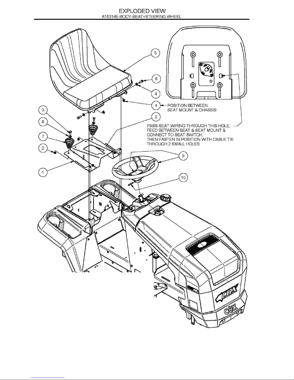
EXPLODED VIEW: A16314E BODY- SEAT & STEERING WHEEL

19 March 2015
Page 13
OWNERS MANUAL FOR MODEL A16314E rev 1
ITEM PART NO DESCRIPTION QTY
1 A163064R Cover, Transmission, Red 1
2 NM8NT Nut, Hex, Nyloc, Thin, M 8,Pc6 4
3 SH0820M Screw ,Hex, M 8x 20,Pc8.8 6
4 W051218 Washer, Flat, 5/16"X3/4"X18g 4
5 A163056 Seat 1
6 SH0825M Screw, Hex ,M 8x 25,Pc8.8 2
7 A163060 Spring, Conical, Seat, Heavy 2
8 W05m202 Washer, Flat 5/16"X3/4"X14g 2
9 SW13 Wheel,Steering,13",W/ Cover 1
10 DP10 Pin,Roll,Spring,1/4"X1-3/4" 1
PARTS LIST: A16314E BODY- SEAT & STEERING WHEEL
19 March 2015
Page 14
OWNERS MANUAL FOR MODEL A16314E rev 1
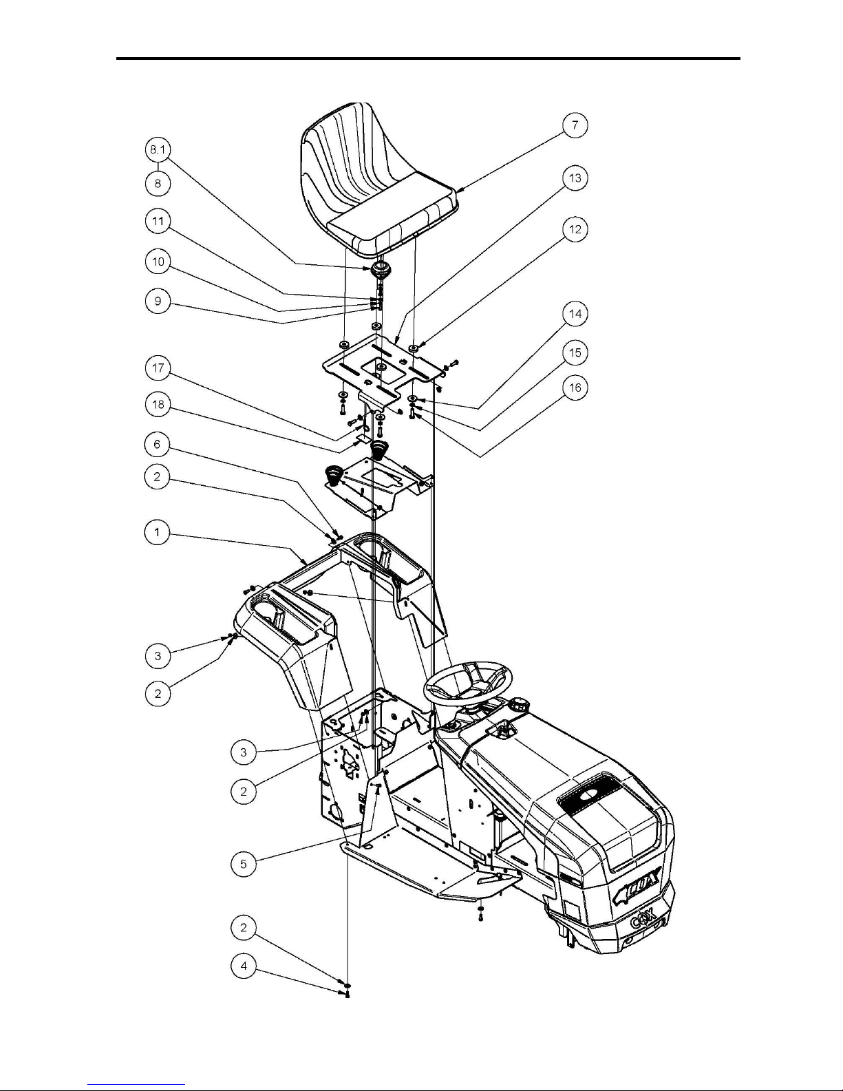
EXPLODED VIEW: A16314E BODY- SEAT, COVER & MUDGUARD

19 March 2015
Page 15
OWNERS MANUAL FOR MODEL A16314E rev 1
ITEM PART NUMBER DESCRIPTION QTY
1 A163012 Mudguard, Rear, Red 1
2 W041216 Washer, Flat, Bright, 1/4"X3/4"X16g 8
3 NM6NT Nut, Hex, Nyloc, Thin, M 6,Pc6 4
4 SPPK6X20 Screw, Pan 2
5 BHSSM6X16 Screw, Button, Hex Soc, M 6x 16,Pc10.9 2
6 SH0616M Screw, Hex, M 6x 16,Pc4.6 4
7 A140110 Seat 1
8 AM16512F Switch, Seat 1
8.1 SP1PNCSM Switch, Plunger 1
9 BHSSC0410 Screw, Button, Hex Soc,Unc,1/4"X 5/8",Pc10.9 2
10 WS040816 Washer, Lock, Spring, 1/4"X3/32"X1/16" 2
11 W040818 Washer, Flat, 1/4"X1/2"X18g 2
12 W103208 Washer, Flat, 10.5x32x8 4
13 A163062R Mount, Seat 1
14 W0620HD Washer, Flat, 3/8"X1-1/4"X3 4
15 WS06081.5 Washer, Lock, Spring, 3/8"X1/8"X3/32" 4
16 B0620C Bolt, Hex, Unc, 3/8"X1-1/4",Gr5 4
17 CABLETIES Cable Ties 1
18 DEC246 Decal, Instruct, Wiring, Switch, Seat 1
PARTS LIST: A16314E BODY- SEAT, COVER & MUDGUARD
 Loading...