

Operator’s Manual
Nellcor
TM
Bedside SpO2 Patient Monitoring System

© 2018 Covidien. All rights reserved. COVIDIEN, COVIDIEN with logo, and Covidien logo and Positive Results for Life are U.S.
and internationally registered trademarks of Covidien AG. ™* brands are trademarks of their respective owners. Other
brands are trademarks of a Covidien company.

Table of Contents
1 Introduction
1.1 Overview . . . . . . . . . . . . . . . . . . . . . . . . . . . . . . . . . . . . . . . . . . . . . . . . . . . . . . . . . . . . . . . . . . . 1-1
1.2 Safety Information . . . . . . . . . . . . . . . . . . . . . . . . . . . . . . . . . . . . . . . . . . . . . . . . . . . . . . . . . . 1-1
1.2.1 Safety Symbols . . . . . . . . . . . . . . . . . . . . . . . . . . . . . . . . . . . . . . . . . . . . . . . . . . . . . . . . . . . . . . . . . . . . . . .1-1
1.2.2 Warnings . . . . . . . . . . . . . . . . . . . . . . . . . . . . . . . . . . . . . . . . . . . . . . . . . . . . . . . . . . . . . . . . . . . . . . . . . . . . .1-2
1.2.3 Cautions . . . . . . . . . . . . . . . . . . . . . . . . . . . . . . . . . . . . . . . . . . . . . . . . . . . . . . . . . . . . . . . . . . . . . . . . . . . . . .1-4
1.3 Obtaining Technical Assistance . . . . . . . . . . . . . . . . . . . . . . . . . . . . . . . . . . . . . . . . . . . . . . 1-5
1.3.1 Technical Services . . . . . . . . . . . . . . . . . . . . . . . . . . . . . . . . . . . . . . . . . . . . . . . . . . . . . . . . . . . . . . . . . . . .1-5
1.3.2 Related Documents . . . . . . . . . . . . . . . . . . . . . . . . . . . . . . . . . . . . . . . . . . . . . . . . . . . . . . . . . . . . . . . . . .1-5
1.4 Warranty Information . . . . . . . . . . . . . . . . . . . . . . . . . . . . . . . . . . . . . . . . . . . . . . . . . . . . . . . 1-5
2 Product Overview
2.1 Overview . . . . . . . . . . . . . . . . . . . . . . . . . . . . . . . . . . . . . . . . . . . . . . . . . . . . . . . . . . . . . . . . . . . 2-1
2.2 Product Description . . . . . . . . . . . . . . . . . . . . . . . . . . . . . . . . . . . . . . . . . . . . . . . . . . . . . . . . . 2-1
2.3 Indications for Use . . . . . . . . . . . . . . . . . . . . . . . . . . . . . . . . . . . . . . . . . . . . . . . . . . . . . . . . . . 2-2
2.4 Product Views . . . . . . . . . . . . . . . . . . . . . . . . . . . . . . . . . . . . . . . . . . . . . . . . . . . . . . . . . . . . . . 2-3
2.4.1 Front Panel and Display Components . . . . . . . . . . . . . . . . . . . . . . . . . . . . . . . . . . . . . . . . . . . . . . . . .2-3
2.4.2 Rear Panel . . . . . . . . . . . . . . . . . . . . . . . . . . . . . . . . . . . . . . . . . . . . . . . . . . . . . . . . . . . . . . . . . . . . . . . . . . .2-7
2.4.3 Product and Carton Label Symbols . . . . . . . . . . . . . . . . . . . . . . . . . . . . . . . . . . . . . . . . . . . . . . . . . . .2-7
3 Installation
3.1 Overview . . . . . . . . . . . . . . . . . . . . . . . . . . . . . . . . . . . . . . . . . . . . . . . . . . . . . . . . . . . . . . . . . . . 3-1
3.2 Safety Reminders . . . . . . . . . . . . . . . . . . . . . . . . . . . . . . . . . . . . . . . . . . . . . . . . . . . . . . . . . . . 3-1
3.3 Unpacking and Inspection . . . . . . . . . . . . . . . . . . . . . . . . . . . . . . . . . . . . . . . . . . . . . . . . . . . 3-2
3.4 Setup . . . . . . . . . . . . . . . . . . . . . . . . . . . . . . . . . . . . . . . . . . . . . . . . . . . . . . . . . . . . . . . . . . . . . . 3-3
3.4.1 Connecting to Power . . . . . . . . . . . . . . . . . . . . . . . . . . . . . . . . . . . . . . . . . . . . . . . . . . . . . . . . . . . . . . . . .3-3
3.4.2 Using the Internal Battery . . . . . . . . . . . . . . . . . . . . . . . . . . . . . . . . . . . . . . . . . . . . . . . . . . . . . . . . . . . . .3-4
3.4.3 Connecting a Nellcor™ Pulse Oximetry Sensor . . . . . . . . . . . . . . . . . . . . . . . . . . . . . . . . . . . . . . . .3-5
4 Operation
4.1 Overview . . . . . . . . . . . . . . . . . . . . . . . . . . . . . . . . . . . . . . . . . . . . . . . . . . . . . . . . . . . . . . . . . . . 4-1
4.2 Safety Reminders . . . . . . . . . . . . . . . . . . . . . . . . . . . . . . . . . . . . . . . . . . . . . . . . . . . . . . . . . . . 4-1
4.3 User Interface . . . . . . . . . . . . . . . . . . . . . . . . . . . . . . . . . . . . . . . . . . . . . . . . . . . . . . . . . . . . . . 4-2
4.3.1 Turning on the Monitoring System . . . . . . . . . . . . . . . . . . . . . . . . . . . . . . . . . . . . . . . . . . . . . . . . . . . 4-2
4.3.2 Turning off the Monitoring System . . . . . . . . . . . . . . . . . . . . . . . . . . . . . . . . . . . . . . . . . . . . . . . . . . .4-3
4.4 Menu Options Navigation . . . . . . . . . . . . . . . . . . . . . . . . . . . . . . . . . . . . . . . . . . . . . . . . . . . 4-3
4.4.1 Menu Structure . . . . . . . . . . . . . . . . . . . . . . . . . . . . . . . . . . . . . . . . . . . . . . . . . . . . . . . . . . . . . . . . . . . . . . .4-5
4.4.2 QUICK ACCESS Menus . . . . . . . . . . . . . . . . . . . . . . . . . . . . . . . . . . . . . . . . . . . . . . . . . . . . . . . . . . . . . . . .4-6
4.4.3 OPTIONS Menu . . . . . . . . . . . . . . . . . . . . . . . . . . . . . . . . . . . . . . . . . . . . . . . . . . . . . . . . . . . . . . . . . . . . . . . 4-7
Operator’s Manual i

4.4.4 ALARM/LIMITS Menu . . . . . . . . . . . . . . . . . . . . . . . . . . . . . . . . . . . . . . . . . . . . . . . . . . . . . . . . . . . . . . . .4-10
4.4.5 PATIENT MODE Menu . . . . . . . . . . . . . . . . . . . . . . . . . . . . . . . . . . . . . . . . . . . . . . . . . . . . . . . . . . . . . . .4-12
4.4.6 SpO
WAVEFORM Menu . . . . . . . . . . . . . . . . . . . . . . . . . . . . . . . . . . . . . . . . . . . . . . . . . . . . . . . . . . . . .4-13
2
4.5 Managing Alarms and Alarm Limits . . . . . . . . . . . . . . . . . . . . . . . . . . . . . . . . . . . . . . . . . 4-14
4.5.1 Audible Alarm Indicators . . . . . . . . . . . . . . . . . . . . . . . . . . . . . . . . . . . . . . . . . . . . . . . . . . . . . . . . . . . .4-15
4.5.2 Visual Alarm Indicators . . . . . . . . . . . . . . . . . . . . . . . . . . . . . . . . . . . . . . . . . . . . . . . . . . . . . . . . . . . . . . .4-16
4.6 Factory Defaults . . . . . . . . . . . . . . . . . . . . . . . . . . . . . . . . . . . . . . . . . . . . . . . . . . . . . . . . . . . 4-17
4.7 Maintenance Reminder . . . . . . . . . . . . . . . . . . . . . . . . . . . . . . . . . . . . . . . . . . . . . . . . . . . . 4-18
5 Data Management
5.1 Overview . . . . . . . . . . . . . . . . . . . . . . . . . . . . . . . . . . . . . . . . . . . . . . . . . . . . . . . . . . . . . . . . . . . 5-1
5.2 Tabular Trend Data . . . . . . . . . . . . . . . . . . . . . . . . . . . . . . . . . . . . . . . . . . . . . . . . . . . . . . . . . 5-1
5.3 Graphical Trend Data . . . . . . . . . . . . . . . . . . . . . . . . . . . . . . . . . . . . . . . . . . . . . . . . . . . . . . . 5-2
5.4 External Data Communication . . . . . . . . . . . . . . . . . . . . . . . . . . . . . . . . . . . . . . . . . . . . . . . 5-3
5.4.1 Nurse Call Interface . . . . . . . . . . . . . . . . . . . . . . . . . . . . . . . . . . . . . . . . . . . . . . . . . . . . . . . . . . . . . . . . . . . 5-3
5.4.2 Trend Data Download . . . . . . . . . . . . . . . . . . . . . . . . . . . . . . . . . . . . . . . . . . . . . . . . . . . . . . . . . . . . . . . . 5-5
5.4.3 Firmware Upgrades . . . . . . . . . . . . . . . . . . . . . . . . . . . . . . . . . . . . . . . . . . . . . . . . . . . . . . . . . . . . . . . . .5-16
6 Performance Considerations
6.1 Overview . . . . . . . . . . . . . . . . . . . . . . . . . . . . . . . . . . . . . . . . . . . . . . . . . . . . . . . . . . . . . . . . . . . 6-1
6.2 Oximetry Considerations . . . . . . . . . . . . . . . . . . . . . . . . . . . . . . . . . . . . . . . . . . . . . . . . . . . . 6-1
6.2.1 Pulse Rates . . . . . . . . . . . . . . . . . . . . . . . . . . . . . . . . . . . . . . . . . . . . . . . . . . . . . . . . . . . . . . . . . . . . . . . . . . .6-1
6.2.2 Saturation . . . . . . . . . . . . . . . . . . . . . . . . . . . . . . . . . . . . . . . . . . . . . . . . . . . . . . . . . . . . . . . . . . . . . . . . . . . . 6-1
6.3 Performance Considerations . . . . . . . . . . . . . . . . . . . . . . . . . . . . . . . . . . . . . . . . . . . . . . . . 6-1
6.3.1 Overview . . . . . . . . . . . . . . . . . . . . . . . . . . . . . . . . . . . . . . . . . . . . . . . . . . . . . . . . . . . . . . . . . . . . . . . . . . . . .6-1
6.3.2 Patient Conditions . . . . . . . . . . . . . . . . . . . . . . . . . . . . . . . . . . . . . . . . . . . . . . . . . . . . . . . . . . . . . . . . . . . . 6-2
6.3.3 Sensor Performance Considerations . . . . . . . . . . . . . . . . . . . . . . . . . . . . . . . . . . . . . . . . . . . . . . . . . . 6-2
6.3.4 Reducing EMI (Electromagnetic Interference) . . . . . . . . . . . . . . . . . . . . . . . . . . . . . . . . . . . . . . . . . 6-4
6.4 Obtaining Technical Assistance . . . . . . . . . . . . . . . . . . . . . . . . . . . . . . . . . . . . . . . . . . . . . 6-5
7 Preventive Maintenance
7.1 Overview . . . . . . . . . . . . . . . . . . . . . . . . . . . . . . . . . . . . . . . . . . . . . . . . . . . . . . . . . . . . . . . . . . . 7-1
7.2 Cleaning . . . . . . . . . . . . . . . . . . . . . . . . . . . . . . . . . . . . . . . . . . . . . . . . . . . . . . . . . . . . . . . . . . . 7-1
7.3 Recycling and Disposal . . . . . . . . . . . . . . . . . . . . . . . . . . . . . . . . . . . . . . . . . . . . . . . . . . . . . 7-2
7.4 Battery Maintenance . . . . . . . . . . . . . . . . . . . . . . . . . . . . . . . . . . . . . . . . . . . . . . . . . . . . . . . 7-2
7.5 Periodic Safety Checks . . . . . . . . . . . . . . . . . . . . . . . . . . . . . . . . . . . . . . . . . . . . . . . . . . . . . . 7-3
7.6 Service . . . . . . . . . . . . . . . . . . . . . . . . . . . . . . . . . . . . . . . . . . . . . . . . . . . . . . . . . . . . . . . . . . . . . 7-4
ii Operator’s Manual

Table of Contents
8 Troubleshooting
8.1 Overview . . . . . . . . . . . . . . . . . . . . . . . . . . . . . . . . . . . . . . . . . . . . . . . . . . . . . . . . . . . . . . . . . . . 8-1
8.2 General . . . . . . . . . . . . . . . . . . . . . . . . . . . . . . . . . . . . . . . . . . . . . . . . . . . . . . . . . . . . . . . . . . . . 8-1
8.3 Error Conditions . . . . . . . . . . . . . . . . . . . . . . . . . . . . . . . . . . . . . . . . . . . . . . . . . . . . . . . . . . . . 8-2
8.4 Return . . . . . . . . . . . . . . . . . . . . . . . . . . . . . . . . . . . . . . . . . . . . . . . . . . . . . . . . . . . . . . . . . . . . . 8-4
9 Accessories
9.1 Overview . . . . . . . . . . . . . . . . . . . . . . . . . . . . . . . . . . . . . . . . . . . . . . . . . . . . . . . . . . . . . . . . . . . 9-1
9.2 Nellcor™ Pulse Oximetry Sensors . . . . . . . . . . . . . . . . . . . . . . . . . . . . . . . . . . . . . . . . . . . . 9-1
9.3 Optional Equipment . . . . . . . . . . . . . . . . . . . . . . . . . . . . . . . . . . . . . . . . . . . . . . . . . . . . . . . . 9-3
9.4 Biocompatibility Testing . . . . . . . . . . . . . . . . . . . . . . . . . . . . . . . . . . . . . . . . . . . . . . . . . . . . 9-4
10 Theory of Operations
10.1 Overview . . . . . . . . . . . . . . . . . . . . . . . . . . . . . . . . . . . . . . . . . . . . . . . . . . . . . . . . . . . . . . . . . . 10-1
10.2 Theoretical Principles . . . . . . . . . . . . . . . . . . . . . . . . . . . . . . . . . . . . . . . . . . . . . . . . . . . . . . 10-1
10.3 Automatic Calibration . . . . . . . . . . . . . . . . . . . . . . . . . . . . . . . . . . . . . . . . . . . . . . . . . . . . . . 10-2
10.4 Functional Testers and Patient Simulators . . . . . . . . . . . . . . . . . . . . . . . . . . . . . . . . . . . 10-2
10.5 Unique Technologies . . . . . . . . . . . . . . . . . . . . . . . . . . . . . . . . . . . . . . . . . . . . . . . . . . . . . . 10-3
10.5.1 Functional versus Fractional Saturation . . . . . . . . . . . . . . . . . . . . . . . . . . . . . . . . . . . . . . . . . . . . . .10-3
10.5.2 Measured versus Calculated Saturation . . . . . . . . . . . . . . . . . . . . . . . . . . . . . . . . . . . . . . . . . . . . . .10-3
10.5.3 Data Update Period, Data Averaging, and Signal Processing . . . . . . . . . . . . . . . . . . . . . . . . . .10-4
10.6 SatSeconds™ Alarm Management Feature . . . . . . . . . . . . . . . . . . . . . . . . . . . . . . . . . .10-5
10.6.1 First SpO
10.6.2 Second SpO
10.6.3 Third SpO
10.6.4 The SatSeconds™ Safety Net . . . . . . . . . . . . . . . . . . . . . . . . . . . . . . . . . . . . . . . . . . . . . . . . . . . . . . . . .10-8
Event . . . . . . . . . . . . . . . . . . . . . . . . . . . . . . . . . . . . . . . . . . . . . . . . . . . . . . . . . . . . . . . . . . . . .10-5
2
Event . . . . . . . . . . . . . . . . . . . . . . . . . . . . . . . . . . . . . . . . . . . . . . . . . . . . . . . . . . . . . . . . . .10-6
2
Event . . . . . . . . . . . . . . . . . . . . . . . . . . . . . . . . . . . . . . . . . . . . . . . . . . . . . . . . . . . . . . . . . . . .10-7
2
11 Product Specifications
11.1 Overview . . . . . . . . . . . . . . . . . . . . . . . . . . . . . . . . . . . . . . . . . . . . . . . . . . . . . . . . . . . . . . . . . . 11-1
11.2 Physical Characteristics . . . . . . . . . . . . . . . . . . . . . . . . . . . . . . . . . . . . . . . . . . . . . . . . . . . . 11-1
11.3 Electrical . . . . . . . . . . . . . . . . . . . . . . . . . . . . . . . . . . . . . . . . . . . . . . . . . . . . . . . . . . . . . . . . . . 11-2
11.4 Environmental Conditions . . . . . . . . . . . . . . . . . . . . . . . . . . . . . . . . . . . . . . . . . . . . . . . . . . 11-2
11.5 Tone Definition . . . . . . . . . . . . . . . . . . . . . . . . . . . . . . . . . . . . . . . . . . . . . . . . . . . . . . . . . . . . 11-3
11.6 Performance Specifications . . . . . . . . . . . . . . . . . . . . . . . . . . . . . . . . . . . . . . . . . . . . . . . . 11-4
11.7 Sound Pressure . . . . . . . . . . . . . . . . . . . . . . . . . . . . . . . . . . . . . . . . . . . . . . . . . . . . . . . . . . . . 11-5
11.8 Product Compliance . . . . . . . . . . . . . . . . . . . . . . . . . . . . . . . . . . . . . . . . . . . . . . . . . . . . . . .11-6
11.9 Manufacturer’s Declaration . . . . . . . . . . . . . . . . . . . . . . . . . . . . . . . . . . . . . . . . . . . . . . . . 11-6
11.9.1 Electromagnetic Compatibility (EMC) . . . . . . . . . . . . . . . . . . . . . . . . . . . . . . . . . . . . . . . . . . . . . . . .11-6
11.9.2 Sensor and Cable Compliance . . . . . . . . . . . . . . . . . . . . . . . . . . . . . . . . . . . . . . . . . . . . . . . . . . . . . 11-11
Operator’s Manual iii

11.9.3 Safety Tests . . . . . . . . . . . . . . . . . . . . . . . . . . . . . . . . . . . . . . . . . . . . . . . . . . . . . . . . . . . . . . . . . . . . . . . . 11-11
11.10 Essential Performance . . . . . . . . . . . . . . . . . . . . . . . . . . . . . . . . . . . . . . . . . . . . . . . . . . . . 11-14
A Clinical Studies
A.1 Overview . . . . . . . . . . . . . . . . . . . . . . . . . . . . . . . . . . . . . . . . . . . . . . . . . . . . . . . . . . . . . . . . . . . A-1
A.2 Methods . . . . . . . . . . . . . . . . . . . . . . . . . . . . . . . . . . . . . . . . . . . . . . . . . . . . . . . . . . . . . . . . . . . A-1
A.3 Study Population . . . . . . . . . . . . . . . . . . . . . . . . . . . . . . . . . . . . . . . . . . . . . . . . . . . . . . . . . . . A-2
A.4 Study Results . . . . . . . . . . . . . . . . . . . . . . . . . . . . . . . . . . . . . . . . . . . . . . . . . . . . . . . . . . . . . . . A-2
A.5 Adverse Events or Deviations . . . . . . . . . . . . . . . . . . . . . . . . . . . . . . . . . . . . . . . . . . . . . . . A-3
A.6 Conclusion . . . . . . . . . . . . . . . . . . . . . . . . . . . . . . . . . . . . . . . . . . . . . . . . . . . . . . . . . . . . . . . . . A-4
iv Operator’s Manual

List of Tables
Table1-1.Safety Symbol Definitions...............................................................................1-1
Table2-1.Display Colors ......................................................................................................2-6
Table2-2.Symbol Descriptors ...........................................................................................2-7
Table3-1.Standard Items ....................................................................................................3-2
Table4-1.Menu Structure and Available Options......................................................4-5
Table4-2.Alarm Conditions ............................................................................................ 4-15
Table4-3.Audio Status...................................................................................................... 4-16
Table4-4. Parameter Ranges and Factory Defaults ............................................... 4-17
Table5-1.Nurse Call Relay Pins States for NORMALLY + .........................................5-5
Table5-2.Nurse Call Relay Pins States for NORMALLY –..........................................5-5
Table5-3.Operating Status Codes................................................................................... 5-9
Table8-1.Common Problems and Resolutions ..........................................................8-2
Table9-1.Nellcor™ Pulse Oximetry Sensor Models and Patient Sizes ................9-2
Table11-1.Transport, Storage, and Operating Condition Ranges.................... 11-2
Table11-2.Tone Definitions............................................................................................ 11-3
Table11-3.Trends ............................................................................................................... 11-4
Table11-4.Pulse Oximetry Sensor Accuracy and Ranges .................................... 11-5
Table11-5.Sound Pressure in Decibels....................................................................... 11-5
Table11-6.Electromagnetic Emissions Guidelines................................................. 11-7
Table11-7.Electromagnetic Immunity Guidelines ................................................. 11-8
Table11-8.Recommended Separation Distances................................................... 11-9
Table11-9.Test Specifications for Enclosure Port Immunity to RF
Wireless Communications Equipment..................................................11-10
Table11-10.Cables and Sensors..................................................................................11-11
Table11-11.Earth Leakage and Touch Current......................................................11-12
Table11-12.Patient Leakage Current ........................................................................11-13
TableA-1.Demographic Data........................................................................................... A-2
TableA-2.SpO
Accuracy for Nellcor™ Sensors vs. CO-oximeters....................... A-2
2
Operator’s Manual v

Page Left Intentionally Blank
vi Operator’s Manual

List of Figures
Figure2-1. Front and Side Panel Components ......................................................................... 2-3
Figure2-2. Display Components.................................................................................................... 2-4
Figure2-3. Rear Panel Components ............................................................................................. 2-7
Figure3-1.Connecting a Pulse Oximetry Sensor to Interface Cable ................................. 3-6
Figure4-1.Sample Initial Screen..................................................................................................... 4-3
Figure4-2.Save Change Screen...................................................................................................... 4-4
Figure4-3.QUICK ACCESS SpO
Figure4-4.QUICK ACCESS PR Menu with Alarm Audio OFF................................................. 4-6
Figure4-5.Volume Selection............................................................................................................ 4-8
Figure4-6.Volume Selection............................................................................................................ 4-8
Figure4-7.Response Mode Menu.................................................................................................. 4-9
Figure4-8.Delete All Trend Data Menu Item ...........................................................................4-10
Figure4-9.Alarm/Limits Menu Options .....................................................................................4-11
Figure4-10.Patient Mode Menu...................................................................................................4-12
Figure4-11.Highlighting the Waveform Display Area .........................................................4-13
Figure4-12.SpO
Waveform Menu .............................................................................................4-13
2
Figure5-1.Tabular Trend Data Screen.......................................................................................... 5-1
Figure5-2.Graphical Trend Data Screen...................................................................................... 5-2
Figure5-3.Nurse Call Interface Pin Layout.................................................................................. 5-4
Figure5-4.Trend Data Download Option ................................................................................... 5-7
Figure5-5.Trend Data Download Status..................................................................................... 5-8
Figure5-6.Sample Trend Data Printout.....................................................................................5-10
Figure5-7.Sample Bridge Driver Installer Window ...............................................................5-11
Figure5-8.Sample New Hardware Wizard Screen .................................................................5-12
Figure5-9.Sample DEVICE MANAGER Button Under Hardware Tab ..............................5-13
Figure5-10.Sample Hardware List in Device Manager Window ......................................5-14
Figure5-11.Sample Initial USB to UART Bridge Properties Window...............................5-15
Figure5-12.Sample Baud Rate List Under Port Settings Tab.............................................5-16
Figure10-1.Oxyhemoglobin Dissociation Curve ...................................................................10-4
Figure10-2.Series of SpO
Figure10-3.First SpO
Figure10-4.Second SpO
Figure10-5.Third SpO
2
Event: No SatSeconds™ Alarm..........................................................10-6
2
Event: No SatSeconds™ Alarm ...................................................10-7
2
Event: Triggers SatSeconds™ Alarm .............................................10-8
2
FigureA-1.Modified Bland-Altman Plot.......................................................................................A-3
Menu with Audio Alarm Selected .................................. 4-6
2
Events................................................................................................10-5
Operator’s Manual vii

Page Left Intentionally Blank
viii Operator’s Manual
1 Introduction
1.1 Overview
This manual contains information for operating the Nellcor™ bedside SpO2 patient monitoring
system.
Note:
Before use, carefully read this manual, accessory Instructions for Use, and all precautionary information
and specifications.
1.2 Safety Information
This section contains important safety information related to general use of the Nellcor™
bedside SpO
throughout the manual. The Nellcor™ bedside SpO2 patient monitoring system will be referred
to as the “monitoring system” throughout this manual.
patient monitoring system. Other important safety information appears
2
1.2.1 Safety Symbols
Symbol Definition
WARNING
Warnings alert users to potential serious outcomes (death, injury, or adverse events) to
the patient, user, or environment.
Caution
Identifies conditions or practices that could result in damage to the equipment or
other property.
Note
Notes provide additional guidelines or information.
Table1-1.Safety Symbol Definitions
1-1

Introduction
1.2.2 Warnings
WARNING:
Explosion hazard — Do not use the monitoring system in the presence of flammable anesthetics.
WARNING:
Explosion hazard — Do not use the battery with other manufacturer's batteries. Do not use
different types or models of batteries such as dry batteries, nickel-metal hydride batteries, or
Lithium-ion batteries together.
WARNING:
Do not use any monitoring system or pulse oximetry cables, sensors, or connectors that appear
damaged.
WARNING:
As with all medical equipment, carefully route patient cabling to reduce the possibility of patient
entanglement or strangulation.
WARNING:
Do not simultaneously touch the patient and the signal input, signal output, or any other
connectors.
WARNING:
Do not lift or carry the monitoring system by the pulse oximetry sensor or pulse oximetry interface
cable. The cable may disconnect and cause the monitoring system to drop on a patient or cause
damage to monitoring system surfaces.
WARNING:
To ensure patient safety, do not place the monitoring system in any location where it might drop
on the patient.
WARNING:
The LCD panel contains toxic chemicals. Do not touch broken LCD panels. Physical contact with a
broken LCD panel can result in transmission or ingestion of toxic substances.
WARNING:
Always disconnect and remove the monitoring system and sensors during magnetic resonance
imaging (MRI) scanning. Attempting to use the monitoring system during an MRI procedure could
cause burns or adversely affect the MRI image or the monitoring system's accuracy.
1-2 Operator’s Manual

WARNING:
The monitoring system is intended only as an adjunct in patient assessment. It must be used in
conjunction with clinical signs and symptoms.
WARNING:
The values displayed by the monitoring system can be affected by patient conditions, excessive
patient movement, sensors, environmental conditions, and nearby external electromagnetic
conditions.
WARNING:
The monitoring system is intended for use in a hospital or hospital-type environment by trained
medical personnel.
WARNING:
Failure to cover the pulse oximetry sensor site with opaque material in high ambient light
conditions may result in inaccurate measurements. Refer to the appropriate sections of this
manual for specific safety information.
Safety Information
WARNING:
The monitoring system is not defibrillator-proof. It may remain attached to the patient during
defibrillation or during use of an electrosurgical unit; readings may be inaccurate during
defibrillation and shortly thereafter.
WARNING:
The monitoring system may retain trend data from multiple patients if transferring the
monitoring system from one patient to another.
WARNING:
Any connections between this monitoring system and other devices must comply with applicable
medical systems safety standards such as IEC 60601-1. Failure to do so could result in unsafe
leakage current and grounding conditions.
WARNING:
Do not silence or decrease the volume of the audible alarm if patient safety could be
compromised.
WARNING:
Do not preset different alarm limits for the same or similar equipment within a single area.
Operator’s Manual 1-3

Introduction
1.2.3 Cautions
Caution:
The monitoring system may not operate properly if it is operated or stored at conditions outside
the ranges stated in this manual, or if it is subjected to excessive shock or dropping.
Caution:
Do not spray, pour, or spill any liquid on the monitoring system, its accessories, connectors,
switches, or openings in the chassis, since this may cause damage to the monitoring system. Never
place fluids on the monitoring system. If fluid spills on the monitoring system, remove batteries,
wipe dry immediately, and have it serviced to ensure no hazard exists.
Caution:
Accessory equipment connected to the monitoring system's data interface must be certified
according to IEC 60950-1 for data-processing equipment. All combinations of equipment must be
in compliance with IEC 60601-1 Requirements for Medical Electrical Systems. Anyone who
connects additional equipment to the signal input or signal output port configures a medical
system and is therefore responsible for ensuring the system complies with the requirements of IEC
60601-1, IEC 60601-1-2:2007, and IEC 60601-1-2:2014.
Caution:
When connecting the monitoring system to any instrument, verify proper operation before clinical
use. Both the monitoring system and the instrument connected to it must be connected to a
grounded outlet.
Caution:
For best product performance and measurement accuracy, use only accessories supplied or
recommended by Covidien. Use accessories according to the manufacturer's instructions for use and
institutional standards. Use only accessories that have passed the recommended biocompatibility
testing in compliance with ISO10993-1.
Caution:
Where the integrity of the external protective conductor in the installation or its arrangement is in
doubt, the monitoring system operates from its battery.
Caution:
This monitoring system generates, uses, and can radiate radio frequency energy and, if not
installed and used in accordance with the instructions, may cause harmful interference to other
devices in the vicinity.
Caution:
Inspect the monitoring system and all accessories before use to ensure there are no signs of
physical damage or improper function. Do not use if damaged.
1-4 Operator’s Manual

Obtaining Technical Assistance
Obtaining Technical Assistance
1.3
1.3.1 Technical Services
For technical information and assistance, contact Covidien or a local Covidien representative.
Covidien Technical Services: Patient Monitoring
15 Hampshire Street
Mansfield, MA 02048 USA
1.800.635.5267, 1.925.463.4635,
or contact a local Covidien representative
www.covidien.com
When calling Covidien or a local Covidien representative, have the monitoring system serial
number available. Provide the firmware version number listed at power-on self-test (POST).
1.3.2 Related Documents
Nellcor™ Bedside SpO2 Patient Monitoring System Operator’s Manual —
Provides basic information
for operating the monitoring system and troubleshooting errors or malfunctions. Before using the
monitoring system, thoroughly read this manual.
Nellcor™ Pulse Oximetry Sensor Instructions for Use — Guides sensor selection and usage. Before
attaching any of the various Covidien-approved pulse oximetry sensors to the monitoring system,
refer to the individual Instructions for Use.
Saturation Accuracy Grid — Provides sensor-specific guidance related to desired SpO
accuracy measurements. Available online at
Nellcor™ Bedside SpO
Patient Monitoring System Service Manual — Provides information to
2
www.covidien.com.
saturation
2
qualified service technicians for use when servicing the monitoring system.
1.4 Warranty Information
The information contained in this document is subject to change without notice. Covidien makes
no warranty of any kind with regard to this material, including, but not limited to, the implied
warranties or merchantability and fitness for a particular purpose. Covidien shall not be liable for
errors contained herein or for incidental or consequential damages in connection with the
furnishing, performance, or use of this material.
Operator’s Manual 1-5

Introduction
Page Left Intentionally Blank
1-6 Operator’s Manual

2 Product Overview
2.1 Overview
WARNING:
Patient conditions may result in erroneous readings. If the measurements are suspect, verify the
reading using another clinically accepted measurement method.
This chapter contains basic information about the Nellcor™ bedside SpO2 patient monitoring
system. The monitoring system relies on unique oximetry technology and design to provide
hospitals, clinicians, and caregivers accurate, timely data, which includes a number of
parameters.
• Arterial blood oxygen saturation (SpO
relative to the sum of oxyhemoglobin and deoxyhemoglobin
• Pulse rate (PR) — Detected heart pulsations in beats per minute
• Plethysmographic waveform (Pleth) — A non-normalized waveform that represents relative
pulsatile strength
• Operating status — State of the monitoring system, including alarm conditions and messages
• Patient data — Real-time trend data on the current patient
• Sensor messages — Detected real-time information on attached patient sensor
2.2 Product Description
The Nellcor™ bedside SpO2 patient monitoring system provides continuous, noninvasive
monitoring of functional oxygen saturation of arterial hemoglobin (SpO2) and pulse rate.
) — Functional measure of oxygenated hemoglobin
2
2-1

Product Overview
Indications for Use
2.3
WARNING:
The monitoring system is intended only as an adjunct in patient assessment. It must be used in
conjunction with clinical signs and symptoms.
The Nellcor™ Bedside SpO2 Patient Monitoring System is indicated for the continuous noninvasive monitoring of functional oxygen saturation of arterial hemoglobin (SpO2) and pulse rate.
The Nellcor™ Bedside SpO2 Patient Monitoring System is intended for prescription use only with
neonatal, pediatric, and adult patients, and for patients who are well or poorly perfused, in
hospitals, hospital-type facilities, and intra-hospital transport.
Note:
• Hospital use typically covers such areas as general care floors (GCFs), operating rooms, special
procedure areas, intensive and critical care areas within the hospital, and in hospital-type facilities.
• Hospital-type facilities include physician office-based facilities, sleep labs, skilled nursing facilities,
surgicenters, and sub-acute centers.
• Intra-hospital transport includes transport of a patient within the hospital or hospital-type facility.
2-2 Operator’s Manual
Product Views
2.4
2.4.1 Front Panel and Display Components
Front and Side Panels
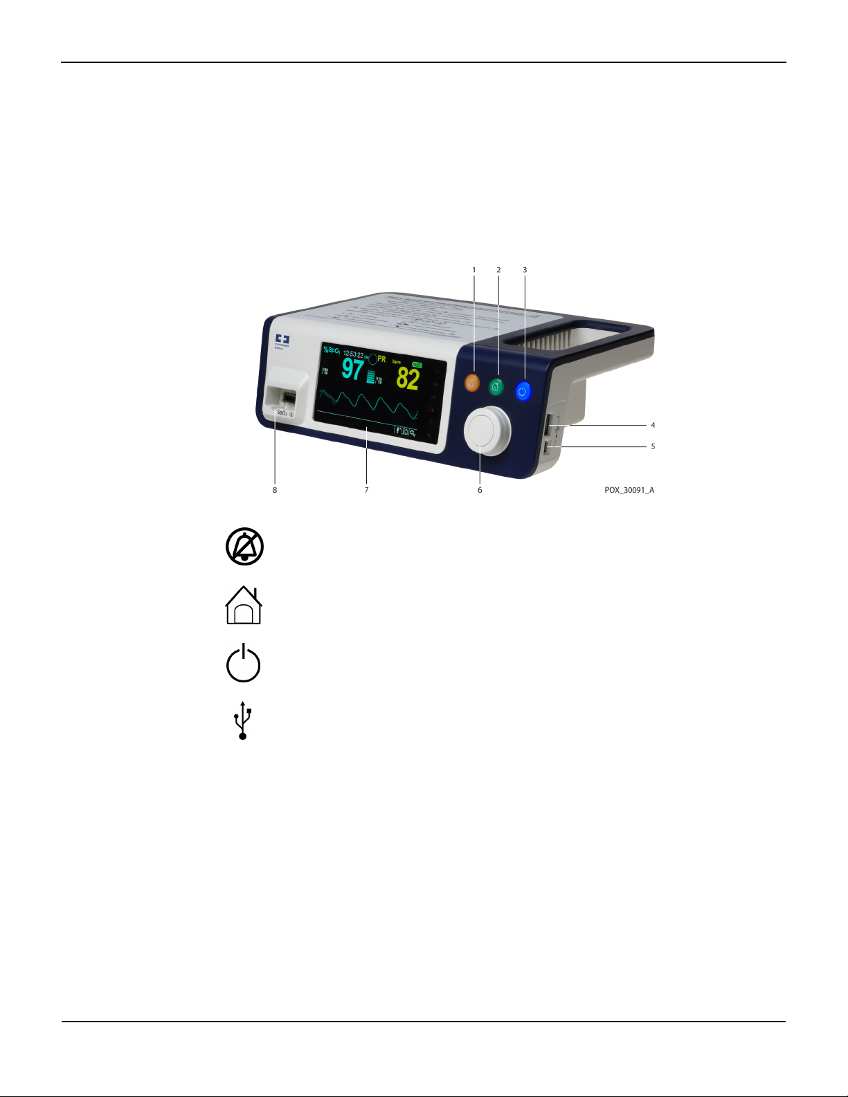
Figure2-1. Front and Side Panel Components
Product Views
1 Silence Alarm button Press to toggle between disabling and re-enabling the
audible alarm. Reference Menu Options Navigation, p. 4-3.
2 Return button Press to exit a menu displayed on the screen and go to the
main screen. Reference Menu Options Navigation, p. 4-3.
3 Power On/Off button Press and hold to turn on or off the monitoring system,
using AC power or Lithium-ion batteries. Reference Menu
Options Navigation, p. 4-3.
4 USB port (USB A type) Use USB interface for firmware upgrades.
5 USB port (mini USB B type) Use mini-USB interface for trend data downloads.
6 Jog dial Use to navigate and control display and monitoring
system functions.
7 LCD display panel Use to monitor all graphic and numeric patient
information as well as status conditions and warning
messages.
8 SpO
connector Use to connect to the interface cable and SpO2 sensor.
2
Operator’s Manual 2-3
Product Overview
Display
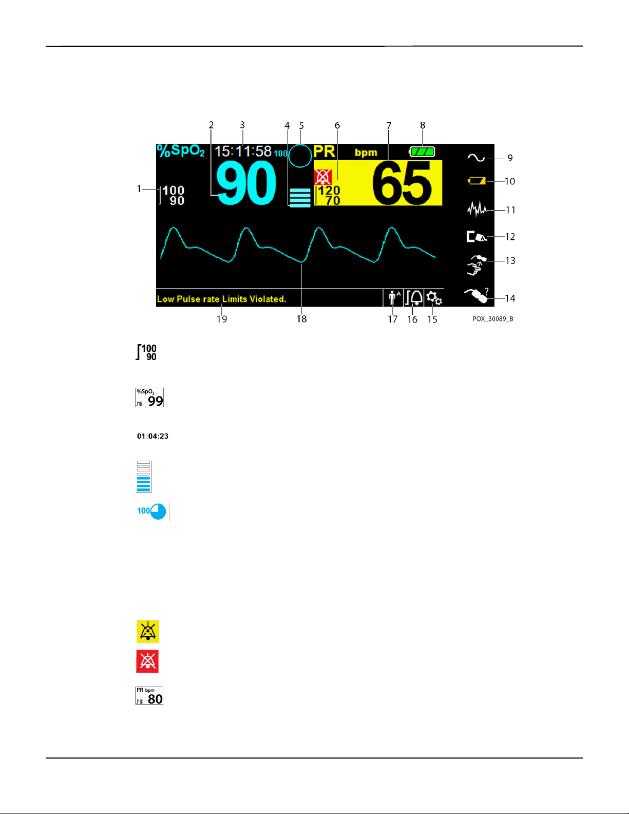
Figure2-2. Display Components
1 Upper and lower alarm limits Reflects upper and lower SpO
and pulse rate alarm limits. An
2
alarm sounds each time patient saturation or pulse rate values
violate these alarm limits.
2 SpO
real-time value Indicates hemoglobin oxygen saturation levels. Current upper
2
and lower alarm limit settings appear as smaller values to the
left of the dynamic SpO
value.
2
3 Time Indicates the current time in hours, minutes, and seconds.
4 Pulse amplitude (blip bar) Indicates pulse beat and the relative (non-normalized) pulse
amplitude. As the detected pulse becomes stronger, more bars
light with each pulse.
5 SatSeconds™ icon The SatSeconds™ feature provides alarm management for mild
or brief SpO
limit violations. When the SatSeconds™ feature is
2
enabled, the SatSeconds™ icon fills in the clockwise direction as
the SatSeconds™ alarm management system detects SpO
2
readings outside of the limits setting. The SatSeconds™ icon
empties in the counterclockwise direction when SpO
readings
2
are within limits. When the SatSeconds™ icon reaches full, a
medium priority alarm sounds. The adult default setting is 100.
Reference SatSeconds™ Alarm Management Feature, p. 10-5.
6 Alarm silenced icon
The yellow icon indicates Alarm Silenced. This indicator also
shows the time remaining in the alarm silence period.
Audio OFF icon
The red icon indicates Audio OFF.
7 Pulse rate real-time value Displays the pulse rate in beats per minute. Current upper and
lower alarm limit settings appear as smaller values to the left of
the dynamic pulse rate value.
2-4 Operator’s Manual

Product Views
8 Battery status icon Displays the battery charge remaining on an internal 5- or 10-
hour battery.
• Charged Battery — A steady green battery icon indicates
the monitoring system is running on internal battery
power and the battery is fully charged.
• Low Battery — A low priority alarm occurs when the
remaining battery power is only enough for 15 minutes of
operation. The flashing yellow alarm message Low
Battery appears. Users cannot silence this alarm while
running on battery power. Connect the monitoring
system to AC power to stop the alarm.
• Critically Low-Battery — A high priority alarm occurs for
about five (5) minutes before the monitoring system shuts
off. The flashing red alarm message Critically Low-
Battery appears. When no charge remains, the
monitoring system automatically shut down. Connect the
monitoring system to AC power to avoid any loss of trend
data or settings.
9 AC power indicator Lights continuously when connected to AC power.
10 Battery charge indicator Lights when the monitoring system is charging an internal 5- or
10-hour battery.
11 Interference indicator Lights when the monitoring system detects degraded quality in
the incoming signal.It is common for it to intermittently light as
the monitoring system dynamically adjusts the amount of data
required for measuring SpO
and pulse rate. When lit
2
continuously, the monitoring system has extended the amount
of data required for measuring SpO
and pulse rate. In this case,
2
fidelity in tracking rapid changes in these values may be
reduced.
1
12 Sensor disconnect indicator Appears when the sensor is not connected to the monitoring
system.
13 Sensor off indicator Appears when the sensor is not on the patient.
14 Sensor message indicator Appears when the sensor is invalid.
15 Options menu area Visible when users utilize the jog dial to select various menu
options for customizing options and features.
16 Alarm limits menu icon Select to customize audible alarm limits.
Operator’s Manual 2-5

Product Overview
17 Patient mode area Reflects the current patient mode selected.
• Adult mode — Visible in the patient mode area when the
alarm limits are set to adult limit values. This is the default
mode.
• Pediatric mode — Visible in the patient mode area when
the alarm limits are set to pediatric limit values.
• Neonatal mode — Visible in the patient mode area when
the alarm limits are set to neonate limit values.
18 Plethysmographic (pleth)
waveform
This non-normalized waveform uses real-time sensor signals,
reflecting relative pulsatile strength of incoming signals.
19 Informative message area Contains messages to notify the user of a condition or a request
for action.
1. Degradation can be caused by ambient light, poor sensor placement, electrical noise, electrosurgical interference, patient activity, or other
causes.
Table2-1.Display Colors
Color Condition Function
Cyan numeric
Yellow numeric Pulse rate value
Steady
SpO
value and plethysmographic waveform
2
Black background General background
Red background
High priority alarm condition
Flashing
Yellow background Alarm condition
Green font
Informative message
Steady
Yellow font Low or medium priority message
Red font Flashing High priority message
Green, yellow, or red battery icon Steady Normal, low, or critically low battery status
2-6 Operator’s Manual
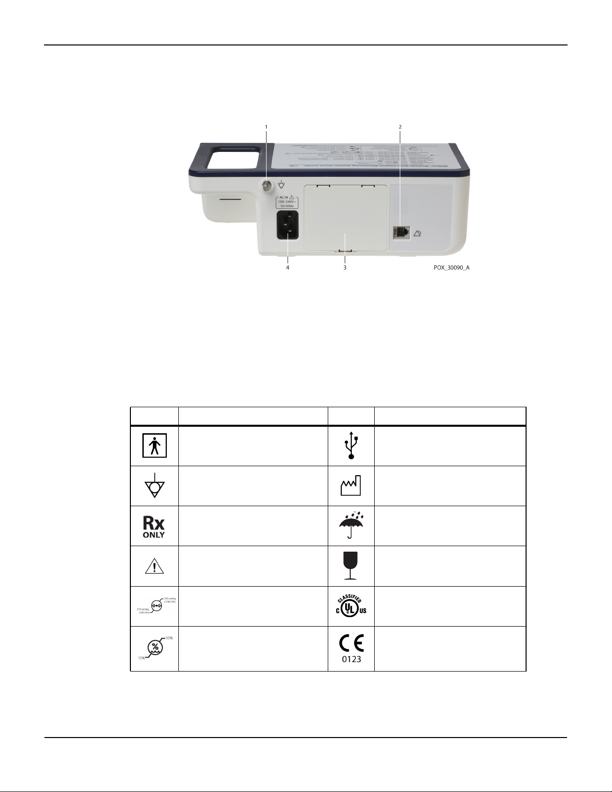
2.4.2 Rear Panel
Product Views
Figure2-3. Rear Panel Components
1 Equipotential terminal 3 Battery cover
2 Nurse call port 4 AC power connector
2.4.3
Product and Carton Label Symbols
Symbol Description Symbol Description
Type BF Data port
Equipotentiality Date of manufacture
Prescription only device Keep dry
Attention, consult accompanying
documents
Atmospheric pressure limitations UL listed
Table2-2.Symbol Descriptors
Fragile
Humidity limitations CE Mark
Operator’s Manual 2-7
Product Overview
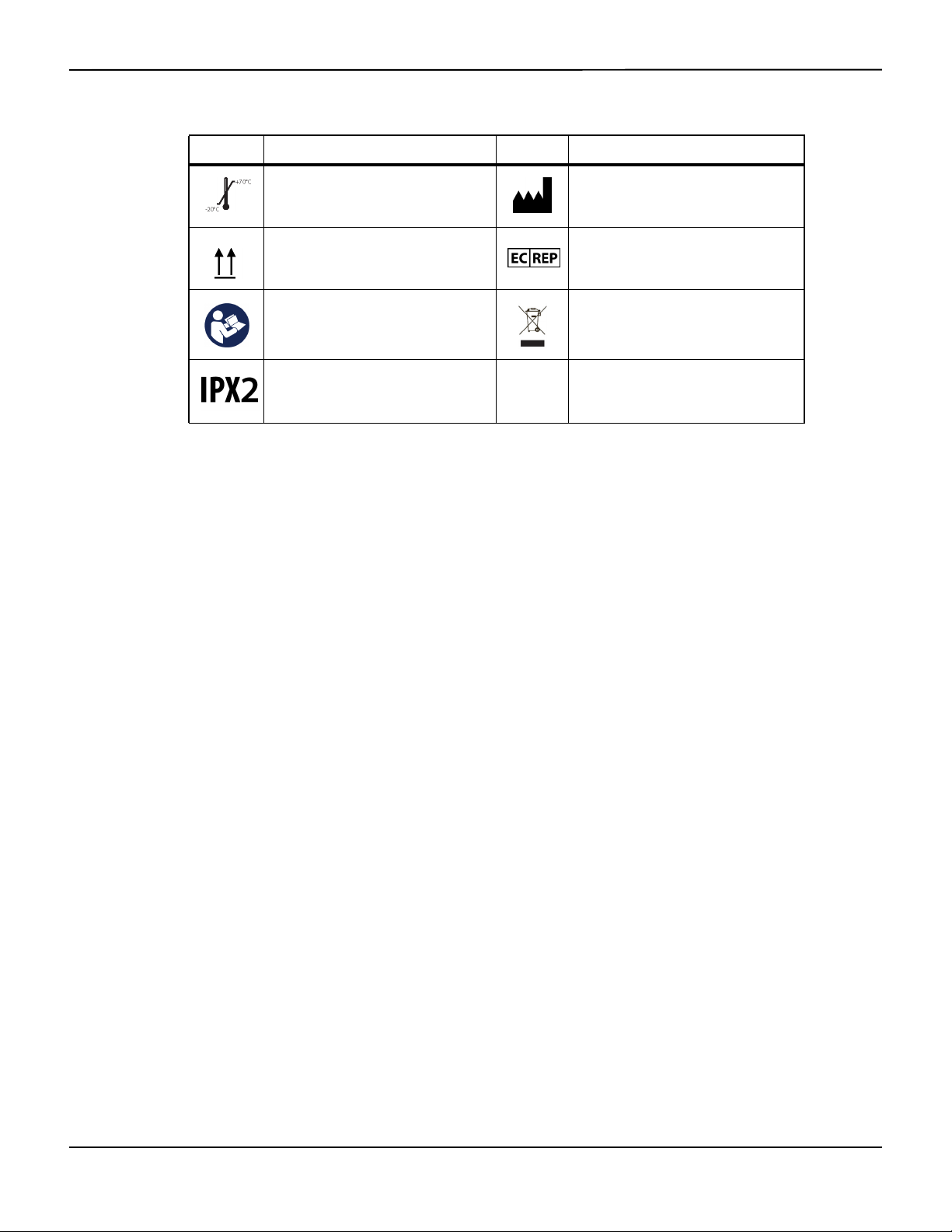
Table2-2.Symbol Descriptors (Continued)
Symbol Description Symbol Description
Temperature limitations Manufacturer
This side up EU representative
Must consult instructions for use
Protection against fluid ingress
Proper waste disposal for electrical and
electronic equipment
2-8 Operator’s Manual

3 Installation
3.1 Overview
This chapter contains information for the installation and set up of the Nellcor™ bedside SpO2
patient monitoring system prior to first-time usage.
3.2 Safety Reminders
WARNING:
Ensure the speaker is clear of any obstruction. Failure to do so could result in an inaudible alarm
tone.
WARNING:
To ensure accurate performance and prevent device failure, do not expose the monitoring
system to extreme moisture, such as direct exposure to rain. Such exposure may cause
inaccurate performance or device failure. Reference Product Specifications, p. 11-1.
WARNING:
The monitoring system should not be used adjacent to or stacked with other equipment. If
adjacent or stacked use is necessary, observe the monitoring system to verify normal operation
in the desired configuration.
WARNING:
Do not use any monitoring system, pulse oximetry sensor, cables, or connectors that appear
damaged.
WARNING:
Use only Nellcor™-approved pulse oximetry sensors and pulse oximetry cables when connecting
to the sensor connector. Connecting any other cable or sensor influences the accuracy of sensor
data, which may lead to adverse results.
WARNING:
Use only the Nellcor™ pulse oximetry interface cable with the monitoring system. Use of another
interface cable will adversely affect performance.
3-1

Installation
Caution:
Follow local government ordinances and recycling instructions regarding disposal or recycling of
device components, including its accessories.
3.3 Unpacking and Inspection
The monitoring system is shipped in a single carton. Examine the carton carefully for evidence of
damage. Contact Covidien Technical Services immediately if the carton appears damaged. Do not
return all packing material and the monitoring system prior to contacting Covidien. Reference
Technical Services, p. 1-5.
Note:
A qualified service technician should verify the performance of the monitoring system following the
procedures outlined in the Nellcor™ bedside SpO
installation in a clinical setting.
The monitoring system ships with a set of standard items, but may also include a number of
optional accessories. Check the shipping carton for all items listed on the packing list.
patient monitoring system Service Manual prior to initial
2
Note:
Contact Covidien Technical Services for pricing and ordering information.
Table3-1.Standard Items
Item Quantity
Nellcor™ bedside SpO
Nellcor™ pulse oximetry interface cable 1
Compact disc (CD) and/or Operator's Manual
Lithium-ion battery pack, M-BPL-1 (21) 5 hour 1
AC power cord 1
1. Covidien provides soft copy of monitoring system manuals on a compact disc for easy access and
print-on-demand. Order a printed Nellcor™ bedside SpO
Manual at no cost or a printed Nellcor™ bedside SpO
fee from Covidien Technical Services or a local Covidien representative.
patient monitoring system 1
2
1
patient monitoring system Operator’s
2
patient monitoring system Service Manual for a
2
1
3-2 Operator’s Manual

Setup
3.4
WARNING:
In the USA, do not connect to an electrical outlet controlled by a wall switch, since this increases
the risk of AC power loss to the monitoring system.
Caution:
The monitoring system must be connected to an appropriate power source.
Caution:
If the integrity of the AC power source is in doubt, ensure the monitoring system internal battery
is fully charged.
3.4.1 Connecting to Power
The monitoring system operates on AC power or on a charged internal battery. Prior to
connecting to power, perform a safety check of the equipment. Reference Periodic Safety Checks,
p. 7-3.
Setup
To connect the AC power cable:
1. Ensure the AC outlet is properly grounded and supplies the specified voltage and frequency (100-
2. Connect the female connector end of the AC power cord to the AC power connector on the
3. Plug the male connector end of the AC power cord into a properly grounded AC outlet.
4. If necessary, connect grounding wire.
5. Ensure the Battery Charge Indicator lights.
Note:
Even if the monitoring system is not turned on, the Battery Charge Indicator lights when the AC power
cord is connected into a mains outlet. Reference Troubleshooting, p. 8-1, if the battery charging indicator
does not light when connected to power.
To troubleshoot an unlit Battery Charge Indicator:
1. Check the power cord.
240V~ 50-60 Hz).
monitoring system's rear panel.
• Connect the grounding wire connector to the rear panel’s equipotential terminal.
• Attach the clip end of the grounding wire to the grounding terminal on the wall.
2. Check the AC power inlet.
Operator’s Manual 3-3

Installation
3. Check the power/ mains outlet.
4. Ensure the internal battery is properly installed and charged.
5. Contact a qualified service technician or a local supplier for assistance.
3.4.2 Using the Internal Battery
WARNING:
The amount of time between the low battery alarm and power off becomes shorter as the battery
accumulates charge/discharge cycles.
Note:
Remove the battery if the monitoring system is not likely to be used for six (6) months.
Note:
Covidien strongly recommends fully recharging the battery whenever the time between recharges
exceeds six (6) months.
Note:
The monitoring system may not operate if the battery charge is critically low.
Note:
Covidien strongly recommends keeping the monitoring system connected to AC power during
continuous operation or to recharge the internal battery.
Note:
Recharging the battery over a period of time may shorten the time between the low battery alarm and power
off. Have a qualified service technician periodically check the internal battery or replace it if necessary.
The monitoring system has an internal battery that powers the monitoring system when AC
power is not available. The monitoring system cannot operate with a fully discharged battery. A
lit battery status icon indicates the monitoring system is running on battery power.
Prior to using the internal battery, perform a safety check of the equipment. Reference Periodic
Safety Checks, p. 7-3.
A new, fully charged optional battery will provide its optimal number of operational hours under
these normal conditions:
• Operating in Normal mode (Measuring SpO
and PR with plethysmograph display)
2
• Setting for pulse beep indicator is ON (pulse volume:4 (Default))
3-4 Operator’s Manual

•
• Experiencing no alarm condition
• Operating at ambient temperature of 25°C (±5°C)
Note:
Two types of battery are available: the standard 5- hour and optional 10-hour.
Note:
Even if the monitoring system is turned off, the Battery Charge Indicator remains lit while the battery
recharges.
Note:
A full charge of a depleted battery takes more than four (4) hours for a 5-hour battery or eight (8) hours for
a 10-hour battery.
Plug the monitoring system into an AC outlet to charge the battery for a minimum of three (3) minutes
prior to turning on any monitoring system with a completely discharged battery. When operating on
internal battery, the monitoring system battery status icon indicates the battery charge condition.
Setup
Setting for SatSeconds™ is ON
To charge the internal battery:
1. Connect the monitoring system to AC power to charge a low or depleted battery. Reference
Connecting to Power, p. 3-3.
2. Verify the Battery Charge Indicator lights.
3.4.3 Connecting a Nellcor™ Pulse Oximetry Sensor
WARNING:
Incorrect application or use of an SpO
too tightly, apply supplemental tape, or leave a sensor too long on one place. Inspect the sensor
site as directed in the Instructions for Use to ensure skin integrity, correct positioning, and adhesion
of the sensor.
sensor can cause tissue damage. Do not wrap the sensor
2
WARNING:
Do not use any other cables to extend the length of the Covidien-approved interface cable.
Increasing the length will degrade signal quality and may lead to inaccurate measurements.
WARNING:
Use only the Covidien-approved pulse oximetry sensor and interface cables. Use of another cable
can have an adverse effect on performance. Do not attach any cable intended for computer use to
the sensor port.
Operator’s Manual 3-5

Installation
WARNING:
Failure to cover the applied pulse oximetry sensor with opaque material while operating under
high ambient light conditions may result in inaccurate measurements.
Caution:
For best product performance and measurement accuracy, use only accessories supplied or
recommended by Covidien. Use accessories according to the Instructions for Use. Use only
accessories that have passed the recommended biocompatibility testing in compliance with
ISO10993-1.
Prior to connecting a sensor, perform a safety check of the equipment. Reference Periodic Safety
Checks, p. 7-3. Reference Nellcor™ Pulse Oximetry Sensors, p. 9-1, for details regarding sensor
selection.
To fully connect a Nellcor™ pulse oximetry sensor:
1.
Select an appropriate compatible Nellcor™ pulse oximetry sensor for the patient and desired application. When
selecting a sensor, consider the patient's weight and activity, adequacy of perfusion, availability of sensor sites,
need for sterility, and anticipated duration of monitoring.
2. Carefully apply the sensor to the patient after reading the Instructions for Use accompanying the sensor.
3. Connect the interface cable to the sensor port on the front of the panel and firmly connect the
A Sensor Message occurs when the device cannot obtain an SpO2 level or a pulse rate.
Note:
If the sensor is not connected firmly, the monitoring system could lose signal from patient.
Note:
Physiological conditions, medical procedures, or external agents that may interfere with the monitoring
system’s ability to detect and display measurements include dysfunctional hemoglobin, arterial dyes, low
perfusion, dark pigment, and externally applied coloring agents, such as nail polish, dye, or pigmented
cream.
Observe all warnings and cautions in the Instructions for Use.
interface cable to the pulse oximetry sensor. When the monitoring system detects a valid pulse, it
enters monitoring mode and displays real-time patient data.
Figure3-1.Connecting a Pulse Oximetry Sensor to Interface Cable
3-6 Operator’s Manual

4 Operation
4.1 Overview
This chapter identifies methods for viewing and collecting patient oxygen saturation data using
the Nellcor™ bedside SpO
thoroughly read this manual.
4.2 Safety Reminders
WARNING:
The monitoring system is intended only as an adjunct in patient assessment. It must be used in
conjunction with clinical signs and symptoms.
WARNING:
Tissue damage can be caused by incorrect application or use of a pulse oximetry sensor. Do not
wrap the pulse oximetry sensor too tightly, apply supplemental tape, or leave it too long on one
place. Inspect the pulse oximetry sensor site as directed in the Instructions for Use to ensure skin
integrity, correct positioning, and adhesion.
patient monitoring system. Before operating the monitoring system,
2
WARNING:
Keep patients under close surveillance when monitoring. It is possible, although unlikely, that
radiated electromagnetic signals from sources external to the patient and the monitoring
system can cause inaccurate measurement readings. Do not rely entirely on the monitoring
system's readings for patient assessment. This device has been tested and found to comply with
the limits for medical devices related to IEC 60601-1-2: 2007 and IEC 60601-1-2:2014. These
limits are designed to provide reasonable protection against harmful interference in a typical
medical installation.
WARNING:
For best product performance and measurement accuracy, use only accessories supplied or
recommended by Covidien. Use accessories according to their respective Instructions for Use.
4-1

Operation
WARNING:
Do not use damaged pulse oximetry sensors. Do not use with exposed optical components. Do not
immerse completely in water, solvents, or cleaning solutions, since pulse oximetry sensors and
connectors are not waterproof. Do not sterilize by irradiation, steam or ethylene oxide. Refer to the
cleaning instructions in the Instructions for Use for reusable sensors.
Caution:
Do not attach any cable intended for computer use to the sensor port connector.
Caution:
The sensor disconnect error message and associated alarm indicate the pulse oximetry sensor is
either disconnected or has faulty wiring. Check the connection and, if necessary, replace it, the
pulse oximetry cable, or both.
4.3 User Interface
4.3.1 Turning on the Monitoring System
WARNING:
Ensure the speaker is clear of any obstruction. Failure to do so may result in an inaudible tone.
Caution:
If any indicator or display element does not light, or the speaker does not sound, do not use the
monitoring system. Instead, contact a qualified service technician.
Before using the monitoring system in a clinical setting, ensure the monitoring system is working
properly and is safe to use.
When the monitoring system completes power-on self-test (POST), a POST pass tone sounds. This functions
as an audible confirmation of proper speaker performance. If the speaker does not function, the alarm
warning sounds remain inaudible.
Note:
Pressing any button should result in either a valid or an invalid tone. If a button press fails to emit a tone,
contact a qualified service technician.
To power on the monitoring system:
1. Press the Power On/Off Button for more than one (1) second.
2. Ensure the software version, the SpO
approximately two (2) seconds.
4-2 Operator’s Manual
alarm indicator, and the pulse rate alarm indicator light for
2

3. Ensure the POST pass tone sounds when POST completes.
Note:
Do not use the monitoring system should a repeating, high-pitched alarm tone occur at power on. Instead,
please contact Technical Services or a qualified service technician.
Menu Options Navigation
Figure4-1.Sample Initial Screen
4.3.2 Turning off the Monitoring System
After using the monitoring system, turn it off safely.
To turn off the monitoring system:
1.
Press the Power On/Off button on the right of the device for approximately one second.
2. Observe the message System is shutting down on the screen.
Note:
Press the Power On/Off button for at least 15 seconds to turn off the monitoring system after any situation
involving continuous resets or a system lock.
4.4 Menu Options Navigation
Navigating menu options on the monitoring system requires manual manipulation of the three
buttons and the jog dial.
Press the desired interface button.
1. Power On/Off button — Press and hold this blue button to power on or to power off the monitoring
system. This button illuminates at power on and remains lit until power off.
2. Return button — Press this green button for less than two (2) seconds to exit menu items and return
to the main monitoring screen. This button illuminates at power on and remains lit until power off.
Operator’s Manual 4-3

Operation
Note:
3. Silence Alarm button — Press this orange button for less than two (2) seconds to disable or re-
enable audible alarms. This button illuminates at power on and remains lit until power off.
Rotate or press the jog dial to navigate among various portions of the screen and to select menu
items.
If a user presses and holds the RETURN button while accessing a menu item, but before saving any changes,
the monitoring system requires the user to confirm a cancellation of all pending changes. A user prompt
appears and the user must either save all pending changes (save new value) or cancel all pending changes
(return to previous value) before taking any other action.
Figure4-2.Save Change Screen
1. Navigation — Rotate the jog dial clockwise or counter-clockwise until a colored highlight surrounds
the desired area. Any rotation of the jog dial either navigates or changes the desired option setting.
2. Selection — Press the jog dial to select that desired area, then continue rotating the jog dial until
highlighting the desired menu option, then press again.
The LCD display panel also users with easy-to-read numeric values for patient oxygen saturation
and pulse rate in cyan and yellow, respectively. Reference Table2-1. on page 2-6.
4-4 Operator’s Manual

4.4.1 Menu Structure
Item Available selections Default
Menu Options Navigation
Table4-1.Menu Structure and Available Options
QUICK ACCESS ALARM LIMITS menus
SpO
menu SatSeconds™ alarm management setting (Off, 10, 25, 50, 100)
2
100
Upper (21-100) SpO
Lower (20-99) SpO
Alarm Inhibition for SpO
PULSE RATE (PR) menu Upper (30-245) pulse rate alarm limit
alarm limit
2
alarm limit
2
alarms
2
Depends on
patient mode.
Reference
Table4-4. on
page 4-17
Lower (25-240) pulse rate alarm limit
Alarm Inhibition for pulse rate alarms
OPTIONS menu
VOLUME Alarm Volume (1-8) 5
Key Beep Volume (Off, 1-7) 4
Pulse Volume (Off, 1-7) 4
MODE (response mode) Normal, Fast Normal
TREND DATA DOWNLOAD Start (Cancel or Return), Return --
DELETE ALL TREND DATA No, Yes --
SERVICE MENU (For qualified service technicians only) --
ALARM/LIMITS menu
SpO
LIMITS options Upper (21-100) SpO2 alarm limit
2
Lower (20-99) SpO
Alarm Inhibition for SpO
alarm limit
2
alarms
2
PULSE RATE LIMITS options Upper (30-245) pulse rate alarm limit
Lower (25-240) pulse rate alarm limit
Depends on
patient mode.
Reference
Table4-4. on
page 4-17.
Alarm Inhibition for pulse rate alarms
SATSECONDS option SatSeconds™ alarm management setting
100
(Off, 10, 25, 50, 100)
PATIENT MODE menu
ADULT option Sets alarm limits to standard default thresholds for adult patients
Reference
PEDIATRIC option Sets alarm limits to standard default thresholds for pediatric patients
Table4-4. on
page 4-17.
NEONATE option Sets alarm limits to standard default thresholds for neonate patients
SpO
WAVEFORM menu
2
SWEEP SPEED option 6.25 mm/s, 12.5 mm/s, 25.0 mm/s 25.0 mm/s
TABULAR TREND option Tabular trend view of trend data
--
GRAPHICAL TREND option Graphical trend view of trend data
Operator’s Manual 4-5

Operation
4.4.2 QUICK ACCESS Menus
For quick access to alarm limit settings, use the menu options listed here.
1. SpO
Menu — Provides access to SpO2 alarm limit settings, alarm inhibition, and SatSeconds™ alarm
2
management option. Reference ALARM/LIMITS Menu, p. 4-10, for basic information. The adult default
setting for the SatSeconds™ alarm management option is 100. Other options include OFF, 10, 25, and
50. Reference SatSeconds™ Alarm Management Feature, p. 10-5.
Figure4-3.QUICK ACCESS SpO2 Menu with Audio Alarm Selected
2. PR Menu — Provides access to pulse rate (PR) alarm limit settings and alarm inhibition. Reference
ALARM/LIMITS Menu, p. 4-10.
Figure4-4.QUICK ACCESS PR Menu with Alarm Audio OFF
To select alarm limit settings via Quick Access menus:
1. Rotate the jog dial until the white highlight appears over the SpO
or the pulse rate (PR) real-time value
2
field.
2. Press the jog dial.
4-6 Operator’s Manual

3. Rotate the jog dial until reaching the desired field.
Menu Options Navigation
• Available SpO
– SatSeconds™ alarm management values include OFF, 10, 25, 50, 100. The default value is 100. Reference
alarm limit thresholds
2
SatSeconds™ Alarm Management Feature, p. 10-5.
– Upper and lower SpO
– SpO
• Pulse Rate alarm limits
– Upper and lower pulse rate alarm limit thresholds
– Pulse rate alarm inhibition to disable audible alarms for pulse rate limit violations
4. Press the jog dial to select the field.
5. Rotate the jog dial to change the field.
6. Exit the menu using either of the listed strategies.
• Rotate the jog dial to highlight the Return option and press the jog dial.
• Press the Return button until the LCD returns to its original screen.
alarm inhibition to disable audible alarms for SpO2 limit violations
2
alarm limit thresholds
2
4.4.3 OPTIONS Menu
Caregivers may choose from Volume, Mode, or Trend Data menu options.
To access the OPTIONS Menu:
1. Rotate the jog dial to highlight the OPTIONS Menu icon.
2. Press the jog dial to access the OPTIONS Menu.
Volume
Access this menu option to adjust volume controls.
To set the desired audible tone volume:
1. Access the OPTIONS Menu.
2. Rotate the jog dial to highlight VOLUME.
Operator’s Manual 4-7

Operation
Figure4-5.Volume Selection
3. Press the jog dial to access Alarm Volume, Key Beep Volume, or Pulse Volume.
• Alarm Volume controls the volume (1-8) of alarms.
• Key Beep Volume controls the volume (0ff, 1-7) of any button press.
• Pulse Volume controls the volume (0ff, 1-7) of the plethysmographic waveform.
4. Rotate the jog dial to select the desired volume level.
5. Press the jog dial to save the desired volume level.
Figure4-6.Volume Selection
Mode (Response Mode)
The response mode (Normal or Fast) establishes the rate at which the monitoring system
responds to changes in the SpO2 data.The calculation of pulse rate and the recording of trend
data are not affected. The response mode setting does not affect the algorithm’s calculation of
4-8 Operator’s Manual

Menu Options Navigation
pulse rate, nor does it influence the recording of trend data which occurs at one-second intervals.
The default setting is the Normal Response Mode.
To set response mode:
1. Access the OPTIONS Menu.
2. Rotate the jog dial to highlight MODE.
3. Press the jog dial to select Normal or Fast response mode.
• Normal response mode — Responds to changes in blood oxygen saturation within five (5) to
seven (7) seconds.
• Fast response mode — Responds to changes in blood oxygen saturation within two (2) to four
(4) seconds. This mode can be particularly helpful for situations that require close monitoring.
Figure4-7.Response Mode Menu
Note:
When in the Fast Response Mode, the monitoring system may produce more SpO
than expected.
Trend Data Download
Access this menu option to download patient trend data. Reference Trend Data Download, p. 5-5.
Delete All Trend Data
Access this menu option to delete all patient trend data from memory.
To delete all trend data:
1. Access the OPTIONS Menu.
2. Rotate the jog dial to highlight DELETE ALL TREND DATA.
Operator’s Manual 4-9
and pulse rate alarms
2

Operation
Figure4-8.Delete All Trend Data Menu Item
3. At the prompt “Are you sure you want to delete all trend data?” choose one of the following options.
• Press the jog dial to select NO and keep all trend data.
• Rotate the jog dial to select YES, then press to delete all trend data.
• Rotate the jog dial to select RETURN, then press to access the OPTIONS menu.
Service Menu
Only a qualified service technician may change Service Menu settings. A pass code is required for
access. Refer to the Service Manual for instructions.
4.4.4 ALARM/LIMITS Menu
WARNING:
Do not silence the audible alarm or decrease its volume if patient safety could be compromised.
WARNING:
Prior to each use of the monitoring system, check the alarm limits to ensure they are appropriate
for the patient being monitored. Ensure alarm limits do not exceed the standard thresholds set by
the institution.
WARNING:
Do not preset different alarm limits for the same or similar equipment within a single area.
Caregivers may choose to adjust SpO2 and pulse rate (PR) alarm thresholds from default values as
necessary. These changes remain in effect until modified again or until a power cycle occurs.
4-10 Operator’s Manual

Menu Options Navigation
Changes to the SpO2 and pulse rate (PR) alarm thresholds appear in their respective numerical
area. In addition, caregivers may choose to use the SatSeconds™ alarm option to manage the
frequency of SpO
alarm limit violations by adjusting the SatSeconds™ setting. The higher the
2
value, the less frequent the alarm.
SpO2 numerical area — Indicates hemoglobin oxygen saturation levels. The display value flashes
zeros during loss-of-pulse alarms and flashes the SpO
is outside the alarm limits. During pulse searches, the monitoring system continues to update the
display. Current upper and lower alarm limit settings appear as smaller values to the left of the dynamic
value. Reference Factory Defaults, p. 4-17, for default alarm limit settings.
SpO
2
Pulse Rate (PR) numerical area — Displays the pulse rate in beats per minute (bpm). The display
value flashes zeros during loss-of-pulse alarms and flashes the pulse rate value on a yellow background
when the pulse rate is outside of the alarm limits. During Pulse Search, the monitoring system
continues to update the display. Pulse rates outside of the pulse rate range of 20 to 250 bpm are
displayed as 0 and 250, respectively. Current upper and lower alarm limit settings appear as smaller
values to the left of the dynamic pulse rate value. Reference Factory Defaults, p. 4-17, for default alarm
limit settings.
To set alarm limits:
1. Rotate the jog dial to highlight the ALARM LIMITS icon.
value on a yellow background when saturation
2
2. Press the jog dial to display the ALARM/LIMITS Menu.
• Alarm Limits include pulse rate (PR) and SpO
• The SatSeconds™ Alarm option provides alarm management of SpO
• The alarm inhibit icon provides caregivers with the option of inhibiting the alarm for SpO
alarm limit ranges.
2
alarm limit violations.
2
pulse rate alarms.
3.
Rotate the jog dial to highlight the desired option.
4.
Press the jog dial to select the desired option.
Figure4-9.Alarm/Limits Menu Options
and/or
2
Operator’s Manual 4-11

Operation
5.
Rotate the jog dial to change the desired option value. Reference Menu Structure, p. 4-5, for adult, pediatric,
and neonate limit options.
• Available SpO
– Upper and lower SpO
– SpO
• Pulse Rate alarm limits
– Upper and lower pulse rate alarm limit thresholds
– Pulse rate alarm inhibition to disable audible alarms for pulse rate limit violations
• SatSeconds™ alarm management values include OFF, 10, 25, 50, 100. The default value is 100.
alarm limit thresholds
2
alarm limit thresholds
2
alarm inhibition to disable audible alarms for SpO2 limit violations
2
Reference SatSeconds™ Alarm Management Feature, p. 10-5.
6.
Press the jog dial to save the desired value.
7.
Rotate the jog dial to highlight another desired option or to RETURN to the OPTIONS menu.
4.4.5 PATIENT MODE Menu
Access this menu option to select the desired PATIENT MODE: Adult, Pediatric or Neonatal.
To set patient mode:
1. Rotate the jog dial to highlight the Patient Mode icon.
2. Press the jog dial to display PATIENT MODE.
Figure4-10.Patient Mode Menu
3. Rotate the jog dial to highlight the desired mode option: Adult, Pediatric or Neonatal. Use the
appropriate patient mode and pulse oximetry sensor based on body weight. Reference the pulse
oximetry sensor Instructions for Use.
4-12 Operator’s Manual

Adult: Use for adults.
Pediatric: Use for children.
Neonatal: Use for newborns.
4. Press the jog dial to save the desired mode.
5. Press the RETURN button to exit PATIENT MODE.
Menu Options Navigation
4.4.6 SpO
WAVEFORM Menu
2
Caregivers may choose to set sweep speed of the plethysmographic waveform and opt to view
the tabular or graphical trend screen.
To access the WAVEFORM Menu:
1. Rotate the jog dial to highlight the waveform display area.
Figure4-11.Highlighting the Waveform Display Area
2. Press the jog dial to display the SpO
Operator’s Manual 4-13
WAVEFORM Menu.
2
Figure4-12.SpO2 Waveform Menu

Operation
Sweep Speed — Access to set the speed at which the SpO2 waveform trace moves across the
•
screen. The higher the sweep speed value, the more data appears on the screen. Sweep Speed
options are 6.25 mm/s, 12.5 mm/s and 25.0 mm/s.
• Tabular Trend — Access to display the tabular trend view. Reference Tabular Trend Data, p. 5-1.
• Graphical Trend — Access to display the graphical trend view. Reference Graphical Trend Data, p.
5-2.
4.5 Managing Alarms and Alarm Limits
WARNING:
Setting alarm limits to off or extreme high or low values will reduce alarm efficacy.
WARNING:
Do not silence the audible alarm or decrease its volume if patient safety could be compromised.
WARNING:
Prior to each use of the monitoring system, check the alarm limits to ensure they are appropriate
for the patient being monitored. Ensure alarm limits do not exceed the standard thresholds set by
the institution.
WARNING:
Ensure the speaker is clear of any obstruction. Failure to do so could result in an inaudible alarm
tone.
When the monitoring system detects certain conditions that require user attention, the
monitoring system enters an alarm state.
The monitoring system uses both visual and audible indicators to identify high-priority, mediumpriority, and low-priority alarms. Audible alarms include pitched tones, beeps, and a buzzing tone.
High priority alarms take precedence over medium- and low-priority alarms. Reference
Troubleshooting, p. 8-1.
4-14 Operator’s Manual

Managing Alarms and Alarm Limits
Table4-2.Alarm Conditions
Priority Rate Color Messages
High Sounds every 4 s Red
Steady message,
Fast flashing numeric
Medium Sounds every 8 s Yellow
Steady message,
Slow flashing numeric
Low Sounds every 16 s Steady yellow SpO
Informative -- -- SpO
SpO
Critically Low-Battery condition
High Pulse Rate limits violated
Low Pulse Rate limits violated
High SpO
Low SpO
SpO
Low Battery
Technical System Error: EEE 001
Signal Artifact Detected
Abnormally shut down last time
Audio OFF, Alarm Silenced
Press Return Button to Exit...
Loss of Pulse
2
limits violated
2
limits violated
2
Cable/Sensor Disconnect
2
Sensor Off
2
Pulse search
2
Note:
The audible and visual alarms on the monitoring system, used in conjunction with clinical signs and
symptoms, are the primary source for notifying medical personnel that a patient alarm condition exists.
Note:
If the monitoring system fails to perform as specified, contact Covidien Technical Services, a qualified
service technician, or a local supplier for assistance.
4.5.1 Audible Alarm Indicators
WARNING:
Do not silence the audible alarm or decrease its volume if patient safety could be compromised.
WARNING:
Pressing the Silence Alarm button will silence all audible alarms except "Battery Critically Low."
Audible alarm indicators include pitched tones and beeps. Caregivers may choose to silence the
audible alarm for the established Alarm Silence period of 30, 60, 90 or 120 seconds. Visual alarms
continue during this time. The factory default for audible alarm silence period is 60 seconds. To
Operator’s Manual 4-15

Operation
Note:
set one of the listed alternate periods as an institutional default, have a qualified service technician
set the desired period via the SERVICE Menu.
Alarm delays should not exceed 10 seconds other than as specified in this manual.
Table4-3.Audio Status
Alarm icon Status
Alarm Silenced
Audio OFF
To silence an audible alarm:
1. Press the Silence Alarm button to immediately silence the alarm tone. The alarm resumes after the
Alarm Silence period, if the alarm condition remains.
2. Take the appropriate corrective action.
Note:
Press the Silence Alarm button to silence audible alarms caused by technical errors. Audible alarms for
physiological conditions can be silenced. However, they require appropriate corrective action. Press the
Silence Alarm button to dismiss an SpO
To re-enable the audio tones during the Alarm Silence period, press the Silence Alarm button
again.
To silence an audible alarm:
1. Press the Silence Alarm button.
2. To re-enable, press the Silence Alarm button again.
If the Alarm Silence period is enabled, the audible alarm is not active for the specified time
interval and the Alarm Silenced icon appears above the appropriate alarm limit icon. A
countdown timer indicates any silence time remaining.
Note:
To disable limit violation alarms, use the Alarm Limits menus. Reference ALARM/LIMITS Menu, p. 4-10.
Sensor Off alarm or SpO2 Cable/Sensor Disconnect alarm.
2
4.5.2 Visual Alarm Indicators
Visual alarms appear on the screen in order of highest priority, regardless of any audible alarm
status. Reference Table4-2. on page 4-15.
4-16 Operator’s Manual

Factory Defaults
Factory Defaults
4.6
The monitoring system ships with factory default settings. To set different institutional default
settings, contact a qualified service technician.
Table4-4. Parameter Ranges and Factory Defaults
Parameter Ranges/selection Factory default
Adult Pediatric Neonatal
SpO
2
%SpO2 upper alarm limit 21 to 100% (1% steps) 100%
%SpO
lower alarm limit 20 to 99% (1% steps) 90% 85%
2
%SpO
limit alarm inhibition On, Off Off
2
SatSeconds™ alarm Off, 10, 25, 50, 100 100
Pulse rate
Pulse rate upper alarm limit 30 to 245 bpm (5 bpm steps) 170 bpm 200 bpm
Pulse rate lower alarm limit 25 to 240 bpm (5 bpm steps) 50 bpm 75 bpm 100 bpm
PR limit alarm inhibition On, Off Off
Tabular trends
Scroll 1, 5, 100, 500 1
Graphical trends
SpO
2
PR On, Off On
Patient mode Adult, Pediatric, Neonatal Adult
On, Off On
Others
95%
Alarm volume 1, 2, 3, 4, 5, 6, 7, 8 5
Key beep volume Off, 1, 2, 3, 4, 5, 6, 7 4
Pulse volume Off, 1, 2, 3, 4, 5, 6, 7 4
Date/time settings
Alarm silence duration
Alarm disabled reminder
Mode (response mode) Normal, Fast Normal
Operator’s Manual 4-17
1
1
1
yy/mm/dd, mm/dd/yy, dd/mm/yy yy/mm/dd
30, 60, 90, 120 s 60 s
OFF, 3, 10 min 3 min

Operation
Parameter Ranges/selection Factory default
Trend data download settings
Table4-4. Parameter Ranges and Factory Defaults (Continued)
Adult Pediatric Neonatal
1
Baud rates: 19200, 38400, 57600, 115200 bps 19200 bps
Protocol: ASCII 1, ASCII 2 ASCII 1
Nurse call settings: NORMALLY +,
NORMALLY –
Sweep speed 6.25, 12.5, 25.0 mm/s 25.0 mm/s
Power on settings
Language
1. To alter this parameter, a qualified service technician must access the Service Menu, as described in the S ervice Manual.
Maintenance Reminder
4.7
1
1
Factory Defaults, Last Settings, Institutional
Defaults
Chinese, Czech, Danish, Dutch, English,
Finnish, French, German, Greek, Italian,
Japanese, Korean, Norwegian, Polish,
Portuguese, Russian, Slovakian, Spanish,
Swedish, Turkish
NORMALLY –
Factory Defaults
English
Schedule regular maintenance and safety checks with a qualified service technician every 24
months. Reference Periodic Safety Checks, p. 7-3. In the case of mechanical or functional damage,
contact Covidien or a local Covidien representative. Reference Obtaining Technical Assistance, p.
1-5.
4-18 Operator’s Manual

5 Data Management
5.1 Overview
This chapter contains information for accessing patient trend data obtained using the Nellcor™
bedside SpO
stored in the monitoring system.
The monitoring system stores up to 96 hours of trend data. When the monitoring system begins
measuring vital signs, it saves data every four (4) seconds. It also saves all physiological alarm
conditions and errors. Trend data history remains in memory even if the monitoring system is
powered off. The monitoring system stores new data over the oldest data when the buffer is full.
5.2 Tabular Trend Data
The monitoring system presents trend information in tabular format for all monitored
parameters when users enable this option. The newest data values appear at the top.
patient monitoring system. Trend data can be viewed anytime patient trend is
2
Figure5-1.Tabular Trend Data Screen
To select Tabular Trend:
1. Rotate the jog dial to highlight the waveform area.
2. Press the jog dial to display the SpO
WAVEFORM Menu.
2
5-1

Data Management
3. Select Tabular Trend.
To scroll through Tabular Trend Data:
1. Rotate the jog dial to scroll through the trend data.
• Clockwise rotation moves forward to newer data.
• Counterclockwise rotation moves backward to older data.
2. Press the jog dial again to adjust the scroll granularity. Larger values scroll through more data faster.
Note:
To scroll most efficiently, adjust the scroll granularity more than once. For instance, use the +/-500 to
scroll quickly to the desired time stamp, then press the jog dial again to reach the +/-1 to scroll through
each individual event in that time period.
3. After reviewing trend data, press the RETURN button to exit the tabular trend view.
5.3 Graphical Trend Data
The monitoring system presents trend information in a single graph for all monitored parameters
when users enable this option. The vertical range of a graphical trend appears as a fixed value. The
horizontal range is 24 minutes. The newest data values appear to the right.
To select Graphical Trend:
1. Rotate the jog dial to highlight the waveform area.
2. Press the jog dial to display the SpO
3. Select Graphical Trend.
Waveform Menu.
2
Figure5-2.Graphical Trend Data Screen
5-2 Operator’s Manual

To scroll through Graphical Trend Data:
1. Rotate the jog dial to highlight Scroll.
2. Press the jog dial to activate scrolling.
3. Rotate the jog dial to scroll through the trend data.
• Clockwise rotation moves forward to newer data.
• Counterclockwise rotation moves backward to older data.
4. After reviewing trend data, press the RETURN button to exit the graphical trend view.
5.4 External Data Communication
WARNING:
Any connections between this monitoring system and other devices must comply with applicable
medical systems safety standards such as IEC 60601-1. Failure to do so may result in unsafe
leakage current and grounding conditions.
External Data Communication
The monitoring system provides external connectors on the right and rear panels to support data
communication.
• Nurse call interface (RJ11) — Allows caregivers to remotely monitor patient alarms via the nurse call
system of the institution.
• USB interface — Enables firmware upgrades. Reference the Service Manual.
• Mini USB interface — Enables trend data downloads and connection to a personal computer (PC).
5.4.1 Nurse Call Interface
WARNING:
Do not use the nurse call feature as the primary source of alarm notification. The audible and visual
alarms of the monitoring system, used in conjunction with clinical signs and symptoms, are the
primary sources for notifying medical personnel that an alarm condition exists.
WARNING:
The nurse call feature does not function when monitoring system alarms are silenced.
Caution:
Test the nurse call function prior to use, especially when setting up the monitoring system in a new
location. One way to test the nurse call function is to create an alarm condition (for example,
sensor disconnect) and verify the nurse call system properly activates.
Operator’s Manual 5-3

Data Management
Note:
Communication (Nurse Call Interface) is limited to inside a single institution.
The nurse call feature of the monitoring system works in conjunction with the nurse call system
of the institution when the monitoring system sounds an audible alarm. It is operational
regardless of whether the monitoring system uses AC power or battery power, as long as a proper
connection between the nurse call port and the host system exists.
Figure5-3.Nurse Call Interface Pin Layout
To connect the nurse call cable:
1. Grasp the RJ11 end of the cable.
2. Firmly insert into the nurse call port.
3. Attach the alternate end of the cable into the host system.
To disconnect the nurse call cable:
1. Grasp the RJ11 end of the cable and press down on the plastic tab on the cable’s connector.
Do not attempt to remove the connector without pressing down on the tab.
2. Gently pull the RJ11 connector out of the nurse call port.
The nurse call feature uses a relay closure to signal the nurse station during alarm conditions. The
nurse call polarity can be set to NORMALLY + or NORMALLY –. A qualified service technician can
set the nurse call polarity using the procedure described in the Service Manual.
When the nurse call polarity is set to NORMALLY +, the nurse call relay operation is as follows:
5-4 Operator’s Manual

Table5-1.Nurse Call Relay Pins States for NORMALLY +
External Data Communication
Monitoring system ON Monitoring system OFF
NORMALLY + No alarm
or alarm silenced
Pin 1 and Pin 2 Open Closed Closed
Pin 2 and Pin 3 Closed Open Open
Audible alarm
When the nurse call polarity is set to NORMALLY –, the nurse call relay operation is as follows:
Table5-2.Nurse Call Relay Pins States for NORMALLY –
Monitoring system ON Monitoring system OFF
NORMALLY – No alarm
or alarm silenced
Pin 1 and Pin 2 Closed Open Closed
Pin 2 and Pin 3 Open Closed Open
Audible alarm
Pin 2 is a common lead for both relays.
5.4.2 Trend Data Download
Caution:
Anyone who connects a PC to the data output port configures a medical system and is therefore
responsible for ensuring that the system complies with the requirements of IEC Standard 606011-1 and the electromagnetic compatibility IEC Standard 60601-1-2.
Caution:
Signal artifacts, secondary to a variety of external factors, may compromise the presence or
accuracy of the displayed values.
Connect the mini-USB port to a PC for downloading trend data. Any PC connected to the data
port must be certified according to IEC Standard 60950. All combinations of equipment must be
in compliance with IEC Standard 60601-1-1 system requirements. Use either ASCII
communication protocol.
• Nellcor™ ASCII protocol (ASCII 1)
• ASCII format compatible with several spreadsheet programs (ASCII 2)
Operator’s Manual 5-5

Data Management
Note:
Users may choose to import patient trend data to a spreadsheet program. To do so, users must export
trend data using the ASCII 2 format option. Have a qualified service technician set this option prior to
attempting a data download.
System Compatibility Prerequisites
• Windows™* Vista/XP/Server 2003/2000
• Pentium™* 100 MHz CPU
• 256 MB RAM
• HyperTerminal™* or equivalent software
Hardware
• Mini-USB data download cable
• CD, if USB driver required
The COM port on the side of the monitoring system provides access to collected trend data. Data
transfer relies on existing communication software drivers for USB-based devices already on the
computer, so should not require any modification of the drivers used by the USB interface. If, for
some reason, the computer does not have the correct USB driver, use the device driver provided
on the product CD or from Technical Services. Reference COM port USB Driver Alternatives, p. 5-10.
Note:
Any trend data download relies on either factory default settings or institutional default settings
established by a qualified service technician prior to usage. This includes baud rate and communication
protocol selection.
To download trend data
1. Power on the monitoring system by pressing the button.
2. Rotate the jog dial to highlight the OPTIONS Menu icon.
3. Press the jog dial to access the OPTIONS Menu.
4. Rotate the jog dial to select the TREND DATA DOWNLOAD submenu option.
5-6 Operator’s Manual

Figure5-4.Trend Data Download Option
5. Press the jog dial to access the TREND DATA DOWNLOAD Menu.
6. Connect a mini-USB cable from the monitoring system to the computer.
External Data Communication
a. Grasp the mini-USB end of the cable.
b. Firmly insert into the bottom mini-USB data port.
c. Firmly insert the USB end of the cable into a USB port on the host system.
7.
Ensure the computer properly identifies the monitoring system. If it does not, follow the procedure for
loading the appropriate driver. Reference To install a USB driver from the compact disc, p. 5-11.
8. Launch HyperTerminal™*. Reference p. 5-8.
9. Press the jog dial again, since the item highlighted is the START option.The status bar indicating total
percentage of the download appears and the START option, immediately changes to a CANCEL
option.
Note:
Users may choose to cancel the download operation at any point in the download process by
selecting CANCEL and then RETURN.
Operator’s Manual 5-7

Data Management
10. Confirm the monitoring system is sending trend data to a personal computer (PC) by observing the
computer screen for a scrolling trend data record. If no trend data values appear, check connectivity
and ensure the personal computer contains HyperTerminal™* software. If this is all operational, verify
patient trend data history exists on the monitoring system. Contact Technical Services or a qualified
service technician for assistance.
Figure5-5.Trend Data Download Status
11. Wait for the OUTPUT COMPLETE message to indicate the download is complete.
12. Save patient trend data to the personal computer disk or to an alternate source, depending on
institutional requirements.
To launch HyperTerminal™*:
1. Click the START menu in the main task bar.
2. Mouse over the PROGRAMS submenu, then ACCESSORIES, then COMMUNICATIONS, then the
HYPERTERMINAL option.
Note:
If this is the first time the HyperTerminal™* program launches, it will prompt the user to set it as the
default Telnet program. Depending on institutional requirements, users may choose YES or NO.
3. Click the HYPERTERMINAL option.
4. When the Connect Description window opens, type in the desired file name in the Name field.
5. Locate the proper icon by scrolling all the way to the far right of the icon field.
6. Select the icon.
7. Click the OK button.
5-8 Operator’s Manual

Note:
If the personal computer is not connected via the USB to mini-USB cable to the monitoring system, the
proper COM port option will not appear in the list.
8. When the Connect To window opens, find the CONNECT USING option and click the down arrow to
identify possible modem options.
9. Select the desired COM port.
10. Click the OK button.
11. In the COM PROPERTIES window, set the appropriate values.
a. Set the baud rate (bits per second) to match the monitoring system. The factory default baud rate
b. Ensure the data bit is set to 8.
c. Ensure the parity bit is set to none.
d. Ensure the stop bit is set to 1.
External Data Communication
is 19200 bits per second (bps).
e. Ensure the flow control is set to none.
12. Click the OK button.
Note:
To test for trend data download connectivity, proceed with the download by pressing the START
option. If no data values appear in HyperTerminal™*, try a different COM port, select the FILE menu,
click NEW CONNECTION, and select a different COM port until data values scroll across the
HyperTerminal™* screen.
To interpret downloaded trend data:
1. Examine trend data on the HyperTerminal™* screen, in a spreadsheet, or on a printout from the
personal computer.
Table5-3.Operating Status Codes
Code Definition Code Definition
AO Alarm off PH Pulse rate upper limit alarm
AS Alarm silence PL Pulse rate lower limit alarm
BU Battery in use PS Pulse search
LB Low battery SD Sensor disconnect
LM Loss of pulse with signal artifact SH Saturation rate upper limit alarm
LP Loss of pulse SL Saturation rate lower limit alarm
ID Signal artifact detected SO Sensor off
MO Signal artifact
Operator’s Manual 5-9

Data Management
Figure5-6.Sample Trend Data Printout
1 Product column headings Data source, firmware version, and system settings
2 Patient data column headings Lists appropriate time and data headings
3 Time column Real-time clock date and time stamp
4 Output Complete Message indicating completion of trend data download
5 %SpO
6 PR Current pulse rate
7 PA Current pulse ampltitude
8 Status Operating status of the monitoring system
2. Ensure patient data settings coincide with expected settings. This would include the version of
2
Current saturation value
firmware and its CRC code, which should be all zeros; the current method of viewing the data:
waveform, trend, or graph; alarm limit settings; patient mode; and SatSeconds™ setting.
3. Scan the time, SpO
4. Match the operating status codes to the following table for pertinent system information. Reference
, or PR column until reaching the events of interest.
2
Operating Status Codes, p. 5-9.
COM port USB Driver Alternatives
• Load the appropriate driver from the product CD into the connected computer.
• Contact Technical Services or a local Covidien representative.
5-10 Operator’s Manual

Note:
The following graphics are representative of the screens users may encounter while installing a USB driver
from the compact disc. Individual operating system languages may vary.
To install a USB driver from the compact disc
1. Insert the Nellcor™ bedside SpO
2. Copy the COVIDIEN USB to UART Bridge Driver zip file to the PC, installing it in the desired program
3. Right-click on the zipped folder.
4. Select EXTRACT ALL.
5. Open the extracted folder.
6. Launch the Driver Installer executable.
personal computer (PC).
folder.
External Data Communication
patient monitoring system compact disc (CD) into the designated
2
Note:
To change the location of the driver, select the desired mapping by clicking CHANGE INSTALL
LOCATION.
7. Click INSTALL.
8. Reboot the PC for changes to take effect.
9. Connect the monitoring system to the PC, firmly engaging the USB end to the PC and the mini-USB to
the monitoring system.
Figure5-7.Sample Bridge Driver Installer Window
10. Allow the PC to sense the new hardware and load the installer, which guides users through the entire
setup process. Do not click the CANCEL button.
Operator’s Manual 5-11
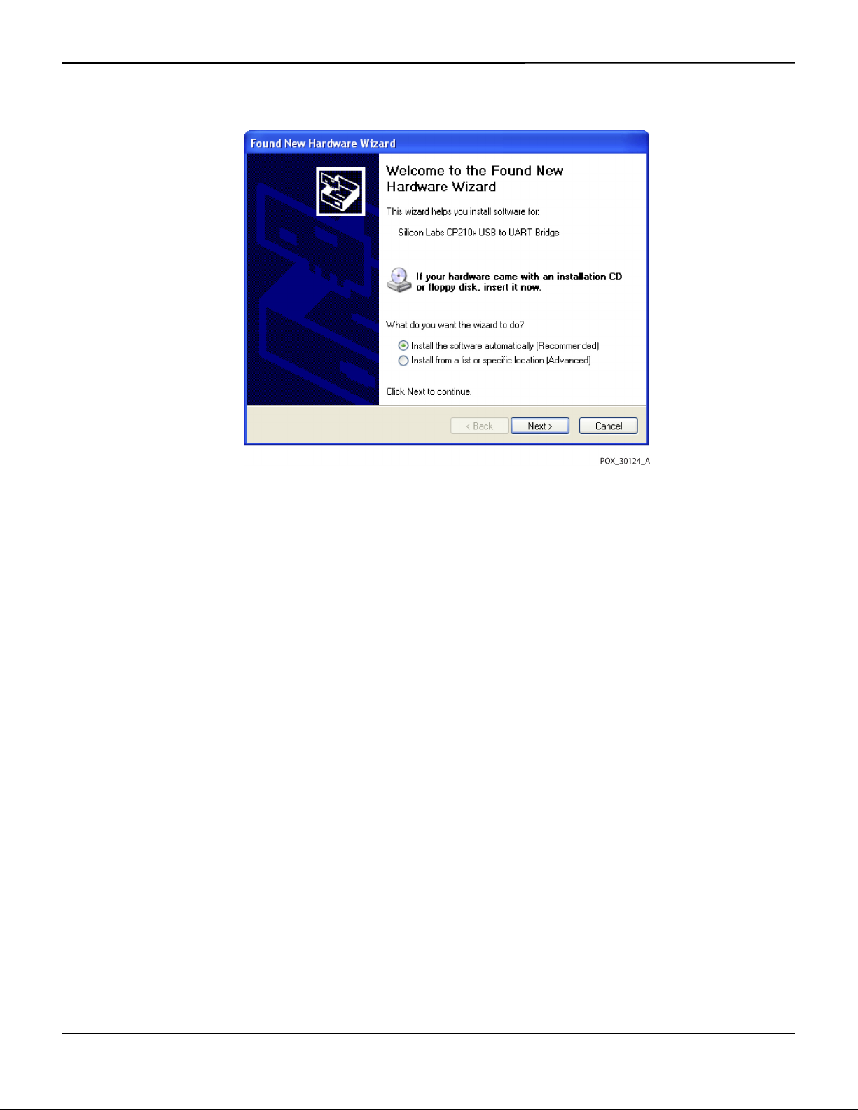
Data Management
Figure5-8.Sample New Hardware Wizard Screen
11. At the prompt from the installer, click on the NEXT button to copy the driver to the PC.
12. When the installer provides the end-user license agreement, read it carefully, then click the button for
accepting the terms of the license.
13. Click NEXT to formally accept the agreement.
14. Review the Destination Folder mapping. To change the destination, click BROWSE and select the
desired mapping.
15. Click NEXT to formally accept the Destination Folder mapping.
16. Click INSTALL in the resulting driver installer window. Do not click the CANCEL button
Note:
If a Windows™* Security window pops up, select the option to install the driver anyway.
17. Click the OK button to complete the installation in the resulting Success window.
18. Reboot the PC for changes to take effect.
19. From the START menu, click the Settings menu option and select the Control Panel option.
20. Select the System option to open the System Properties window.
21. Click the Hardware tab, then the DEVICE MANAGER button.
5-12 Operator’s Manual

Figure5-9.Sample DEVICE MANAGER Button Under Hardware Tab
External Data Communication
22. Select the Ports option from the resulting list.
Operator’s Manual 5-13

Data Management
Figure5-10.Sample Hardware List in Device Manager Window
23. Double click the Silicon Labs CP210x USB to UART Bridge option.
Note:
The listed COM port should match the HyperTerminal™* COM port designation. Reference To launch
HyperTerminal™*:, p. 5-8.
5-14 Operator’s Manual

Figure5-11.Sample Initial USB to UART Bridge Properties Window
External Data Communication
24. Click the Port Settings tab.
25. Set the bits per second to one of four possible baud rates: 19200, 38400, 57600, or 115200. The factory
default is 19200 bps.
Operator’s Manual 5-15

Data Management
Figure5-12.Sample Baud Rate List Under Port Settings Tab
26. Click the OK button to complete the process.
27. Reference To download trend data, p. 5-6, and proceed to step 8, utilizing HyperTerminal™* to connect
to the monitoring system.
5.4.3 Firmware Upgrades
Contact a qualified service technician to perform any firmware upgrade to the monitoring system,
as described in the Service Manual.
5-16 Operator’s Manual

6 Performance Considerations
6.1 Overview
This chapter contains information about optimizing the performance of the Nellcor™ bedside
patient monitoring system.
SpO
2
Verify the performance of the monitoring system by following the procedures outlined in the
Service Manual. Have a qualified service technician perform these procedures prior to initial
installation in a clinical setting.
6.2 Oximetry Considerations
WARNING:
Pulse oximetry readings and pulse signals can be affected by certain ambient environmental
conditions, pulse oximetry sensor application errors, and certain patient conditions.
6.2.1 Pulse Rates
The monitoring system only reports pulse rates between 20 and 250 bpm. Detected pulse rates
above 250 bpm appear as 250. Detected pulse rates below 20 appear as a zero (0).
6.2.2 Saturation
The monitoring system reports saturation levels between 1% and 100%.
6.3 Performance Considerations
6.3.1 Overview
This section contains information for optimizing the performance of the monitoring system.
Verify the performance of the monitoring system by following the procedures outlined in the
SRC-MAX Pulse Oximetry Functional Tester Technical Manual. Have a qualified service technician
6-1

Performance Considerations
perform these procedures prior to initial installation in a clinical setting and every 24 months as
part of preventive maintenance. Reference Service, p. 7-4.
6.3.2 Patient Conditions
Application issues and certain patient conditions can affect the measurements of the monitoring
system and cause the loss of the pulse signal.
• Anemia — Anemia causes decreased arterial oxygen content. Although SpO
normal, an anemic patient may be hypoxic. Correcting anemia can improve arterial oxygen content.
The monitoring system may fail to provide an SpO
• Dysfunctional hemoglobins — Dysfunctional hemoglobins such as carboxyhemoglobin,
methemoglobin, and sulphemoglobin are unable to carry oxygen. SpO
however, a patient may be hypoxic because less hemoglobin is available to carry oxygen. Further
assessment beyond pulse oximetry is recommended.
• Additional possible patient conditions may also influence measurements.
– Poor peripheral perfusion
readings may appear
2
reading if hemoglobin levels fall below 5 gm/dl.
2
readings may appear normal;
2
– Excessive patient activity
– Venous pulsations
– Dark skin pigment
– Intravascular dyes, such as indocyanine green or methylene blue
– Externally applied coloring agents (nail polish, dye, pigmented cream)
– Defibrillation
6.3.3 Sensor Performance Considerations
WARNING:
Pulse oximetry readings and pulse signal can be affected by certain ambient conditions, sensor
application errors, and certain patient conditions.
WARNING:
Tissue damage can be caused by incorrect application or inappropriate duration of use of a pulse
oximetry sensor. Inspect the sensor site as directed in the Instructions for Use.
6-2 Operator’s Manual

WARNING:
Use only Covidien-approved pulse oximetry sensors and pulse oximetry cables when connecting
to the sensor connector. Connecting any other cable or sensor influences the accuracy of sensor
data, since this may lead to adverse results.
WARNING:
Failure to cover the pulse oximetry sensor site with opaque material in high ambient light
conditions may result in inaccurate measurements.
Inaccurate Sensor Measurement Conditions
A variety of conditions can cause inaccurate Nellcor™ pulse oximetry sensor measurements.
• Incorrect application of the pulse oximetry sensor
• Placement of the pulse oximetry sensor on an extremity with a blood pressure cuff, arterial catheter, or
intravascular line
• Ambient light
Performance Considerations
• Failure to cover the pulse oximetry sensor site with opaque material in high ambient light conditions
• Excessive patient activity
• Dark skin pigment
• Intravascular dyes or externally applied coloring, such as nail polish or pigmented cream
Signal Loss
Loss-of-pulse signal can occur for several reasons.
• Pulse oximetry sensor applied too tightly
• Inflation of a blood pressure cuff on the same extremity as the attached pulse oximetry sensor
• Arterial occlusion proximal to the pulse oximetry sensor
• Poor peripheral perfusion
Recommended Usage
Select an appropriate Nellcor™ pulse oximetry sensor, apply it as directed, and observe all
warnings and cautions presented in the Instructions for Use accompanying the sensor. Clean and
remove any substances such as nail polish from the application site. Periodically check to ensure
that the sensor remains properly positioned on the patient.
High ambient light sources such as surgical lights (especially those with a xenon light source),
bilirubin lamps, fluorescent lights, infrared heating lamps, and direct sunlight can interfere with
Operator’s Manual 6-3

Performance Considerations
the performance of a Nellcor™ pulse oximetry sensor. To prevent interference from ambient light,
ensure that the sensor is properly applied, and cover the sensor site with opaque material.
If patient activity presents a problem, try one or more of the following remedies to correct the problem.
• Verify the Nellcor™ pulse oximetry sensor is properly and securely applied.
• Move the sensor to a less active site.
• Use an adhesive sensor that improves patient skin contact.
• Use a new sensor with fresh adhesive backing.
• Keep the patient still, if possible.
If poor perfusion affects performance, consider using the Nellcor™ forehead SpO2 sensor (MAXFAST), which provides superior detection in the presence of vasoconstriction. Nellcor™ forehead
sensors work particularly well on supine patients and mechanically ventilated patients.
SpO
2
During low perfusion conditions, Nellcor™ forehead SpO2 sensors reflect changes to SpO2 values
up to 60 seconds earlier than digit sensors.
6.3.4 Reducing EMI (Electromagnetic Interference)
WARNING:
Keep patients under close surveillance when monitoring. It is possible, although unlikely, that
radiated electromagnetic signals from sources external to the patient and the monitoring system
can cause inaccurate measurement readings.
WARNING:
Any radio frequency transmitting equipment or other nearby sources of electrical noise may result
in disruption of the monitoring system.
WARNING:
Large equipment using a switching relay for its power on/off may affect monitoring system
operation. Do not operate the monitoring system in such environments.
WARNING:
The monitoring system is designed for use in environments in which the signal can be obscured by
electromagnetic interference. During such interference, measurements may seem inappropriate
or the monitoring system may not seem to operate correctly.
Caution:
This device has been tested and found to comply with the limits for medical devices related to IEC
60601-1-2:2007 and IEC 60601-1-2:2014. These limits are designed to provide reasonable
protection against harmful interference in a typical medical installation.
6-4 Operator’s Manual

Obtaining Technical Assistance
Because of the proliferation of radio frequency transmitting equipment and other sources of
electrical noise in health care environments (for example, electrosurgical units, cellular phones,
mobile two-way radios, electrical appliances, and high-definition television), it is possible that
high levels of such interference due to close proximity or strength of a source may result in
disruption of monitoring system performance.
Disruption may be evidenced by erratic readings, cessation of operation, or other incorrect
functioning. If this occurs, survey the site of use to determine the source of this disruption, then
take the appropriate actions to eliminate the source.
• Turn equipment in the vicinity off and on to isolate the offending equipment.
• Reorient or relocate the interfering equipment.
• Increase the separation between the interfering equipment and the monitoring system.
• Connect the equipment into an outlet on a circuit different from that to which the other device(s) are
connected.
The monitoring system generates, uses, and can radiate radio frequency energy and, if not
installed and used in accordance with these instructions, may cause harmful interference with
other susceptible devices in the vicinity. Contact Technical Services for assistance.
6.4 Obtaining Technical Assistance
For technical information and assistance, contact Technical Services or a qualified service
technician. Reference Obtaining Technical Assistance, p. 1-5.
Operator’s Manual 6-5

Performance Considerations
Page Left Intentionally Blank
6-6 Operator’s Manual

7 Preventive Maintenance
7.1 Overview
This chapter describes the steps required to maintain, service, and properly clean the Nellcor™
bedside SpO
7.2 Cleaning
patient monitoring system.
2
WARNING:
Do not spray, pour, or spill any liquid on the monitoring system, its accessories, connectors,
switches, or openings in the chassis.
WARNING:
Remove batteries from the monitoring system before cleaning.
For surface cleaning and disinfection of the monitoring system, follow institutional procedures
or the recommended actions below.
• Surface cleaning — Surface clean the monitoring system by using a soft cloth dampened with a
commercial, nonabrasive cleaner. Lightly wipe the top, bottom, and front surfaces of the monitoring
system lightly.
• Disinfection — Use a soft cloth saturated with a solution of 10% chlorine bleach in tap water, lightly
wiping the surface of the monitoring system.
For sensors, follow cleaning instructions in the instructions for use shipped with those
components. Before attempting to clean a Nellcor™ pulse oximetry sensor, read the Instructions
for Use enclosed with the sensor. Each sensor model has cleaning instructions specific to that
sensor. Follow the pulse oximetry sensor cleaning and disinfecting procedures in the particular
sensor's Instructions for Use.
Avoid spilling liquid on the monitoring system, especially in connector areas, but if a spill occurs,
clean and thoroughly dry the monitoring system before reuse. If in doubt about monitoring
system safety, refer the monitoring system to a qualified service technician for examination.
7-1

Preventive Maintenance
Recycling and Disposal
7.3
When the monitoring system, battery, or accessories reach the end of useful life, recycle or
dispose of the equipment according to appropriate local and regional regulations.
7.4 Battery Maintenance
WARNING:
Explosion hazard — Do not use the battery with other manufacturer's batteries, different types or
models of batteries such as dry batteries, nickel-metal hydride batteries, or Lithium-ion batteries
together.
WARNING:
Explosion hazard — Do not connect the battery reversed in positive (+) and negative (-) terminals.
Do not charge the battery with polarities reversed.
Caution:
Covidien strongly recommends recharging the battery when it has not been recharged for six (6)
or more months.
Caution:
Follow local government ordinances and recycling instructions regarding disposal or recycling of
device components, including batteries.
Caution:
Do not short-circuit the battery, as it may generate heat. To avoid short-circuiting, do not let the
battery come in contact with metal objects at any time, especially during transport.
Caution:
Do not solder the battery directly. Heat applied during soldering may damage the safety vent in
the battery's positive cover.
Caution:
Do not deform the battery by applying pressure. Do not throw, hit, drop, fold or impact the
battery.
Caution:
Do not use any chargers not specified by Covidien.
7-2 Operator’s Manual

Caution:
Do not mistreat the battery, or use the battery in applications not recommended by Covidien.
Caution:
Keep the battery out of reach of children to avoid any accidents.
Caution:
If there are any problems with the battery, immediately put the monitoring system in a safe place
and contact a qualified service technician.
Note:
The service menu displays the number of deep discharge cycles seen by the battery. The monitoring
system records a deep discharge cycle when the battery reaches the voltage after a “critically low battery”
alarm issues. Reference the Service Manual.
Note:
Remove the battery if anticipating long periods of time between use or if storing the monitoring system.
Periodic Safety Checks
Note:
Storing the monitoring system for a long period without charging the battery may degrade battery
capacity. A full charge of a depleted battery takes over four (4) or eight (8) hours, depending on the battery.
Regularly check the battery to ensure optimal performance.
• Charge the lithium-ion battery if the monitoring system has not been used for six (6) months. To
charge the battery, connect the monitoring system to AC power.
• Have a qualified service technician replace the monitoring system's lithium-ion battery every two (2)
years. Reference the Service Manual for battery replacement and general service instructions.
7.5 Periodic Safety Checks
Covidien recommends a qualified service technician perform the following checks every 24
months.
• Inspect the equipment for mechanical and functional damage or deterioration.
• Inspect the safety relevant labels for legibility. Contact Covidien or a local Covidien representative, if
labels are damaged or illegible.
• Ensure all user interface keys, cables, and accessories function normally.
Operator’s Manual 7-3

Preventive Maintenance
Service
7.6
WARNING:
Only a qualified service technician should remove the cover or access any internal components.
Caution:
Dispose of monitoring system in accordance with local requirements and regulations.
The monitoring system requires no routine service other than cleaning, battery maintenance, and
service activity mandated by the institution. For more information, reference the Service Manual.
• The monitoring system requires no calibration.
• Have a qualified service technician replace the battery at least every two (2) years.
• If service is necessary, contact Technical Services or a qualified service technician. Reference Obtaining
Technical Assistance, p. 1-5.
7-4 Operator’s Manual

8 Troubleshooting
8.1 Overview
This chapter describes how to troubleshoot common problems while using the Nellcor™
bedside SpO
8.2 General
patient monitoring system.
2
WARNING:
Check the patient's vital signs by alternate means should there be any doubt about the accuracy
of any measurement. Request a qualified service technician confirm the monitoring system is
functioning correctly.
WARNING:
Only a qualified service technician should remove the cover or access any internal components.
If the monitoring system detects an error, it displays an appropriate error code. The Service
Manual lists all error codes. If an error occurs, check and reseat all power connections and ensure
the battery is fully charged. If the error persists, write down the error code and contact Technical
Services or a qualified service technician.
8-1

Troubleshooting
Error Conditions
8.3
Battery Charging Indicator not lit Check power cord
Table8-1.Common Problems and Resolutions
Problem Resolution
Check battery
Check AC power inlet
Check power/ mains outlet
Sensor Message
SpO
Pulse search
2
Signal Artifact Detected
Sensor Off
SpO
2
Cable/Sensor Disconnect
SpO
2
Loss of Pulse
SpO
2
No response to Power On/Off
button press
No response to button press Verify whether the Return button has not been pressed during normal screen.
Reference Performance Considerations, p. 6-1.
Check patient status; keep patient still, check for perfusion
Check all connections
Reposition sensor
Check or change adhesive wrap
Choose alternate site
Warm site
Cover sensor
Use forehead, nasal, or ear sensor (adult patient only)
Use Nellcor™ adhesive sensor
Secure cable
Secure with headband (MAX-FAST)
Remove nail polish
Loosen sensor (too tight)
Isolate external interference (electrosurgical device, cell phone)
Replace the cable and/or sensor
Clean site (MAX-R)
Press the Power On/Off button for more than one (1) second.
Ensure the power cord is properly connected to the outlet.
Ensure AC indicator blinks.
Ensure it does not share the same AC power source with other equipment.
If the error continues, contact Technical Services or a qualified service technician.
If the error continues, contact Technical Services or a qualified service technician.
Frozen at POST after power on Power cycle by pressing the Power On/Off button.
If the error continues, contact Technical Services or a qualified service technician.
System is frozen If the system freezes, it generates beep tone. Press the power button over 15 seconds for
force quit the system.
If the error continues, contact Technical Services or a qualified service technician.
Blank screen Ensure buttons light. If not, press the Power On/Off button to turn on.
Check if AC indicator lights or blinks.
Use the same AC power source with other equipment to check for power.
If the error continues, contact Technical Services or a qualified service technician.
Screen does not function
properly and the power-on beep
tones do not sound
8-2 Operator’s Manual
Do not use the monitoring system; contact a qualified service technician or Covidien
Technical Services.

Table8-1.Common Problems and Resolutions (Continued)
Problem Resolution
No sound generation Verify setting point of volume is not 0 or 1.
Verify alarm setup is not set to alarm silenced.
If the error continues, contact Technical Services or a qualified service technician.
Error Conditions
Abnormally shut down last time
message
Date and Time incorrect Set the time in the Options Menu.
System consumes battery power
even with AC power connection
Low Battery / Critically LowBattery condition
Check any temporary settings such as alarm limits, response mode, and patient mode,
since resets invoke factory or institutional default settings.
Press the Power On/Off button to reset system power.
If the error continues, contact Technical Services or a qualified service technician.
Check if date setting format follows locale.
If the system displays wrong date and time even after power reset, it means internal
battery for power backup is dead.
If the error continues, contact Technical Services or a qualified service technician.
Ensure proper connection between power cord and wall socket.
Check if AC indicator lights or blinks.
Use the same AC power source with other equipment to check for power.
Replace the power cord.
If the error continues, contact Technical Services or a qualified service technician.
Connect the system to AC power until the internal battery is fully charged.
Ensure the system power cord is connected to the wall socket properly.
Check if AC indicator lights or blinks.
Use the same AC power source with other equipment to check for power.
Check the date of manufacture (DOM) of battery.
If the error continues, contact Technical Services or a qualified service technician.
Questionable readouts of patient
physiological measurements,
wrongly tagged or missing
patient data
Data port does not function
properly
Experiencing EMI interference Reference Reducing EMI (Electromagnetic Interference), p. 6-4.
Technical System Error Do not use the monitoring system; contact a qualified service technician or Covidien
Reference Performance Considerations, p. 6-1.
Check patient status.
Replace sensor or cable, if necessary.
Check all connections and reposition, if necessary.
Remove sources of electromagnetic interference.
Remove excessive ambient light.
Ensure USB cable firmly connected.
Disconnect USB cable, reset system power, then reconnect.
Ensure baud rate settings for both monitoring system and PC are the same.
Check hardware tab in PC 'System Registration Information'; verify normal status.
Check COM port.
Re-install the bridge driver provided by Covidien.
Technical Services.
Operator’s Manual 8-3

Troubleshooting
Reference Managing Alarms and Alarm Limits, p. 4-14, for any issues related to alarm conditions.
8.4 Return
Contact Covidien or a local Covidien representative for shipping instructions, including a
Returned Goods Authorization (RGA) number. Reference Obtaining Technical Assistance, p. 1-5.
Unless otherwise instructed by Covidien, it is not necessary to return the sensor or other accessory
items with the monitoring system. Pack the monitoring system in its original shipping carton. If
the original carton is not available, use a suitable carton with the appropriate packing material to
protect it during shipping. Return the monitoring system by any shipping method that provides
proof of delivery.
8-4 Operator’s Manual

9 Accessories
9.1 Overview
This chapter contains information for selecting the appropriate pulse oximetry sensor for use
with the Nellcor™ bedside SpO
9.2 Nellcor™ Pulse Oximetry Sensors
patient monitoring system.
2
WARNING:
Before use, carefully read the pulse oximetry sensor Instructions for Use, including all warnings,
cautions, and instructions.
WARNING:
Use only Nellcor™-approved pulse oximetry sensors and pulse oximetry cables when connecting
to the sensor connector. Connecting any other cable or sensor influences the accuracy of the
sensor data, which may lead to adverse results.
WARNING:
Do not use a damaged pulse oximetry sensor or pulse oximetry cable. Do not use a sensor with
exposed optical components.
WARNING:
Tissue damage can be caused by incorrect application or duration of use of a pulse oximetry
sensor. Inspect the sensor site periodically as directed in the sensor Instructions for Use.
WARNING:
Pulse oximetry readings and pulse signal can be affected by certain ambient environmental
conditions, sensor application errors, and certain patient conditions.
WARNING:
Do not immerse or wet the pulse oximetry sensor.
9-1

Accessories
Caution:
Nellcor™ adhesive pulse oximetry sensors are intended for single-patient use only. Do not reuse
pulse oximetry sensors.
When selecting a Nellcor™ pulse oximetry sensor, consider the following items: patient’s weight
and activity level, the adequacy of perfusion, and the available sensor sites, the need for sterility,
and the anticipated duration of monitoring. Use the following table for selection or contact
Covidien or a local Covidien representative. Reference Sensor Performance Considerations, p. 6-2.
Use the Nellcor™ pulse oximetry interface cable to connect the pulse oximetry sensor to the
monitoring system.
Table9-1.Nellcor™ Pulse Oximetry Sensor Models and Patient Sizes
Nellcor™ pulse oximetry sensor SKU Patient
size
Nellcor™ preemie SpO2 sensor, non-adhesive (single-patient use) SC-PR <1.5 kg
Nellcor™ neonatal SpO
Nellcor™ adult SpO
Nellcor™ adult-neonatal SpO
Nellcor™ pediatric-infant SpO
Nellcor™ pediatric SpO
Nellcor™ neonatal-adult SpO
Nellcor™ adult SpO
Nellcor™ neonatal-adult SpO
Nellcor™ infant SpO
Nellcor™ pediatric SpO
Nellcor™ adult SpO
Nellcor™ adult XL SpO
Nellcor™ adult SpO
Nellcor™ forehead SpO
Nellcor™ adult SpO
sensor, non-adhesive (single-patient use) SC-NEO 1.5 to 5 kg
2
sensor, non-adhesive (single-patient use) SC-A >40 kg
2
sensor, two piece (sterile, single-use only) P 10 to 50 kg
2
sensor, two piece (sterile, single-use only) A > 30 kg
2
sensor (sterile, single-use only) MAX-I 3 to 20 kg
2
sensor (sterile, single-use only) MAX-P 10 to 50 kg
2
sensor (sterile, single-use only) MAX-A >30 kg
2
sensor (sterile, single-use only) MAX-AL >30 kg
2
nasal sensor (sterile, single-use only) MAX-R >50 kg
2
sensor MAX-FAST >10 kg
2
sensor, reusable (nonsterile) DS-100A >40 kg
2
sensor with wraps (reusable with adhesive) OXI-A/N <3 or >40 kg
2
sensor with wraps (reusable with adhesive) OXI-P/I 3 to 40 kg
2
sensor, two piece (sterile, single-use only) N <3 or >40 kg
2
sensor (sterile, single-use only) MAX-N <3 or >40 kg
2
Nellcor™ SpO
Nellcor™ SpO
Nellcor™ pediatric SpO
9-2 Operator’s Manual
sensor, multisite reusable (nonsterile) D-YS >1 kg
2
ear clip, reusable (nonsterile) D-YSE >30 kg
2
clip, reusable (nonsterile) D-YSPD 3 to 40 kg
2

Optional Equipment
Table9-1.Nellcor™ Pulse Oximetry Sensor Models and Patient Sizes (Continued)
Nellcor™ pulse oximetry sensor SKU Patient
size
Nellcor™ flexible SpO2 sensor (reusable, large) FLEXMAX >20 kg
Nellcor™ flexible SpO
Nellcor™ flexible SpO
Nellcor™ flexible SpO
sensor (reusable, small) FLEXMAX-P >20 kg
2
sensor (reusable, large, home care) FLEXMAX-HC >20 kg
2
sensor (reusable, small, home care) FLEXMAX-P-HC >20 kg
2
Note:
Physiological conditions, medical procedures, or external agents that may interfere with the monitoring
system’s ability to detect and display measurements include dysfunctional hemoglobin, arterial dyes, low
perfusion, dark pigment, and externally applied coloring agents such as nail polish, dye, or pigmented
cream.
9.3 Optional Equipment
Contact Covidien or a local Covidien representative for more information about optional
equipment for use with the monitoring system.
Adapter plate—Fits standard,
commercially available GCX brackets and
securely mounts the monitoring system to
a wall bracket or a roll stand.
Operator’s Manual 9-3

Accessories
GCX wall mount arm and channel—
Attaches to the adapter plate, which
attaches to the arm.
GCX roll stand—Attaches to the adapter
plate.
Covidien Technical Services: Patient Monitoring
15 Hampshire Street, Mansfield, MA 02048 USA
1.800.635.5267, 1.925.463.4635
or contact a local Covidien representative
www.covidien.com
9.4
Biocompatibility Testing
Biocompatibility testing has been conducted on Nellcor™ pulse oximetry sensors in compliance
with ISO 10993-1, Biological Evaluation of Medical Devices, Part 1: Evaluation and Testing. The
pulse oximetry sensors have passed the recommended biocompatibility testing and are therefore
in compliance with ISO 10993-1.
9-4 Operator’s Manual

10 Theory of Operations
10.1 Overview
This chapter explains the theory behind operations of the Nellcor™ bedside SpO2 patient
monitoring system.
10.2 Theoretical Principles
The monitoring system uses pulse oximetry to measure functional oxygen saturation in the
blood. Pulse oximetry works by applying a Nellcor™ pulse oximetry sensor to a pulsating
arteriolar vascular bed, such as a finger or toe. The sensor contains a dual light source and a
photodetector.
Bone, tissue, pigmentation, and venous vessels normally absorb a constant amount of light over
time. The arteriolar bed normally pulsates and absorbs variable amounts of light during the
pulsations. The ratio of light absorbed is translated into a measurement of functional oxygen
saturation (SpO
).
2
Ambient conditions, sensor application, and patient conditions can influence the ability of the
pulse oximeter to accurately measure SpO
. Reference Performance Considerations, p. 6-1.
2
Pulse oximetry is based on two principles: oxyhemoglobin and deoxyhemoglobin differ in their
absorption of red and infrared light (measured using spectrophotometry), and the volume of
arterial blood in tissue (and hence, light absorption by that blood) changes during the pulse
(registered using plethysmography). A monitoring system determines SpO
by passing red and
2
infrared light into an arteriolar bed and measuring changes in light absorption during the
pulsatile cycle. Red and infrared low-voltage light-emitting diodes (LED) in the sensor serve as
light sources; a photo diode serves as the photo detector.
Since oxyhemoglobin and deoxyhemoglobin differ in light absorption, the amount of red and
infrared light absorbed by blood is related to hemoglobin oxygen saturation.
The monitoring system uses the pulsatile nature of arterial flow to identify the oxygen saturation
of arterial hemoglobin. During systole, a new pulse of arterial blood enters the vascular bed, and
blood volume and light absorption increase. During diastole, blood volume and light
absorption reach their lowest point. The monitoring system bases its SpO
measurements on
2
the difference between maximum and minimum absorption (measurements at systole and
10-1

Theory of Operations
diastole). By doing so, it focuses on light absorption by pulsatile arterial blood, eliminating the
effects of nonpulsatile absorbers such as tissue, bone, and venous blood.
10.3 Automatic Calibration
Because light absorption by hemoglobin is wavelength dependent and because the mean
wavelength of LEDs varies, a monitoring system must know the mean wavelength of the pulse
oximetry sensor's red LED to accurately measure SpO
During monitoring, the monitoring system’s software selects coefficients that are appropriate for
the wavelength of that individual sensor's red LED; these coefficients are then used to determine
.
SpO
2
Additionally, to compensate for differences in tissue thickness, the light intensity of the sensor's
LEDs is adjusted automatically.
Note:
During certain automatic calibration functions, the monitoring system may briefly display a flat line on the
plethysmographic waveform. This is a normal operation and does not require any user intervention.
.
2
10.4 Functional Testers and Patient Simulators
Some models of commercially available bench top functional testers and patient simulators can
be used to verify the proper functionality of Nellcor™ monitoring systems, sensors, and cables.
Reference the individual testing device's operator's manual for the procedures specific to the
model of tester used. While such devices may be useful for verifying that the sensor, cabling, and
monitoring system are functional, they are incapable of providing the data required to properly
evaluate the accuracy of a system's SpO
measurements.
2
Fully evaluating the accuracy of the SpO2 measurements requires, at a minimum,
accommodating the wavelength characteristics of the sensor and reproducing the complex
optical interaction of the sensor and the patient’s tissue. These capabilities are beyond the scope
of known bench top testers. SpO
measurement accuracy can only be evaluated in vivo by
2
comparing monitoring system readings with values traceable to SaO2 measurements obtained
from simultaneously sampled arterial blood using a laboratory CO-oximeter.
Many functional testers and patient simulators have been designed to interface with the
monitoring system's expected calibration curves and may be suitable for use with monitoring
systems and/or sensors. Not all such devices, however, are adapted for use with the OxiMax™
digital calibration system. While this will not affect use of the simulator for verifying system
functionality, displayed SpO
measurement values may differ from the setting of the test device.
2
For a properly functioning monitoring system, this difference will be reproducible over time and
from monitoring system to monitoring system within the performance specifications of the test
device.
10-2 Operator’s Manual

Unique Technologies
Unique Technologies
10.5
10.5.1 Functional versus Fractional Saturation
This monitoring system measures functional saturation where oxygenated hemoglobin is
expressed as a percentage of the hemoglobin that can transport oxygen. It does not detect
significant amounts of dysfunctional hemoglobin, such as carboxyhemoglobin or
methemoglobin. In contrast, hemoximeters such as the IL482 report fractional saturation where
oxygenated hemoglobin is expressed as a percentage of all measured hemoglobin, including
measured dysfunctional hemoglobins. To compare functional saturation measurements to those
from a monitoring system that measures fractional saturation, fractional measurements must be
converted using the listed equation.
---------------------------------
100=
100 +–
functional saturation %carboxyhemoglobin
fractional saturation %methemoglobin
10.5.2 Measured versus Calculated Saturation
When calculating saturation from a blood gas partial pressure of oxygen (PO2), the calculated
value may differ from the SpO2 measurement of a monitoring system. This usually occurs when
saturation calculations exclude corrections for the effects of variables such as pH, temperature,
the partial pressure of carbon dioxide (PCO
), and 2,3-DPG, that shift the relationship between
2
PO2 and SpO2.
Operator’s Manual 10-3

Theory of Operations
Figure10-1.Oxyhemoglobin Dissociation Curve
1 % Saturation Axis 3 Increased pH; Decreased temperature, PCO2, and 2,3-DPG
2PO
(mmHg) Axis 4 Decreased pH; Increased temperature, PCO2, and 2,3-DPG
2
10.5.3
Data Update Period, Data Averaging, and Signal Processing
The advanced signal processing of the OxiMax™ algorithm automatically extends the amount of data
required for measuring SpO
and pulse rate depending on the measurement conditions. The OxiMax™
2
algorithm automatically extends the dynamic averaging time required beyond seven (7) seconds
during degraded or difficult measurement conditions caused by low perfusion, signal artifact, ambient
light, electrocautery, other interference, or a combination of these factors, which results in an increase
in the dynamic averaging. If the resulting dynamic averaging time exceeds 20 seconds for SpO
algorithm sets the pulse search bit while continuing to update SpO2 and pulse rate values every
second.
As such measurement conditions extend, the amount of data required may continue to increase.
If the dynamic averaging time reaches 40 seconds, and/or 50 seconds for pulse rate, a low priority
alarm state results: the algorithm sets the Pulse Timeout bit and the monitoring system reports a
zero saturation indicating a loss-of-pulse condition, which should result in an audible alarm.
, the
2
10-4 Operator’s Manual

SatSeconds™ Alarm Management Feature
SatSeconds™ Alarm Management Feature
10.6
The monitoring system monitors the percentage of hemoglobin binding sites saturated with
oxygen in the blood. With traditional alarm management, upper and lower alarm limits are set to
alarm at specific SpO
levels. When the SpO2 level fluctuates near an alarm limit, the alarm sounds
2
each time it violates the alarm threshold. SatSeconds™ monitors both degree and duration of
desaturation as an index of desaturation severity. Thus, the SatSeconds™ feature helps distinguish
clinically significant events from minor and brief desaturations that may result in nuisance alarms.
Consider a series of events leading to a violation of the SatSeconds™ alarm limit. An adult patient
experiences several minor desaturations, then a clinically significant desaturation.
Figure10-2.Series of SpO2 Events
a First SpO2 Event
10.6.1
First SpO2 Event
b Second SpO
c Third SpO
2
Event
2
Event
Consider the first event. Suppose the SatSeconds™ alarm limit is set to 25. The patient’s SpO2
drops to 79% and the duration of the event is two (2) seconds before saturation again exceeds
the lower alarm threshold of 85%.
6% drop below the lower alarm limit threshold
x 2 second duration below the lower threshold
12 SatSeconds™; no alarm
Because the SatSeconds™ alarm limit is set to 25 and the actual number of SatSeconds™ equals
12, there is no audible alarm.
Operator’s Manual 10-5

Theory of Operations
Figure10-3.First SpO2 Event: No SatSeconds™ Alarm
10.6.2 Second SpO
Event
2
Consider the second event. Suppose the SatSeconds™ alarm limit is still set to 25. The patient’s
drops to 84% and the duration of the event is 15 seconds before saturation again exceeds
SpO
2
the lower alarm threshold of 85%.
1% drop below the lower alarm limit threshold
x15 second duration below the lower threshold
15 SatSeconds™; no alarm
Because the SatSeconds™ alarm limit is set to 25 and the actual number of SatSeconds™ equals
15, there is no audible alarm.
10-6 Operator’s Manual

SatSeconds™ Alarm Management Feature
Figure10-4.Second SpO2 Event: No SatSeconds™ Alarm
10.6.3
Third SpO2 Event
Consider the third event. Suppose the SatSeconds™ alarm limit is still set to 25. During this event,
the patient’s SpO
drops to 75%, which is 10% below the lower alarm threshold of 85%. Since the
2
patient’s saturation does not return to a value over the lower alarm threshold within 2.5 seconds,
an alarm sounds.
10% drop below the lower alarm limit threshold
x2.5 second duration below the lower threshold
25 SatSeconds™; results in an alarm
At this level of saturation, the event cannot exceed 2.5 seconds without invoking a SatSeconds™
alarm.
Operator’s Manual 10-7

Theory of Operations
Figure10-5.Third SpO2 Event: Triggers SatSeconds™ Alarm
10.6.4
The SatSeconds™ Safety Net
The SatSeconds™ “Safety Net” is for patients with saturation levels frequently below the limit, but
not staying below the limit long enough for the SatSeconds™ time setting to be reached. When
three or more limit violations occur within 60 seconds, an alarm sounds even if the SatSeconds™
time setting has not been reached.
10-8 Operator’s Manual

11 Product Specifications
11.1 Overview
This chapter contains physical and operational specifications of the Nellcor™ bedside SpO2
patient monitoring system. Ensure all product requirements are met prior to installation of the
monitoring system.
11.2 Physical Characteristics
Enclosure
Weight 1.6 kg (3.5 lbs.) including battery
Dimensions 255 × 82 × 165 mm (10.04 x 3.23 x 6.50 in)
Display
Screen size 109.22 mm (4.3 in), measured diagonally
Screen type TFT LCD, white LED backlight, viewing cone of 30° and optimal
viewing distance of 1 meter
Resolution 480 × 272 pixel
Controls
Dial Jog dial control
Buttons Power On/Off, Silence Alarm, Return
Alarms
Categories Patient status and system status
Priorities Low, medium and high
Notification Audible and visual
Setting Default and individual
Alarm volume level 45 to 80 dB
11-1

Product Specifications
Electrical
11.3
Battery power requirement AC 100-240VAC, 50/60Hz, 45 VA
Voltage and capacity of Li-Ion, 5 hour
Voltage and capacity of Li-Ion, 10hour
Compliance 91/157/EEC
Fast-acting fuse 2A 32VAC,/DC
Fast-acting fuse 500 mA 32VAC/50DC
1. New batteries typically provide the stated duration when operating in Normal Response Mode, with pulse
beep, the SatSeconds™ feature enabled, with no external communication, no audible alarms, and at 25 °C ±
5°C.
11.4 Environmental Conditions
Note:
The system may not meet its performance specifications if stored or used outside the specified
temperature and humidity range.
1
1
10.8 V/ 2200 mAh
10.8 V/4400 mAh
Table11-1.Transport, Storage, and Operating Condition Ranges
Transport and storage Operating conditions
Temperature -20 °C to 60 °C,
(-4 °F to 140 °F)
Altitude -304 to 6,096 m,
(-1,000 to 20,000 ft.)
Pressure 50 kPa to 106 kPa,
(14.7 in. Hg to 31.3 in. Hg)
Relative
humidity
5 °C to 40 °C
(41 °F to 104 °F)
-170 to 4,877 m,
(-557 to 16,000 ft.)
58 kPa to 103 kPa,
(17.1 in. Hg to 30.4 in. Hg)
15% to 93% non-condensing
11-2 Operator’s Manual

Tone Definition
11.5
Volume level Adjustable (level 1-8)
Pitch (± 20Hz) 976 Hz
Pulse width (± 20msec) 150 msec (IEC60601-1-8)
Number of pulses in burst 10, interburst interval of 4 sec (IEC60601-1-8)
Repetitions Continually
Volume level Adjustable (level 1-8)
Pitch (± 20Hz) 697 Hz
Tone Definition
Table11-2.Tone Definitions
Tone category Description
High priority alarm tone
Medium priority alarm tone
Pulse width (± 20msec) 150 msec (IEC60601-1-8)
Number of pulses in burst 3, interburst interval of 8 sec (IEC60601-1-8)
Repetitions Continually
Low priority alarm tone
Volume level Adjustable (level 1-8)
Pitch (± 20Hz) 488 Hz
Pulse width (± 20msec) 250 msec (IEC60601-1-8)
Number of pulses 1, interburst interval of 16 sec (IEC60601-1-8)
Repetitions Continually
Alarm disabled reminder tone
Volume level Not changeable
Pitch (± 20Hz) 800 Hz
Pulse width (± 20msec) 200 msec
Number of pulses 1 pulse per 1 second, 3 min ~ 10 min interburst
Repetitions Continually
Key beep
Volume level Adjustable (Off, level 1-7),
(Invalid key presses are ignored)
Pitch (± 20Hz) 440 Hz (valid), 168 Hz (invalid)
Pulse width (± 20msec) 110 msec
Operator’s Manual 11-3

Product Specifications
11.6
Performance Specifications
Table11-2.Tone Definitions (Continued)
Tone category Description
Number of pulses N/A
Repetitions No repeat
POST pass tone
Volume level Not changeable
Pitch (± 20Hz) 813 Hz
Pulse width (± 20msec) 1500 msec
Number of pulses N/A
Repetitions No repeat
Table11-3.Trends
Types Graphical and tabular
Memory Saves total 88000 data events
Saves date and time, alarm conditions,
pulse rate, and SpO
Graphical format Total 2 graphs
A graph for SpO
A graph for Pulse Rate parameters
Tabular format One table for all parameters
Display 5 lists
measurements
2
parameters
2
11-4 Operator’s Manual

Table11-4.Pulse Oximetry Sensor Accuracy and Ranges
Range type Range values
Measurement ranges
SpO
saturation range 1% to 100%
2
Pulse rate range 20 to 250 beats per minute (bpm)
Perfusion range 0.03% to 20%
Display sweep speed 6.25 mm/sec, 12.5 mm/sec, 25.0 mm/sec
Measurement accuracy
Pulse rate accuracy 20 to 250 beats per minute (bpm) ±3 digits
Sound Pressure
11.7
Sound Pressure
Alarm type
SpO
saturation accuracy
2
1
70% to 100% ±2 digits, neonates: ±3 digits
Operating range and dissipation
Red light wavelength Approximately 660 nm
Infrared light wavelength Approximately 900 nm
Optical output power Less than 15 mW
Power dissipation 52.5 mW
1. Monitoring system measurements are statistically distributed; about two-thirds of monitoring
system measurements can be expected to fall in this accuracy (ARMS) range. Reference the Clinical
Studies section for test results. For a complete listing of SpO
available Nellcor™ sensors, contact Covidien, a local Covidien representative, or locate it online at
www.covidien.com.
accuracy across the full line of
2
Table11-5.Sound Pressure in Decibels
Volume setting
High (7-8) Med high (5-6) Med low (3-4) Low (1-2)
High priority 83.6-87.4 dB 74.1-77.9 dB 65.6-69.5 dB 57.6-61.1 dB
Medium priority 82.0-84.7 dB 70.2-74.8 dB 64.5-66.9 dB 53.6-57.9 dB
Low priority 77.2-81.7dB 69.5-72.6 dB 60.1-63.8 dB 50.8-56.0 dB
Operator’s Manual 11-5

Product Specifications
Product Compliance
11.8
Standards compliance EN ISO 80601-2-61: Edition 1.0
Equipment classifications
Type of protection against electric shock Class I (internally powered)
Degree of protection against electric shock Type BF - Applied part
Mode of operation Continuous
Electromagnetic compatibility IEC 60601-1-2:2007 (Ed. 3.0) and IEC 60601-1-2:2014 (Ed. 4.0)
EN IEC 60601-1: Edition 3.1
EN IEC 60601-1-2: Edition 3.0 and 4.0
EN IEC 60601-1-6: Edition 3.1
EN IEC 60601-1-8: Edition 2.1
EN IEC 60601-1-11: Edition 2.0
CAN/CSA C22.2 No. 60601-1:14 3rd Edition
ANSI/AAMI ES 60601-1:2005/(R)2012
Liquid ingress IPX2
Degree of safety Not suitable for use in the presence of flammable anesthetics
11.9 Manufacturer’s Declaration
11.9.1 Electromagnetic Compatibility (EMC)
WARNING:
This monitoring system is intended for use by healthcare professionals only. This monitoring
system may cause radio interference or may disrupt the operation of nearby equipment,
regardless of whether it is CISPR compliant or not. It may be necessary to take mitigation
measures, such as re-orienting or relocating the monitoring system or shielding the location.
WARNING:
The use of accessories, pulse oximetry sensors, and cables other than those specified may result in
inaccurate readings of the monitoring system and increased EMI emissions or decreased
electromagnetic immunity of the monitoring system.
WARNING:
Portable RF communications equipment (including peripherals such as antenna cables and
external antennas) should be used no closer than 30 cm (12 inches) to any part of the monitoring
system, including cables. Otherwise, degradation of monitoring system performance may result.
11-6 Operator’s Manual

Caution:
For best product performance and measurement accuracy, use only accessories supplied or
recommended by Covidien. Use accessories according to the Instructions for Use. Use only
accessories that have passed the recommended biocompatibility testing in compliance with
ISO10993-1.
The monitoring system is suitable for prescription use only in the specified electromagnetic
environments, in accordance with the IEC 60601-1-2:2007 and IEC 60601-1-2:2014 standard. The
monitoring system requires special precautions during installation and operation for
electromagnetic compatibility. In particular, the use of nearby mobile or portable
communications equipment may influence monitoring system performance.
Note:
The emissions characteristics of this equipment make it suitable for use in a residential environment (for
which CISPR 11 class B is normally required). This equipment might not offer adequate protection to radio
frequency communication services. The user might need to take mitigation measures, such as relocating
or re-orienting the equipment.
Manufacturer’s Declaration
Electromagnetic Emissions
Emissions test Compliance Electromagnetic environment guidance
RF emissions
CISPR 11
Harmonic emissions
IEC/EN 61000-3-2
Voltage fluctuation/
flicker emissions
IEC/EN 61000-3-3
Table11-6.Electromagnetic Emissions Guidelines
Group 1,
Class B
Class A The oximeter is suitable for use in all establishments.
Complies The oximeter is suitable for use in all establishments.
The oximeter is suitable for use in all establishments.
Operator’s Manual 11-7

Product Specifications
Electromagnetic Immunity
Note:
These guidelines may not apply in all situations. Electromagnetic propagation is affected by absorption
and reflection from structures, objects, and people.
Table11-7.Electromagnetic Immunity Guidelines
Immunity
test
Electrostatic
discharge (ESD)
IEC/EN 61000-4-2
Electric fast
transient/burst
IEC/EN 61000-4-4
Surge
IEC/EN 61000-4-5
Voltage dips and
interrupts
IEC/EN 61000-4-11
IEC/EN 60601-1-2
test level
± 8 kV contact
± 15 kV air
± 2 kV for power
supply lines
± 1 kV for input/
output lines
± 1 kV differential
mode
± 2 kV common
mode
100% reduction for
0.5 cycles (at 0°, 45°,
90°, 135°, 180°, 225°,
270°, and 315°)
100% reduction for
1.0 cycle (at 0°)
30% reduction for
25/30 cycles (at 0°)
100% reduction for
250/300 cycles (at
0°)
Compliance
level
± 8 kV contact
± 15 kV air
± 2 kV for power
supply lines
± 1 kV for input/
output lines
± 1 kV differential
mode
± 2 kV common
mode
100% reduction for
0.5 cycles (at 0°, 45°,
90°, 135°, 180°, 225°,
270°, and 315°)
100% reduction for
1.0 cycle (at 0°)
30% reduction for
25/30 cycles (at 0°)
100% reduction for
250/300 cycles (at
0°)
Electromagnetic environment
guidance
Floor should be wood, concrete, or
ceramic tile. If floors are covered
with synthetic material, the relative
humidity should be at least 30%.
Mains power quality should be that
of a typical commercial and/or
hospital environment.
Mains power quality should be that
of a typical commercial and/or
hospital environment.
Mains power quality should be that
of a typical commercial and/or
hospital environment.
If the user requires continued
operation during power mains
interruption, it is recommended
that the monitoring system be
powered from an uninterruptible
power supply or battery.
Power frequency (50/
60 Hz) magnetic field
IEC/EN 61000-4-8
11-8 Operator’s Manual
30 A/m 30 A/m It may be necessary to position
further from the sources of power
frequency magnetic fields or to
install magnetic shielding.

Table11-8.Recommended Separation Distances
Manufacturer’s Declaration
Immunity
test
Conducted RF
IEC/EN 61000-4-6
Radiated RF
IEC/EN 61000-4-3
Rated maximum
output power (P) of
transmitter in watts
IEC/EN 60601-1-2
test level
Frequency of
transmitter
3 Vrms
150 kHz
80 MHz
6 Vrms ISM bands
20 V/m
80 MHz
2.5 GHz
10 V/m
80 MHz
2.7 GHz
150 kHz to 80 MHz 80 MHz to 800 MHz 800 MHz to 2.7 GHz
0.01 0.12 0.12 0.23
0.10 0.38 0.38 0.73
1.00 1.20 1.20 2.30
Compliance
level
3 Vrms
150 kHz
80 MHz
6 Vrms ISM bands
20 V/m
80 MHz
2.5 GHz
10 V/m
80 MHz
2.7 GHz
Separation distance in meters
Electromagnetic
environment guidance
Equation for separation
distance (d)
d 1.2 P=
150 kHz to 80 MHz
d 1.2 P=
80 MHz to 800 MHz
d 2.3 P=
800 MHz to 2.7 GHz
For transmitters rated at a maximum output power not listed above, estimate the separation
distance (d) using the equation in the corresponding column, where P is the maximum output
[power rating of the transmitter in watts (W)] according to the transmitter manufacturer.
Note:
Portable and mobile RF communications equipment can affect medical electrical equipment. Such RF
equipment should be used no closer to any part of the monitoring system, including cables, than the
recommended separation distance calculated from the equation appropriate for the frequency of the
transmitter.
10.00 3.80 3.80 7.30
100.00 12.00 12.00 23.00
Operator’s Manual 11-9

Product Specifications
Table11-9.Test Specifications for Enclosure Port Immunity to RF Wireless Communications Equipment
Test
frequency
(MHz)
385 380 to 390 TETRA 400 Pulse modulation
450 430 to 470 GMRS 460, FRS 460 FM
710 704 to 787 LTE Band 13, 17
745
780
810 800 to 960 GSM 800/900, TETRA
870
930
1720 1700 to
1845
1970
Band
(MHz)
1990
Service Modulation Max. power
18 Hz
± 5kHz deviation
1 kHz sine
Pulse modulation
217 Hz
800, iDEN 820, CDMA
850, LTE Band 5
GSM 1800; CDMA
1900; GSM 1900;
DECT; LTE Band 1, 3,
4, 25; UMTS
Pulse modulation
18 Hz
Pulse modulation
217 Hz
Distance
(W)
1.8 0.3 27
2 0.3 28
0.2 0.3 9
2 0.3 28
2 0.3 28
(m)
Immunity
test level
(V/m)
2450 2400 to
2570
5240 5100 to
5800
5500
5785
Bluetooth, WLAN,
802.11 b/g/n, RFID
2450, LTE Band 7
WLAN 802.11 a/n
Pulse modulation
217 Hz
Pulse modulation
217 Hz
2 0.3 28
0.2 0.3 9
11-10 Operator’s Manual
 Loading...