

Page 1
USER MANUAL
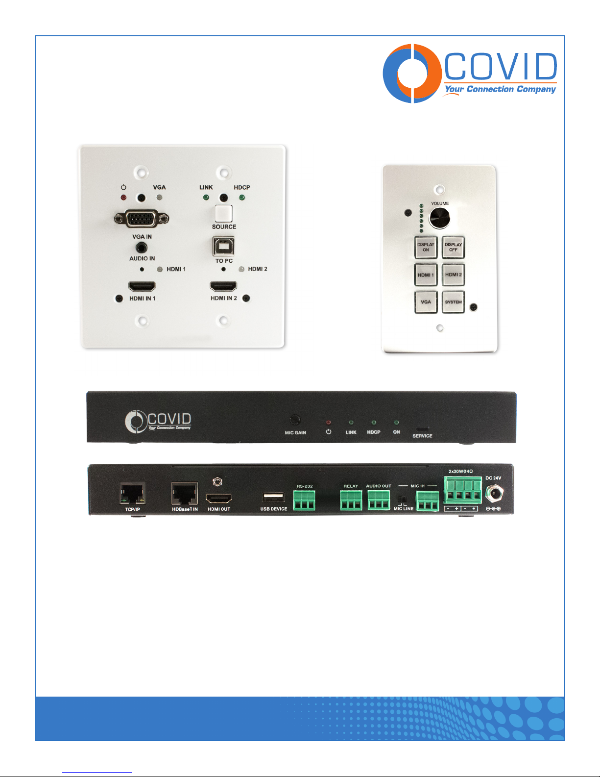
Optional Smart Keypad Control
Front View
Back View
All-in-One A/V Control System
HDBase-T Smart System - P31H-01
1723 W. 4th Street Tempe Arizona 85281
P: 800.638.6104 | F: 480.966.6728 | E: sales@covid.com | www.covid.com
Page 2

USER MANUAL
Table of Contents
1. Introduction ................................................................ 2
2. Features .................................................................. 2
3. Package Contents ............................................................ 2
4. Technical Specifications .......................................................3-4
5. Operation Controls & Functions ................................................... 5
5.1. Transmitter Front and Rear Panel ............................................5-6
5.2. Receiver Front and Rear Panel ..............................................7-8
5.3 Control Panel Front and Rear Panel ............................................ 9
6. Connection Diagram..........................................................10
7. Web Server - LOGIN .........................................................11
8. Web Server - MAIN ........................................................12-13
9. Web Server - CONTROL .....................................................14-16
10. Web Server - INPUT/OUTPUT ................................................17-18
11. Web Server - SYSTEM .....................................................19-20
12. System on/Off Subroutine .....................................................21
13. Display On/Off Subroutine ..................................................... 22
14. System Reset ............................................................. 23
Warranty ................................................................... 24
Safety Information ............................................................. 24
Thank you for purchasing this product
For optimum performance and safety, please read these instructions care¬fully before connecting, operating,
or adjusting this product. Please keep this manual for future reference.
Surge protection device recommended
This product contains sensitive electri¬cal components that may be damaged by electrical spikes, surges,
electric shock, lightning strikes, etc. In order to protect and extend the life of your equipment, use of surge
protection systems is highly recommended.
HDBase-T Smart System - P31H-01
1723 W. 4th Street Tempe Arizona 85281
P: 800.638.6104 | F: 480.966.6728 | E: sales@covid.com | www.covid.com
Page 1
Page 3

USER MANUAL
1. Introduction
The P31H-01 is an intelligent, all-in-one AV system. It offers video extension of two HDMI and one VGA signal,
video switching, system control, and analog audio amplification. Uncompressed video, audio, and control can
be transmitted up to 230ft/70m, using HDBaseT™ technology over a single cat 6/6a cable. For convenience,
the P31H-01 can be controlled by its web GUI or an optional control panel: KP-100.
2. Features
• HDMI 1.4b, HDCP 2.2 and HDCP 1.4 compliant.
• Video resolutions up to 4K2K@30Hz, 1080p@120Hz, and 1080P 3D@60Hz.
• Audio up to 7.1 channels of High Definition audio pass through
(LPCM, Dolby TrueHD, and DTS-HD Master Audio).
• HDBaseT™ over a single cat 6/6a cable up to 230ft/70m distance.
• Support multi-VESA Standard VGA formats input.
• Supports balanced MIC input.
• 2x30watts@4 ohms amplifier output.
• Supports interactive display USB pass-through.
• Supports Web GUI control.
• Two relay outputs.
• Supports RS-232 control.
3. Package Contents
• 1 x 2-Gang Extender Transmitter
• 1 x HDMI Extender Receiver
• 1 x 24V3.75A DC Power Supply
• 1 x User Manual
• 2 x Mounting ears
HDBase-T Smart System - P31H-01
1723 W. 4th Street Tempe Arizona 85281
P: 800.638.6104 | F: 480.966.6728 | E: sales@covid.com | www.covid.com
Page 2
Page 4
USER MANUAL
4. Technical Specifications
Technical
HDMI Compliance HDMI 1.4b
HDCP Compliance HDCP 2.2 and HDCP 1.4
Video Bandwidth 10.2 Gbps
Video Resolution up to 4K2K@30Hz,1080P@120Hz, and 1080P 3D@60Hz
Color Space RGB, YCbCr 4:4:4, YCbCr 4:2:2
Color Depth 8-bit,10-bit, 12-bit
HDMI Audio Formats
(Pass-through)
ESD Protection Human body model — ±8kV (air-gap discharge) & ±4kV (contact discharge)
Connections
Transmitter
Inputs 2x HDMI IN Type A [19-pin female]
Outputs 1x HDBaseT Out [RJ45]
Receiver
Inputs 1x HDBaseT In [RJ45]
Outputs 1x HDMI OUT Type A [19-pin female]
LPCM 2/5.1/7.1CH, Dolby Digital, DTS 5.1, Dolby Digital+, Dolby TrueHD, DTSHD Master Audio, Dolby Atmos, DTS:X
1x VGA [DB15 VGA female]
1x AUDIO IN [3.5mm Stereo Mini-jack]
1x RS-232/POWER [RJ45]
1x MIC IN [Screw Terminal]
1x USB [USB A TYPE]
1x TCP/IP[RJ45]
1x RS-232 [Screw Terminal]
1x RELAY [Screw Terminal]
1x AUDIO OUT [Screw Terminal]
1x 2x30watts@4 ohms amplifier output [Screw Terminal]
HDBase-T Smart System - P31H-01
1723 W. 4th Street Tempe Arizona 85281
P: 800.638.6104 | F: 480.966.6728 | E: sales@covid.com | www.covid.com
Page 3
Page 5
USER MANUAL
Mechanical
Housing Metal Enclosure
Color Black, White
Dimensions Transmitter:
115.9mm [W] x 114.3mm [D] x 38.7mm [H]
Receiver:
250mm [W] x 104mm [D] x 30mm [H]
Control Panel:
69.9mm [W] x 114.3mm [D] x 22.2mm [H]
Weight Transmitter: 305g
Receiver: 790g
Control Panel: 180g
Power Supply Input: AC100 - 240V 50/60Hz
Output: DC 24V/3.75A (US/EU standards, CE/FCC/UL certified)
Power Consumption 75W (Max)
Operation Temperature 32 - 104°F / 0 - 40°C
Storage temperature -4 - 140°F / -20 - 60°C
Relative Humidity 20 - 90% RH (no condensation)
HDBase-T Smart System - P31H-01
1723 W. 4th Street Tempe Arizona 85281
P: 800.638.6104 | F: 480.966.6728 | E: sales@covid.com | www.covid.com
Page 4
Page 6
USER MANUAL
5. Operation Controls and Functions
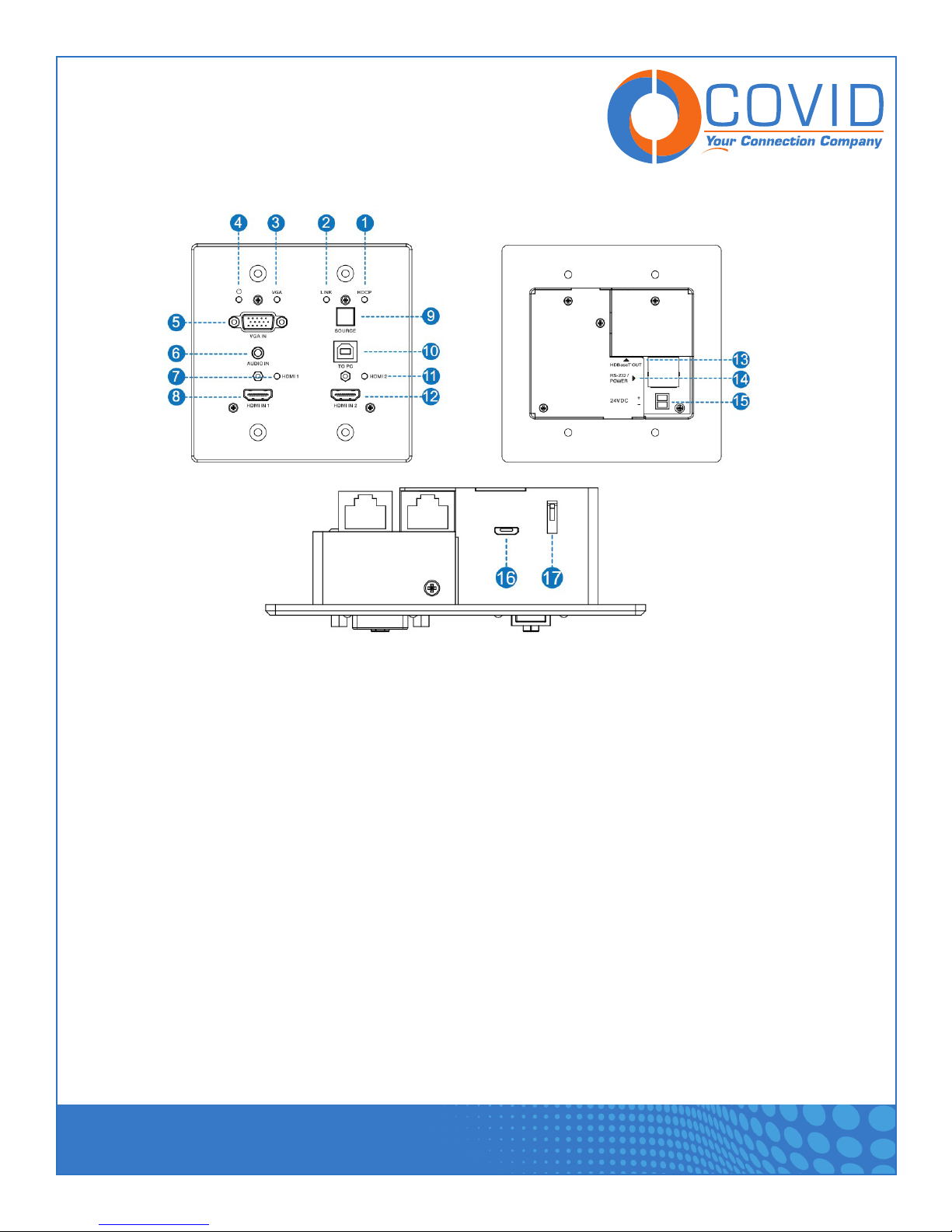
5.1 Transmitter Front and Rear Panel
1. HDCP LED: HDCP compliance indicator.
• OFF: HDMI input is not carrying HDCP content
• ON: HDMI input is carrying HDCP content
2. LINK LED: HDBaseT Link status indicator.
• OFF: No Link
• GREEN: Link successful
• Blink GREEN: Link abnormal
3. VGA LED: VGA signal indicator.
• OFF: There is no +5V HPD or VGA signal detected on input
• FLASHING: +5V HPD or VGA signal is detected
• GREEN: VGA is active input and VGA signal is detected
4. POWER LED: System power indicator.
5. VGA IN: Connect with VGA source.
HDBase-T Smart System - P31H-01
1723 W. 4th Street Tempe Arizona 85281
P: 800.638.6104 | F: 480.966.6728 | E: sales@covid.com | www.covid.com
Page 5
Page 7

USER MANUAL
6. ADUIO IN: Connect with external audio source for VGA signal.
7. HDMI 1 LED: HDMI 1 signal indicator.
• OFF: There is no +5V HPD or HDMI signal detected on input
• FLASHING: +5V HPD or HDMI signal is detected
• GREEN: HDMI is active input and HDMI signal is detected
8. HDMI 1 IN: Connects to HDMI source device.
9. SOURCE: Press it to select one source.
10. TO PC: Connect PC to transmit USB control signal from the Receiver USB device in.
11. HDMI 2 LED: HDMI 2 signal indicator.
• OFF: There is no +5V HPD or HDMI signal detected on input
• FLASHING: +5V HPD or HDMI signal is detected
• GREEN: HDMI is active input and HDMI signal is detected
12. HDMI 2 IN: Connects to HDMI source device.
13. HDBaseT OUT: Connects to HDBaseT Receiver with a Cat 6/6a cable.
14. RS-232/POWER: Connects to Control Panel via Cat 5e/6/6a cable.
15. 24VDC (OPTIONAL): Connects 24V/1A adaptor to AC wall outlet for power supply.
16. MICRO-USB: For firmware update.
17. DIP SWITCH: Select upgrade type.
HDBase-T Smart System - P31H-01
1723 W. 4th Street Tempe Arizona 85281
P: 800.638.6104 | F: 480.966.6728 | E: sales@covid.com | www.covid.com
Page 6
Page 8
USER MANUAL
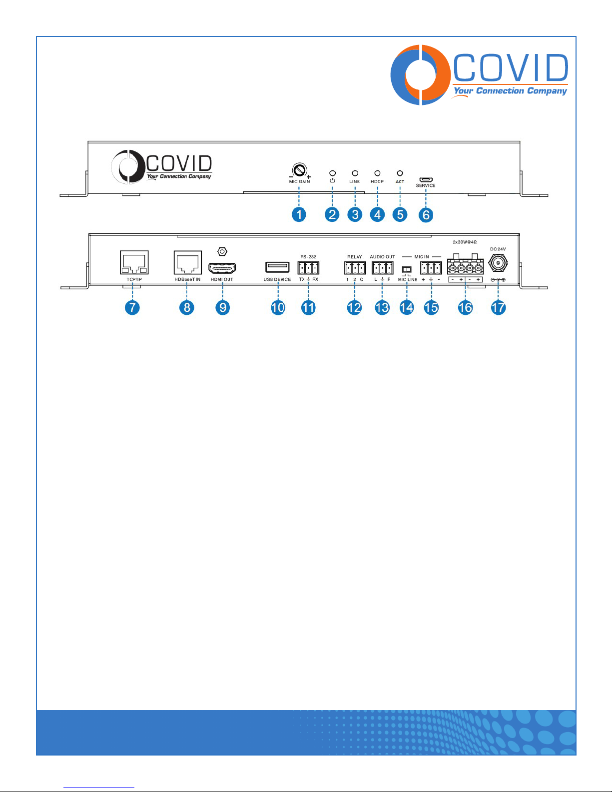
5.2 Receiver Front and Rear Panel
1. MIC GAIN: Set the MIC input gain.
2. POWER LED: System power indicator.
3. LINK LED: HDBaseT Link status indicator.
• OFF: No Link
• GREEN: Link successful
• Blink GREEN: Link abnormal
4. HDCP LED: HDCP compliance indicator.
• OFF: HDMI input is not carrying HDCP content
• ON: HDMI input is carrying HDCP content
5. ACT: System work indicator.
• OFF: System standby or power off
• Blink GREEN: System working
6. SERVICE: For firmware update.
7. TCP/IP: Connect to a PC access to the WEB GUI for system configuration.
8. HDBaset IN: Connects to HDBaseT Transmitter with a Cat 6/6a cable.
9. HDMI OUT: Connects to a HDMI display device.
HDBase-T Smart System - P31H-01
1723 W. 4th Street Tempe Arizona 85281
P: 800.638.6104 | F: 480.966.6728 | E: sales@covid.com | www.covid.com
Page 7
Page 9

USER MANUAL
10. USB DEVICE: Connect to an interactive display.
11. RS-232: RS232 control for the display.
12. RELAY: To control the projector screen rise and fall.
13. AUDIO OUT: Connect to a speaker.
14. MIC LINE SWITCH:
• When the switch is set to “MIC”, the microphone input is used to connect a dynamic microphone.
• When the switch is set to “LINE”, the microphone input is used for connecting a line level audio
source or wireless microphone output.
15. MIC IN: Using Phoenix terminal cable to connect microphone input.
16. 2X30 watts @ 4Ω / 2X15 watts @ 8Ω: Connect to speaker out.
17. DC 24V: Connect 24V/3.75A adaptor to AC wall outlet for power supply.
HDBase-T Smart System - P31H-01
1723 W. 4th Street Tempe Arizona 85281
P: 800.638.6104 | F: 480.966.6728 | E: sales@covid.com | www.covid.com
Page 8
Page 10

USER MANUAL
5.3 Control Panel Front and Rear Panel
1. VOLUME Knob and Volume level indicator: Adjust amplifier output volume.
• Clockwise adjustment to increase the volume.
• Counter-clockwise adjustment to decrease the volume.
2. DISPLAY ON: Run Display ON Subroutine, see section 13.
3. HDMI 1: Select HDMI 1 signal as input source.
4. VGA: Select VGA signal as input source.
5. DISPLAY OFF: Run Display OFF Subroutine, see section 13
6. HDMI 2: Select HDMI 2 signal as input source.
7. SYSTEM: Long-press this button for 3 seconds to run System ON/OFF Subroutine, see section 12
8. RS-232/POWER: Connects to Transmitter via CAT5e/6/7 cable.
HDBase-T Smart System - P31H-01
1723 W. 4th Street Tempe Arizona 85281
P: 800.638.6104 | F: 480.966.6728 | E: sales@covid.com | www.covid.com
Page 9
Page 11

USER MANUAL
6. Connection Diagram
HDBase-T Smart System - P31H-01
1723 W. 4th Street Tempe Arizona 85281
P: 800.638.6104 | F: 480.966.6728 | E: sales@covid.com | www.covid.com
Page 10
Page 12

USER MANUAL
7. Web Server - Login
1.
The default IP to login to the web server is 192.168.2.100.
2.
The default Username and Password for the admin are both “admin”.
The default Username and Password for the user are both “user”. The user login
limits the amount of functions accessible.
HDBase-T Smart System - P31H-01
1723 W. 4th Street Tempe Arizona 85281
P: 800.638.6104 | F: 480.966.6728 | E: sales@covid.com | www.covid.com
Page 11
Page 13

USER MANUAL
8. Web Server - MAIN
1.
Shows the status of the input signals.
Green = connected and active signal
Blue = connected but not active signal
Red = not connected
HDBase-T Smart System - P31H-01
1723 W. 4th Street Tempe Arizona 85281
P: 800.638.6104 | F: 480.966.6728 | E: sales@covid.com | www.covid.com
Page 12
Page 14

USER MANUAL
2.
Volume controls for the amplifier and audio extractor outputs. Adjust the slider to increase or decrease the
amplifier output or the volume of the extractor output. Toggle the Mute setting to silence the amplifier and
audio extractor outputs. Mute does not silence the audio on the HDMI output line.
3.
System – runs the system on/off subroutine when toggled, see section 12.
Connection Status – indicates if the connection to the web server is good.
Display – Runs the display on/off subroutine when toggled, see section 13
Output Mute – when on, turns off the video output. Does not mute audio.
HDBase-T Smart System - P31H-01
1723 W. 4th Street Tempe Arizona 85281
P: 800.638.6104 | F: 480.966.6728 | E: sales@covid.com | www.covid.com
Page 13
Page 15

USER MANUAL
9. Web Server - CONTROL
1.
When enabled, the display on/off subroutine will run every time the system on/off subroutine runs,
see section 12
2.
When enabled, the system will turn off when no signals are actively connected to the plate for a programma-
ble amount of time. See No Activity Timeout in the INPUT/CONTROL section.
HDBase-T Smart System - P31H-01
1723 W. 4th Street Tempe Arizona 85281
P: 800.638.6104 | F: 480.966.6728 | E: sales@covid.com | www.covid.com
Page 14
Page 16

USER MANUAL
3.
Sets the relays to either be triggered with the display on/off subroutine or the system on/off subroutine, see
section 12 and 13.
4.
Sets the amount of time that the relay contacts will stay closed.
5.
Sets the RS232 communication settings for the RS232 port.
6.
RS232 On Command – Sends out the data when Display On subroutine is called.
RS232 Off Command – Sends out the data when Display Off subroutine is called.
HDBase-T Smart System - P31H-01
1723 W. 4th Street Tempe Arizona 85281
P: 800.638.6104 | F: 480.966.6728 | E: sales@covid.com | www.covid.com
Page 15
Page 17

USER MANUAL
CR + LF – Appends a carriage return and line feed character to the end of the input strings as they
are sent out.
The commands can be input as hexadecimal numbers, if the Hex checkbox is marked.
7.
After any change is made, the settings must be saved by pressing the Save button.
Wait for the popup window to close automatically before continuing to make further changes, while it saves.
HDBase-T Smart System - P31H-01
1723 W. 4th Street Tempe Arizona 85281
P: 800.638.6104 | F: 480.966.6728 | E: sales@covid.com | www.covid.com
Page 16
Page 18

USER MANUAL
10. Web Server – INPUT/OUTPUT
1.
Sets how the switcher plate will change between input signals.
2.
Sets the priority to use when the switch mode is set to priority mode.
1 is the highest priority and 3 is the lowest.
HDBase-T Smart System - P31H-01
1723 W. 4th Street Tempe Arizona 85281
P: 800.638.6104 | F: 480.966.6728 | E: sales@covid.com | www.covid.com
Page 17
Page 19

USER MANUAL
3.
Sets the amount of time it will take for the unit to turn itself off when there is no input signal detected.
It is only used when Auto System button is set to enabled on the Control tab.
4.
Sets how many seconds the audio from the amp is delayed.
5.
HDMI EDID – when set to Internal, the EDID communicated to the source is the one stored in the
P31H-01’s memory.
EDID – the name of the current EDID.
EDID Update – upload a .bin file to change what EDID is stored in the P31H-01’s memory that is used
when EDID is set to internal.
HDBase-T Smart System - P31H-01
1723 W. 4th Street Tempe Arizona 85281
P: 800.638.6104 | F: 480.966.6728 | E: sales@covid.com | www.covid.com
Page 18
Page 20

USER MANUAL
11. Web Server – SYSTEM
1.
The network settings of the P31H-01 system
HDBase-T Smart System - P31H-01
1723 W. 4th Street Tempe Arizona 85281
P: 800.638.6104 | F: 480.966.6728 | E: sales@covid.com | www.covid.com
Page 19
Page 21

USER MANUAL
2.
This is the user-assigned label that appears at the top of the web interface.
3.
The user and admin password settings
4.
Upload new firmware versions and see current ones installed. This can update the firmware of the control
panel and the receiver box, not the two-gang transmitter. To update the firmware of the two-gang switcher,
use the USB port on the plate.
HDBase-T Smart System - P31H-01
1723 W. 4th Street Tempe Arizona 85281
P: 800.638.6104 | F: 480.966.6728 | E: sales@covid.com | www.covid.com
Page 20
Page 22

USER MANUAL
12. SYSTEM ON/OFF SUBROUTINE
HDBase-T Smart System - P31H-01
1723 W. 4th Street Tempe Arizona 85281
P: 800.638.6104 | F: 480.966.6728 | E: sales@covid.com | www.covid.com
Page 21
Page 23

USER MANUAL
13. DISPLAY ON/OFF SUBROUTINE
HDBase-T Smart System - P31H-01
1723 W. 4th Street Tempe Arizona 85281
P: 800.638.6104 | F: 480.966.6728 | E: sales@covid.com | www.covid.com
Page 22
Page 24

USER MANUAL
14. System Reset
To perform a system reset hold the source button (labeled 9) for 20 seconds until the HDCP light flashes
three times. When the system is reset, user settings will return to their default values this includes:
passwords, room label, switching mode, IP address, etc.
HDBase-T Smart System - P31H-01
1723 W. 4th Street Tempe Arizona 85281
P: 800.638.6104 | F: 480.966.6728 | E: sales@covid.com | www.covid.com
Page 23
Page 25

USER MANUAL
!
!
Warranty
Parts and labor warranty time is three year and from the date of original shipment. This warranty shall be
void if a serial number has been removed from the product.
Upon determination of a legitimate defect covered by this warranty and at COVID’s sole discretion, user
should bear the transport cost during the warranty.
If product is out of warranty then repair charge is required. Out of warranty repairs will only be made after
cost has been approved by Customers and proper financial arrangements are made. Customer must cover
round trip shipment expenses.
Safety Information
To reduce the risk of electric shock, do not expose this product to rain or moisture.
Do not modify the wall plug. Doing so will void the warranty and safety features.
If the wall plug does not fit into your local power socket, hire an electrician to replace your
!
obsolete socket.
This equipment should be installed near the socket outlet and the device should be easily
accessible in the case it requires disconnection.
HDBase-T Smart System - P31H-01
1723 W. 4th Street Tempe Arizona 85281
P: 800.638.6104 | F: 480.966.6728 | E: sales@covid.com | www.covid.com
Page 24
 Loading...