

Page 1

1723 West 4th Street / Tempe, AZ 85281
phone (480) 966-2221 / fax (480) 966-6728
toll free (800) 638-6104
inter net: www.covid.com
©2002 Covid, Inc. All Rights Reserved.
CVD 5206
CVD 5216
Composite / S-Video
Switchers
User’s Manual
Page 2

CVD 5206
6 Input, 1 Output
S-Video Switcher
CVD 5216
6 Input, 1 Output
Composite Video Switcher
A Simple Solution for Switching Several
Video Sources to One Display
DISCLAIMER
The information contained in this docu-
ment is subject to change without
notice.
Covid, Inc. makes no warranty of any
kind with regard to this material.
This document contains proprietary in-
formation that is protected by copy-
right. All rights are reserved. No part of
this document may be reproduced or
distributed in any form or by any
means without prior written consent of
Covid, Inc.
Page 3
CVD 5206
CVD 5216
23
Contents
Introduction 2
Panel Descriptions 3
Front Panel 3
Rear Panel 4
Operational Setup 5
User Instructions 7
Keypad Control 7
Selecting A Scan Mode Preset 9
Set Output Gain Level 9
Set Clamp Level 9
RF Remote 10
Battery Replacement 10
RS232 Interface Program 11
RS232 Description 11
RS232 Commands 12
RS232 Messages 15
RS232 Control Using a PC, Example 18
General Specifications 20
CVD 5206 20
CVD 5216 21
1
Page 4

Introduction
Thank you for purchasing a CVD 5206/5216 video
switcher. Covid’s CVD 5206/5216 provides a simple solution for switching several video source inputs to one
display. It can be controlled via the Front Panel Keypad,
RS232, or RF remote*. Some of the features of the CVD
5206/5216 video switchers include:
• 6 Inputs on BNC Female(5216) or 4-pin Mini-DIN fe-
male connectors(5206).
• 1 Output on BNC Female(5216)connector or 4-pin
Mini-DIN female connector(5206).
• Front Panel Keypad
• Auto Scan
• Scan Sequencing
• 9 Programmable Scan Sequences
• Programmable Video Hold Times from 1 second to 4
minutes.
• Video Blanking
• Buffered Outputs
• 150 MHz Bandwidth
• 7 Segment Channel Readout Display
• RS232 Controllable
• RF Remote Control*
• Vertical Interval Switching+
• Electronic Gain Adjustment
• Black Level / Sync Tip Selectable
*Purchase Option
+Inputs must be synchronized.
2 22
Page 5
21
Panel Descriptions
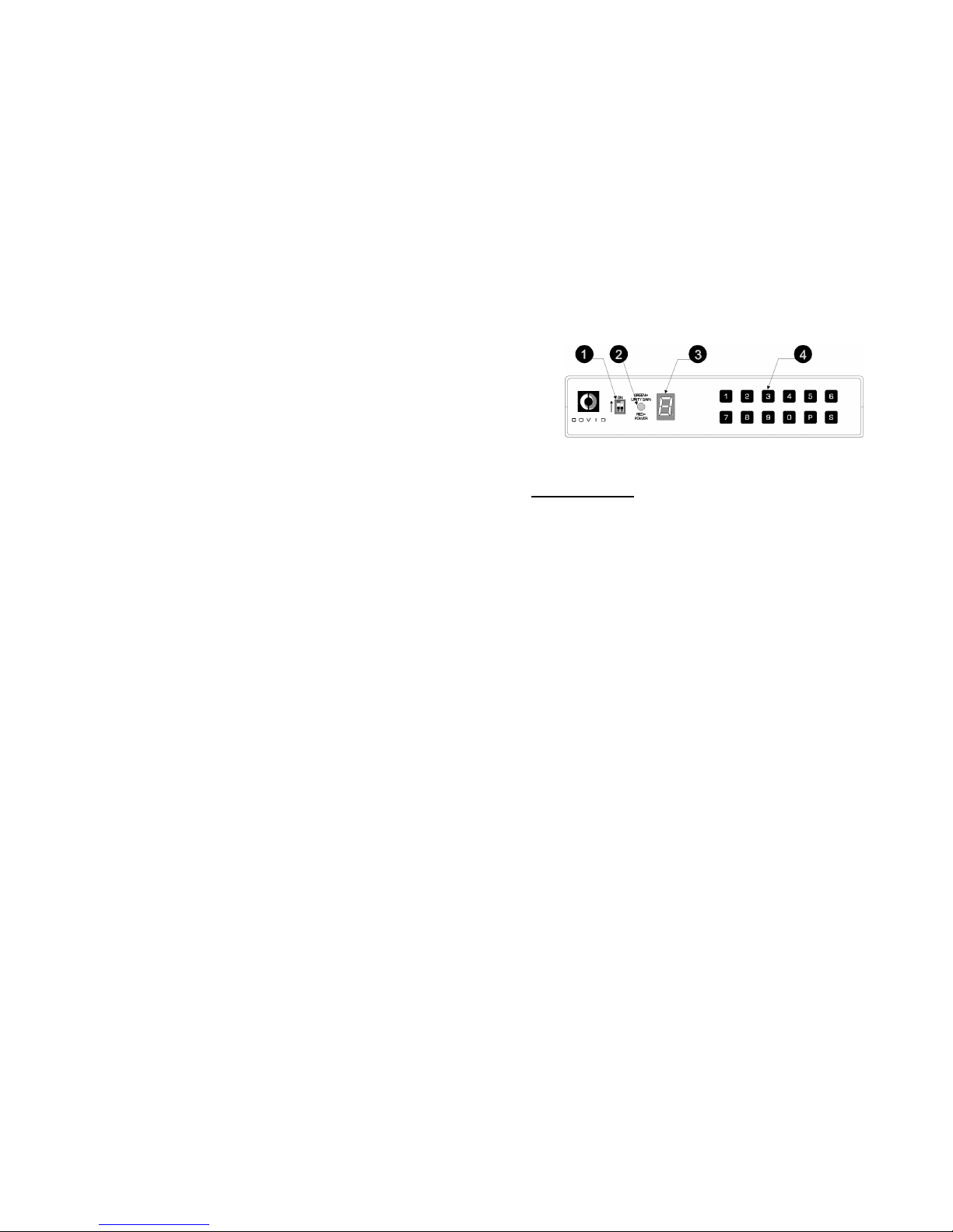
FRONT PANEL LAYOUT
FRONT PANEL
1. RF ID BITS: The dip switches set the ID for the RF
remote.
2. POWER ON: The LED turns red when power is ap-
plied to the unit and green if gain is set to Unity gain.
3. SEVEN SEGMENT DISPLAY: Displays the current
input being viewed and aids in programming scan se-
quences.
4. KEYPAD: The 12 keys are used to switch inputs and
program the unit.
3
Page 6

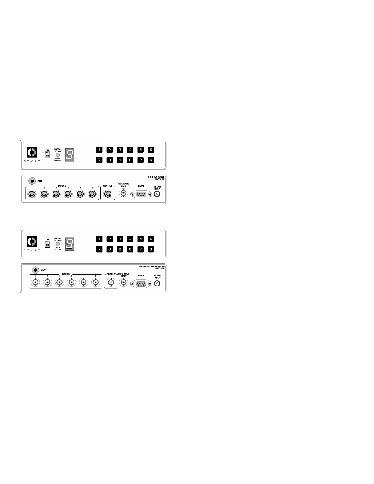
Panel Descriptions
CVD 5216 REAR PANEL LAYOUT
CVD 5206 REAR PANEL LAYOUT
REAR PANEL
1. ANTENNA IN: Accepts the antenna for the RF remote op-
tion.
2. INPUTS: Six BNC Female ( CVD 5216 ), or six 4 pin miniDIN ( CVD 5206 ) inputs available for video sources.
3. OUTPUT: One BNC Female ( CVD 5216 ), or one 4 pin
mini-DIN ( CVD 5206 ) to connect to a display.
4. REFERENCE INPUT: Provided for synchronized switching
during the reference input sync pulse.
5. RS232 INPUT: DB-9 connector provided for controlling the
unit using RS232 commands.
6. AC INPUT: Accepts 12 VAC from the Wall Mount AC input.
4
General Specifications
CVD 5216 6 IN, 1 OUT COMPOSITE VIDEO SWITCHER
INPUT:
Signal: Composite Video
Connectors: (7) BNC Female
Video Impedance: 75 Ohms
Signal Level: 0.5 – 2.0 Vpp
OUTPUT:
Connectors: (1) BNC Female
Video Impedance: 75 Ohms
Signal Level: 0.6 – 1.5 Vpp
Bandwidth: 130 MHz
Differential Gain: <0.1%
Differential Phase: <0.5 Degrees
CONTROL:
Front Panel Keypad
RS232 Controllable
RF Remote* (Optional)
Connector: 9-pin D-Sub, Female
DISPLAYS:
Power On Indicator
Seven-Segment Channel Readout
PHYSICAL SPECIFICATIONS
DIMENSIONS: 1U High, 1/2 Rack Wide
(in) 1.75 H x 8.50 W x 6.00 D
(cm) 4.45 H x 21.59 W x 15.24 D
ENCLOSURE: Aluminum, Black, Texture Finish
WEIGHT:
Net: 1.6 lbs. / 0.73 kg
POWER:
Input: 110 or 120 VAC Wall Mount,
12 VAC, 1A, UL
Dissipated: 3 Watts
21
Page 7

General Specifications
CVD 5206 6 IN, 1 OUT S-VIDEO SWITCHER
INPUT:
Signal: S-Video
Connectors: (6) 4-pin Mini-DIN Female
Video Impedance: 75 Ohms Y/C
Signal Level: 0.5 – 2.0 Vpp
OUTPUT:
Connectors: (1) 4-pin Mini-DIN Female
Video Impedance: 75 Ohms Y/C
Signal Level: Y: 0.5 – 1.5 Vpp
C: 143 mVpp – 429mVpp
Bandwidth: 130 MHz
Differential Gain: <0.1%
Differential Phase: <0.5 Degrees
CONTROL:
Front Panel Keypad
RS232 Controllable
RF Remote* (Optional)
Connector: 9-pin D-Sub, Female
DISPLAYS:
Power On Indicator
Seven-Segment Channel Readout
PHYSICAL SPECIFICATIONS
DIMENSIONS: 1U High, 1/2 Rack Wide
(in) 1.75 H x 8.50 W x 6.00 D
(cm) 4.45 H x 21.59 W x 15.24 D
ENCLOSURE: Aluminum, Black, Texture Finish
WEIGHT:
Net: 1.6 lbs. / 0.73 kg
POWER:
Input: 110 or 120 VAC Wall Mount,
12 VAC, 1A, UL
Dissipated: 3 Watts
20
Operational Setup
Turn off all equipment before connecting or removing cable connections.
1. Connect up to six video source signals to the desired inputs.
2. Connect the video output to a display.
3. If desired, connect a reference sync source signal
to the reference input.
4. To control the unit using a computer, the CVD
5206 / CVD 5216 RS232 port must be connected
to the PC’s serial port using a straight through serial cable.
5. Power up the unit and check power on LED indicator.
6. The Seven Segment Display should read ‘1’.
7. The unit is now operational. Switch inputs as desired using the front panel keypad, RS232, or the
RF remote.
5
Page 8

Typical Configuration
DSS RECEIVER
DVD PLAYER
DOCUMENT CAMERA
VHS RECORDER
RS232 CONTROLLER
CAMERA
VIDEOCONFERENCING CODEC
TELEVISION MONITOR
6 19
Page 9

RS232 Control Using a PC, Example
In this example, a terminal emulation program on a PC was used to
control the CVD 52x6. The settings for the PC were as follows:
9600 BAUD RATE
NO PARITY BIT
1 START BIT
8 DATA BITS
1 STOP BIT
FLOW CONTROL Xon/Xoff
ECHO CHARACTERS LOCALLY OFF
Below is a sample of the communication from the PC to the CVD
52x6. An example of how to store a scan sequence is also shown
below. The boldface typing is not present when controlling the unit in
this manner. It is used here to illustrate what the command accomplishes.
>SW3$
( connect video input 3 to output, $ = good command )
[SWITCH VIDEO 3]
>PG2$
( start program scan sequence into location 2 )
[PROGRAM USER MODE 2]
[PROGRAM MODE ON]
>T003$
( set time between switches to 3 seconds )
[STORE TIME]
>V1$
( start at video input 1, step 1 of sequence )
[STORE VIDEO]
>V3$
( next show video input 3, step 2 of sequence )
[STORE VIDEO]
>V5$
( next show video input 5, step 3 of sequence )
[STORE VIDEO]
>PG2$
( end program mode, saves into memory )
[PROGRAM USER MODE 2]
[PROGR AM MODE OFF/DONE]
>PS$
( program status, shows scan sequences stored in memory )
[PROGRAM STATUS]
PRESET TIME SEQUENCE STEPS
0: 3 1 2 3 4 5 6 0 0 8
1:
2: 3 1 3 5 3
3:
4:
5:
6:
7:
8:
9:
>SC1$
( start scan mode )
[SCAN MODE 1]
>SC1$
( end scan mode )
[END SCAN MODE]
>
18
User Instructions
When the unit is first powered on, the seven-segment
display shows the number ‘1’. This indicates that input 1
is switched to the output.
Keypad Control
Switching Video
To select an input, simply press the number representing
the input to be displayed. Press the [0] button for a video
blank.
Store Video Sequence
To store a scan sequence, press [P], the display should
blink ‘P’. Press a button between 1 – 9, this represents
the program sequence being stored. Next, the unit needs
to know the hold time between switching inputs represented in seconds. The time can be from 1 to 255 seconds (approximately 4 minutes). To enter a time of 5
seconds, for example, press [0], [0], [5]. Next the unit
wants the sequence of the inputs to switch, for example,
the odd inputs, press [1], [3], and [5]. To end program
mode and store the sequence, press [P]. The display
will return to the input selected before programming began. Nine different sequences can be stored. Eight input
choices can be selected per sequence.
Scan Mode
To scan a stored sequence, press [S], then press a button between 0 – 9 representing the sequence desired.
To end scan mode, press any button. Pressing a number
between 0– 6 will end scan mode and switch to that particular input.
7
Page 10

Pressing [S], [P], or [9] will end scan mode and the last
input showing will remain selected.
Storing a Scan Sequence Into Memory, An Example
Say we want to store a scan sequence into memory
scanning the even inputs only leaving each input connected for 30 seconds. First we need to select a preset
to store the sequence. In this example, let’s use preset 1.
Press [P], then press [1]. The display should blink ‘P’.
Next we must enter the time in 3 digits, in this example,
we chose 30 seconds. Therefore, we must enter 0 – 3 –
0. Press [0], the display will show ‘0’, then return to a
blinking ‘P’. Now press [3], the display will show ‘3’, then
return to a blinking ‘P’. Next press [0], the display will
show ‘0’ then return to a blinking ‘P’. The time of 30 seconds has been saved.
Next, we need to enter the video sequence. In this example, we chose the even inputs. Press [2], then [4], then
[6]. The display should behave as it did for entering the
time. Finally, to end program mode and store the sequence, press [P]. The display will stop blinking ‘P’ and
return to the input that is currently selected. By pressing
[S] or [9] will also end program mode.
The sequence is now stored in preset position ‘1’, and is
ready to be placed in scan mode. When this position is
chosen to be scanned, it will show input 2 f o r 30 seconds
then switch to input 4, wait 30 seconds, and so on. After
showing input 6 for 30 seconds, it will roll around back to
input 2, and then continue on until scan mode is stoppe d.
8
String Message ‘Software Version *.*’
• Applies after the version command. Displays the current
software version of the internal firmware.
String Message ‘Program Status’
• Applies after the status command.
• Displays a chart of the stored scan sequences.
PRESET TIME SEQUENCE STEPS
0 3 1 2 3 4 5 6 0 0 8
1 30 2 4 6 3
The TIME is represented in seconds. SEQUENCE represents the
input switch sequence. STEPS shows how many inputs have been
selected for that particular sequence.
In this Program Status Display, PRESET 1 will show input 2 for 30
seconds, then switch the input 4. After another 30 seconds, it will
switch to input 6. After another 30 seconds, it will recycle back to input 2 and continue through the sequence until SC AN Mode is
stopped.
String Message ‘Gain Setting *’
• Sent after a gain setting command.
• Signifies the gain level setting shown by the *.
String Message ‘Black Level’
• Sent after the Black Level Select command.
• Notifies the user that the reference voltage is now at Black
Level.
String Message ‘Sync Tip’
• Sent after a Sync Tip Clamp Select Command.
• Notifies the user that the reference voltage is now sync tip
clamped.
String Message ‘Auto Sense *’
• Sent after the Auto Sense Command.
• Notifies the user that Auto Sense is ON or OFF.
17
Page 11

String Message ‘Store Time’
• Applies only when in program mode.
• Notifies that a legal video hold time has been entered into
memory.
String Message ‘Error! Number Must be Less than 6’
• Applies when in program mode.
• Applies if entering a time over 200 seconds.
• Maximum number of seconds allowed is 255 seconds,
therefore any number entered after the 2, must be less than
6.
String Message ‘Store Video’
• Applies when in program mode.
• Applies after a legal time has been entered.
• Notifies that the video selected has been stored into mem-
ory.
String Message ‘Error! Not in Program Mode’
Applies when not in program mode and a time to be stored into
memory is entered.
String Message ‘Program Mode OFF/DONE’
• Applies after program mode has been completed.
String Message ‘Scan Mode *’
• Applies after a preset scan sequence has been selected.
The preset chosen is designated by the *.
String Message ‘Preset Not Programmed’
• Applies when selecting to scan a preset that has not yet
been stored.
String Message ‘End SCAN Mode’
• Applies while in scan mode, then a switch to an input or
ending scan mode has been requested.
16
Selecting A Scan Mode Preset
To put the unit into Scan Mode, press [S] then the preset you wish to
scan. Since we just programmed Preset 1, let’s scan preset 1. Press
[S], the display will blink ‘-‘ then press [1]. The unit will then start the
sequence programmed in the previous example. In this case, input 2
will start, show for 30 seconds, then switch to input 4 and continues.
To end scan mode, press any key. If you press [S], [P], or [9], scan
mode ends and stays with the input that was last showing. If you
press a numbered key the unit will end scan mode and switch to the
input selected.
Set Output Gain Level
Upon power up, the unit adjusts the video output voltage level to
unity gain automatically. This can be changed in increments of .1 V
by adjusting the gain. To change the output voltage level, press [9].
The letter ‘L’ appears on the seven-segment display. Press a button
from [0] – [9], this adjusts the gain from 0.6 Vpp at 0, to 1.5Vpp at 9.
The LED will turn green at unity gain, 1 Vpp.
Set Clamp Level
To set the reference voltage level to Black Level, press [P], then [0],
a blinking ‘H’ will appear in the display. Press [0] again. To set the
reference voltage level to Sync Tip, press [P], then [0], then press
[1].
Auto Scan
To turn on the Auto Scan feature press [S], then press [S] again.
The display should show a solid dash, if there are no video inputs
present. The Auto Scan feature will scan the inputs looking for a
video sync starting at input 1. Once a sync is found, the switcher will
automatically show the input found. When the sync is removed, the
unit will start scanning again, starting over at input 1. For example, if
input 3 was found, input 3 will be switched to the output. If there is
an input present on input 4 and an input becomes present on input
2, when input 3 is removed, the next video found will be input 2, not
input 4. Input 1 takes highest priority and input 6 takes the lowest.
9
Page 12

RF Remote
The RF remote makes it convenient to switch inputs at
distances up to 75 feet. The buttons on the remote behave in the same manner as the Front Panel keypad buttons.
To use your remote, make sure the DIP switch ID bits on
both the CVD 5206/5216 and the CVD 550R match.
They are both defaulted to be ‘0’ ‘0’ from the factory.
A slide switch on the side of the remote is provided to
greatly extend battery life when the remote is not in use.
Set the slide switch to the ON position. Now, press a button. The display on the CVD 5206/5216 should change
to match the button pressed.
The DIP switch ID bits are provided in case you have
multiple units and need to control them separately or all
at once using the RF remote. The RF remote must be
opened to change the ID bits. The ID bits on the CVD
5206/5216 are externally accessible. When not using the
remote, set the slide switch to the OFF position.
RF Remote Battery Replacement
To replace the battery, the case must be opened. Press
on the tab of the battery holder to pop out the opposite
end of the battery. Carefully remove. Carefully slide one
end of the new battery under the tab. Gently press the
battery into the socket. The battery is a 3V lithium coin
type battery, CR2032 size.
10
RS232 Messages
The CVD 5206/5216 RS232 routine sends feedback messages to
the user. Each character typed is echoed back to the terminal. Some
of the messages provide helpful information when using the CVD
5206/5216. Messages are enclosed in square brackets. [ ]
Character Message ‘?’ -- Unknown Command
• Applies after an unrecognized character or bad command.
• Sent after an [Enter] key or a full command buffer.
Character Message ‘$’ -- Good Command
• Applies after a recognized command.
• Sent after an [Enter] key or a full command buffer.
After a good/bad command, the unit will return a prompt on a new
line. After this message, the PC command must be reentered from
the beginning.
String Message ‘Switch Video *’
• Applies after a complete command has been recognized.
• Sent after an [Enter] key and a valid command.
• A switch has been made to the input designated by the *.
String Message ‘Video Showing is *’
• Sent after a status command.
• Tells the user what input is current being shown.
String Message ‘Program User Mode *’
• Sent after a program command.
• Entering program mode for storing a user preset designated
by the *.
String Message ‘Program Mode ON’
• Sent after a program command.
• Entering program mode for storing a user preset.
15
Page 13

8. Software Version
This command displays the version of the internal software.
FORMAT:
PC COMMAND: VS(Enter)
HEX EQUIVALENT: [56][53][0D]
9. Gain Setting
This command sets the gain level of the output signal.
FORMAT:
PC COMMAND: GN(level)(Enter)
HEX EQUIVALENT: [47][4E](level)[0D]
Format for (level): ASCII characters 0-9, Hex Equivalents [30]-[39]
10. Black Level Clamp Select
This command sets the clamp select to black level.
FORMAT:
PC COMMAND: LVB(Enter)
HEX EQUIVALENT: [4C][56][42][0D]
11. Sync Tip Clamp Select
This command set the clamp select to the sync tip level.
FORMAT:
PC COMMAND: LVS(Enter)
HEX EQUIVALENT: [4C][56][53][0D]
12. Auto Scan
This command sets the unit to auto scan mode.
FORMAT:
PC COMMAND: AS(on/off)(Enter)
HEX EQUIVALENT: [41][53][on/off][0D]
Format for (on/off): ASCII characters 0-1, Hex Equivalents [30]-[31]
Where ‘1’ is on and ‘0’ is off.
14
RS232 Interface Program
RS232 Description
The RS232 port on the CVD 5206/5216 is a DB-9 pin female connector. The interface cable is a standard
straight through DB-9 cable with a male end and a female end. Communication from a PC to the CVD
5206/5216 is possible provided the PC has terminal
emulation software such as HyperTerminal for Windows
95/98/2000.
CVD 5206/5216 DB-9 Female Connector Pinout
PIN 2 Transmit, Output from CVD5206/5216
( Receive on terminal side )
PIN 3 Receive, Input from CVD5206/5216
( Transmit on terminal side )
PIN 5 Ground
ALL OTHER PINS NOT CONNECTED
Communication Parameters
ASYNCHRONOUS
SERIAL
9600 BAUD RATE
NO PARITY BIT
1 START BIT
8 DATA BITS
1 STOP BIT
11
Page 14

RS232 Commands
1. Select Video Input
This command switches the selected input to the output.
FORMAT:
PC COMMAND: SW(input)(Enter)
HEX EQUIVALENT: [53][57][input][0D]
Format for (input): ASCII characters 0 – 6,
Hex Equivalents [30] – [36].
Choose ‘0’ for video blanking. ASCII characters 1-6 represent the
input.
2. Program Preset
This command starts program mode for storing a sequence.
FORMAT:
PC COMMAND: PG(preset)(Enter)
HEX EQUIVALENT: [50][47][preset][0D]
Format for (preset): ASCII characters 1-9, Hex Equivalents [31] –
[39]
3. Time Set
This command sets the time interval between video switches for the
selected preset. This command is only accepted when in program
mode.
FORMAT:
PC COMMAND: T(digit1)(digit2)(digit3)(Enter)
HEX EQUIVALENT: [54][digit1][digit2][digit3][0D]
Format for (digit1): ASCII characters 0-2, Hex Equivalents [30]-[32]
Format for (digit2) and (digit3): ASCII characters 0-9, Hex Equiva-
lents [30]-[39], if (digit1) is less than 2, otherwise,
ASCII characters 0-5, Hex Equivalents [30]-[35]
12
4. Store Video Input
This command selects the input sequence to store in memory. This
command is only accepted when in program mode and the time setting has been entered.
FORMAT:
PC COMMAND: V(input)(Enter)
HEX EQUIVALENT: [56][input][0D]
Format for (input): ASCII characters 0-6, Hex Equivalents [30]-[36].
Choose 0, for video blank.
5. Scan Mode
This command sets the unit to scan mode.
FORMAT:
PC COMMAND: SC(set)(Enter)
HEX EQUIVALENT: [53][43][set][0D]
Format for (set): ASCII characters 0-9, Hex Equivalents [30]-[39]
6. Status Update
This command reports what video input is currently selected.
FORMAT:
PC COMMAND: ST(Enter)
HEX EQUIVALENT: [53][54][0D]
7. Program Status
This command reports the status of the program settings, includes
time, video sequence, and number of sequences.
FORMAT:
PC COMMAND: PS(Enter)
HEX EQUIVALENT: [50][53][0D]
13
 Loading...