

Page 1
version 2.0/2015
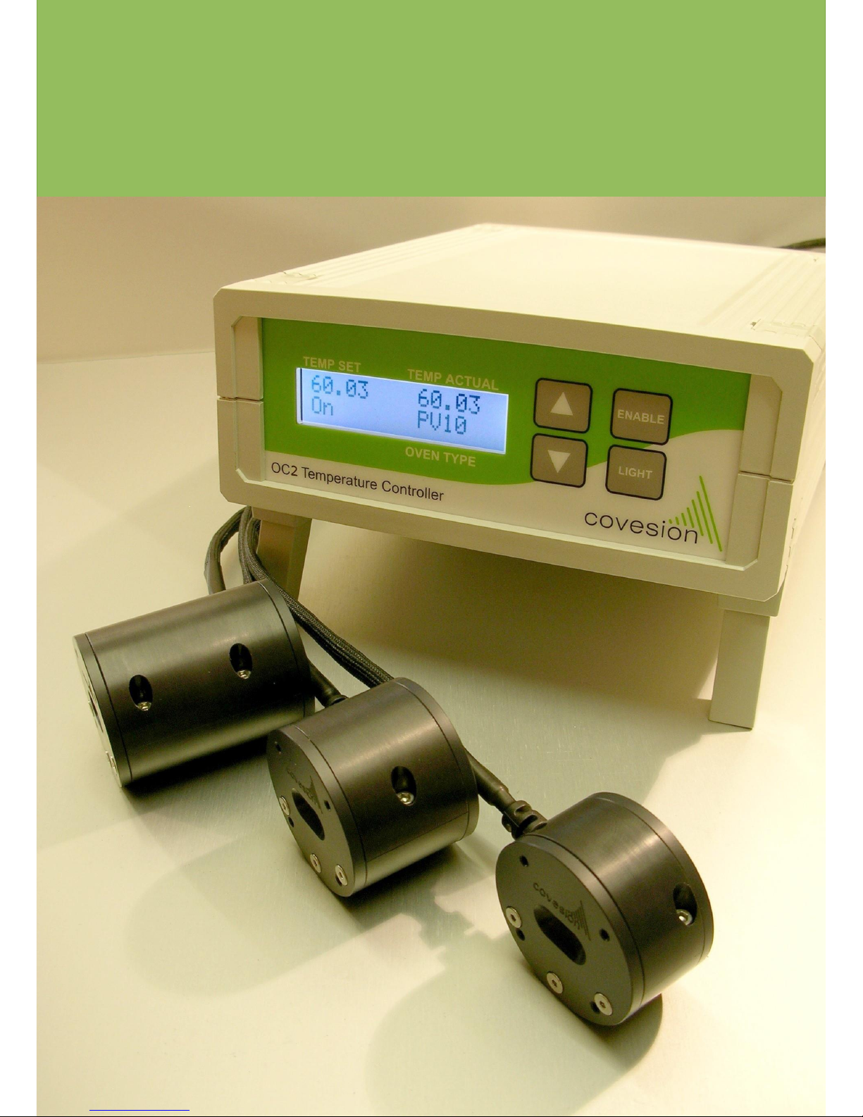
PPLN Clip, Oven and
Temperature Controller
User Guidelines
Page 2
Covesion offers several components which allow complete wavelength conversion solutions to be
constructed. The PPLN Clip, in which PPLN crystals are mounted, is designed to allow easy
handling and mounting of the crystal within the oven. The PPLN Oven permits operation of the
PPLN crystal at elevated temperature, allowing temperature tuning and minimisation of
photorefractive damage. The OC2 Temperature Controller is designed to offer optimum
temperature control of the PPLN crystal within the oven. The following document describes the
recommended operational procedures for the various components.
PPLN Clip
Covesion’s PPLN crystals are supplied mounted in clips, consisting of a clip body, an ITO coated
glass spacer, and the clip springs. The design of the clip ensures that the crystal is held in place
precisely and as such can simply be mounted in a PPLN oven. Under no circumstance should the
user attempt to remove the crystal from the clip. If unmounted crystals are required, then these
can be obtained directly from Covesion Ltd.
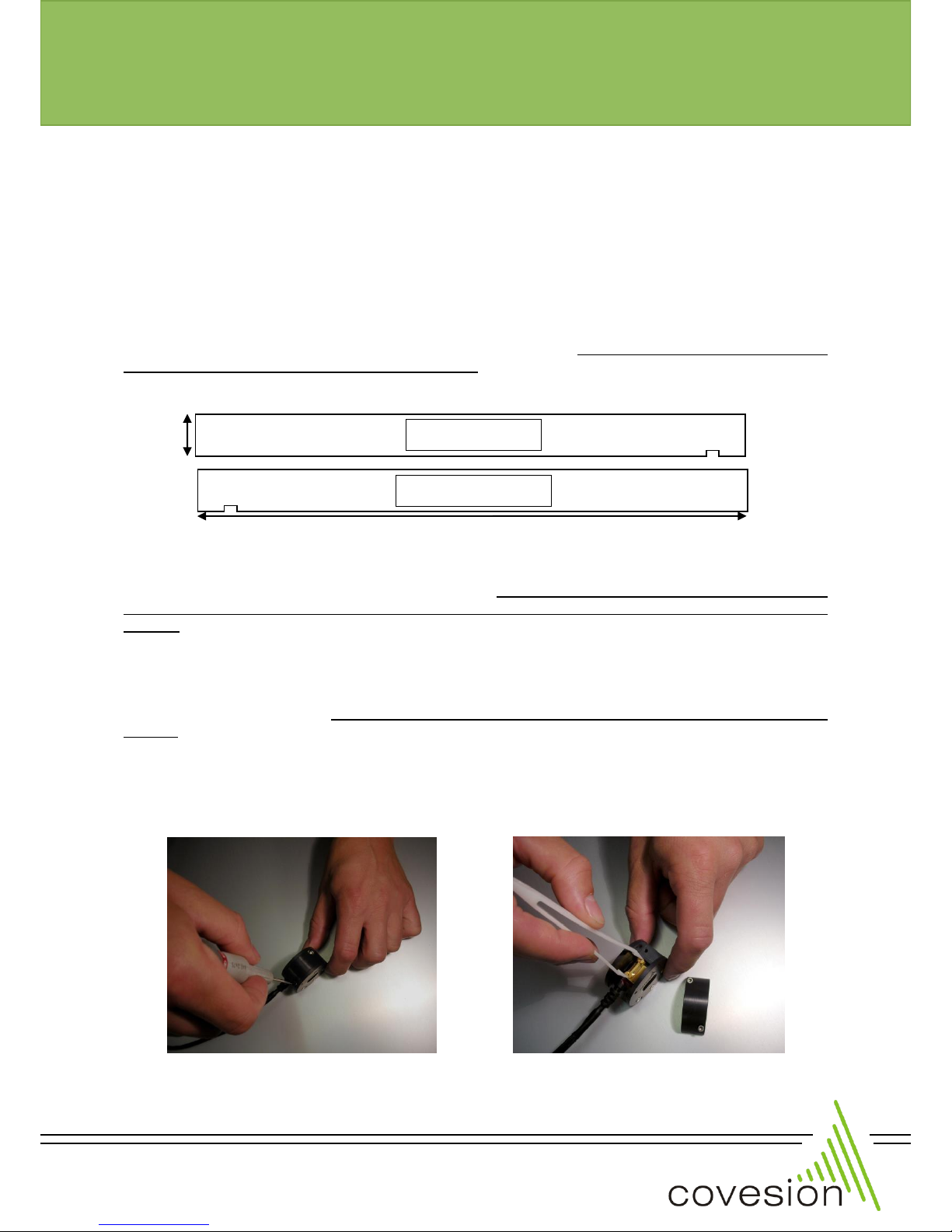
The crystals are marked with an alignment groove on underneath, see the diagram above. For
mounted 10, 20 and 40mm crystals, the serial number is scribed on the side of the clip and the
crystal alignment mark is also on the same side. In the case of the 1mm crystals this can be
obscured by the clip, therefore please note the serial number is scribed on the input facet side of
the clip. The gratings within a crystal increase in period the closer they are to the alignment
groove, i.e. period increases from left to right with respect to the input facet.
Users must take care not to mark the optical facets of a PPLN crystal during handling. If the optical
facet does become contaminated during use, then it can be wiped with a cotton bud soaked in
Isopropanol (IPA), although care must be taken not to damage antireflection coatings that are
present.
PPLN Oven
Covesion’s PPLN oven is designed for optimum operation of PPLN crystals at elevated
temperatures, and also offers a convenient and accurate method of mounting and aligning optical
crystals within an optical train.
INPUT FACET
10mm
OUTPUT FACET
0.5mm
or
1.0mm
web: www.covesion.com fax: +44 (0)8709 289 714
Figure 1. Oven top removal
Figure 2. PPLN clip installation
version 2.0/2015
version 1.0/2010
Page 3
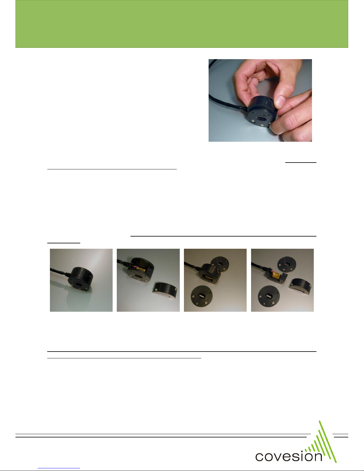
The oven top is removable using a 2mm hex driver to
take out the two retaining bolts (or four in the case of
the PV40). Then slide the top in the vertical direction to
remove the insulation and expose the heater (shown in
figure 1). The PPLN Clip sits on top of the heater,
locating on the dowel pins. When installing a PPLN Clip
ensure that it is safely located on the dowels, and is
sitting flat on the heater thus ensuring maximum heat
transfer to the clip (shown in figure 2).
When replacing the oven top, check that the recess for
the cable is on the correct side. It must also be ensured
that the spring pins, which push the clip onto the
heater, locate properly and will not be damaged as the
top is pushed on. As the oven top is relocated gently
push down towards the heater and tighten the retaining bolts (shown in figure 3). Do not use
excessive force to tighten the retaining bolts, otherwise thread damage may occur making it
impossible to fasten the oven top.
The PPLN oven can be operated in a number of different configurations, which through the
removal of insulation allows increased access to the PPLN crystal, however a decrease in oven
efficiency and stability will occur. The oven can be operated without the oven top in place, this can
be achieved by following the removal procedure outlined above. If greater access to the PPLN
crystals optical facets is required, then the end plates of the oven can be removed. The end plate
is removed by using a 1.5mm hex driver to take out the three retaining bolts. When replacing the
end plates, a similar degree of care must be taken as is associated with the removal and
replacement of the oven top, excessive force applied to the retaining bolts may result in damage
to the oven.
The oven can therefore be operated in one of four configurations; fully insulated (recommended),
top off only, end plates off only, and top and end plates off (all configurations shown in figure 4).
Care must be taken not to touch hot components when the PPLN oven is operated in any state
other than the recommend fully insulated configuration.
The PPLN oven utilises a 12-24V 3.6-15W element and a PT100 resistance temperature sensor,
which are cabled and connected to a plug for convenient connection to the OC2 temperature
controller. The variable power rating of the heater allows the heating characteristics to be tailored
to the specific oven being using, for example 3.6W produces stable operation for a fully insulated
PV10 (oven suitable for crystals of length 10mm and below) but for an uninsulated PV40 (oven
suitable for crystals of length 40mm and below) up to 15W may be required in order to produce
suitable operating parameters. The PPLN oven offers a stability of ±0.01C, when used with
web: www.covesion.com fax: +44 (0)8709 289 714
web: www.covesion.com fax: +44 (0)8709 289 714
Figure 3. Oven top replacement
Figure 4. Oven configurations
version 2.0/2015
Page 4
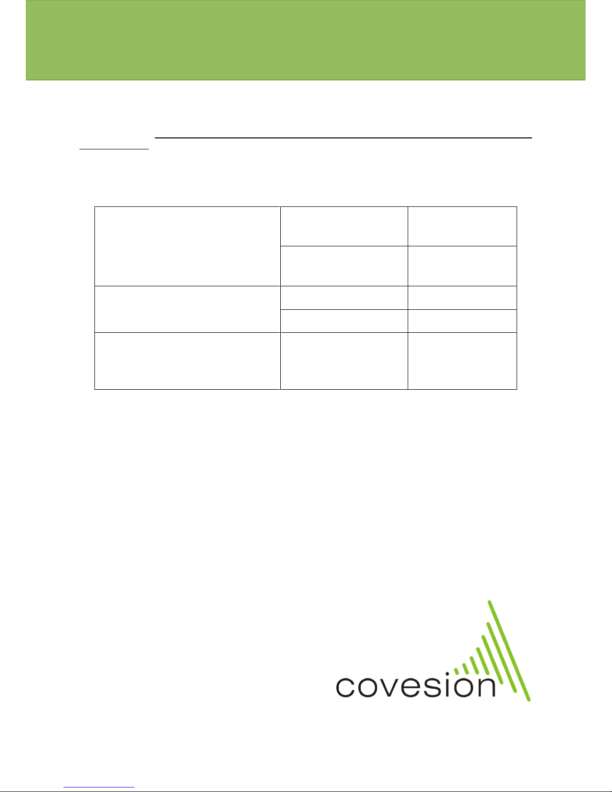
Covesion’s OC2 controller and when the oven is fully insulated. The maximum continuous
operating temperature for the PPLN oven is 210C, with an absolute maximum temperature rating
of 220C. The PPLN oven and any PPLN crystals should not be heated or cooled at a rate greater
than 25C/min. Exceeding maximum operating temperature or ramp rates can result in oven or
crystal damage. The OC2 controller is tuned such that it does not exceed the maximum ramp rate
when heating the PPLN clip, crystal and oven. The maximum OC2 set temperature is 200C.
Operating Parameters
Maximum Operating Temperature
PPLN Clip + Crystal
210C continuous
220C max
PPLN Oven
210C continuous
220C max
Maximum Ramp Rate
PPLN Clip + Crystal
25C/min
PPLN Oven
25C/min
Operating Voltage (Power)
PPLN Oven
12V (3.6W)
18V (8.3W)
24V (15W)
For more information, please contact us at:
tel:
+44 (0)1794 521 638
fax:
+44 (0)8709 289 714
email:
www.covesion.com
Covesion Ltd.
Unit A7
The Premier Centre
Premier Way
Romsey
SO51 9DG
United Kingdom
Registered in England No. 06338847
VAT No. 943 1896 00
Copyright © 2015 Covesion Ltd.
version 2.0/2015
 Loading...