

Page 1
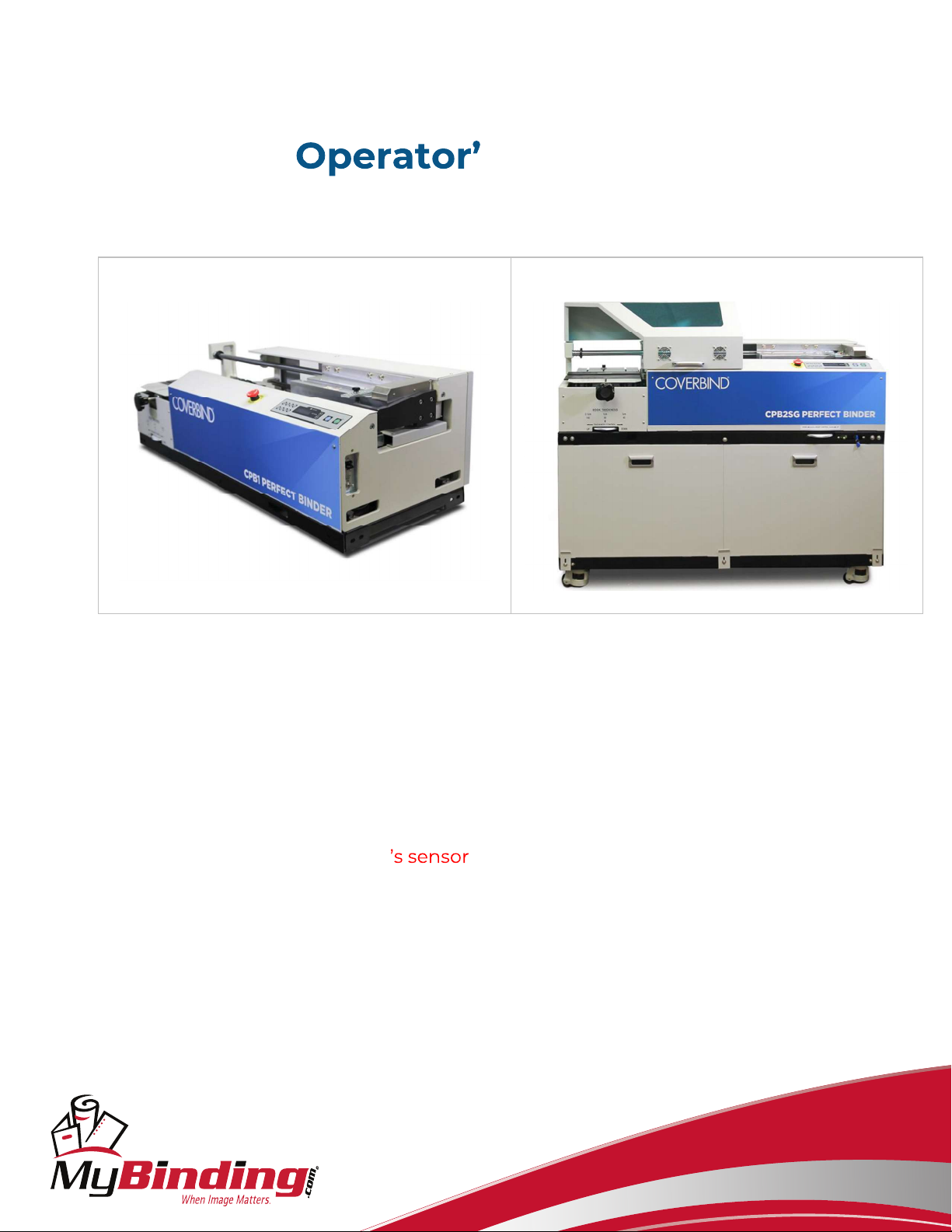
Coverbind Perfect Binding Systems
s Manual
Issue 1 November 1, 2021
CPB1 CPB2SG
This manual is for all versions of the Coverbind
Perfect Binders: Models CPB1, CPB2, and CPB2SG.
The CPB2 and CPB2SG sit on their own stand/cabinet which houses both the air
compressor and the dust extractor. To turn on the Dust Extractor, locate the toggle
switch on the front of the machine.
You can bypass the safety hood by using the supplied key(s) located near
the Dust Extractor switch.
mybinding.com
1-800-944-4573
Page 2

TABLE OF CONTENTS
GETTING STARTED
3
POWERING UP
8
CONTROL PANEL
8
SET UP
10
SET
TING
THE CLAMP LIMITER
11
ALIGN THE COVER
STOCK
13
BOOK THICKNESS WHEEL & NIPPE
R ADJUSTMENT KNOB
13
SIDE GLUE ADJUSTMENT
14
ADJUSTING BINDING STRENGTH
15
STARTING PRODUCTION
16
MAKING PADS
16
DRAINING GLUE
17
MAINTENANCE
18
DAILY MAINTENANCE
18
WEEKLY MAINTENANCE
18
TROUBLESHOOTING
19
UNEVEN OR INCONSISTENT SIDE GLUE
19
ADJUSTING SIDE GLUE BETWEEN HEAD AND FOOT OF BOOK
20
ADJUSTING SIDE GLUE ON OPERATOR AND NON
-
OPERATOR SIDES OF THE BOOK
20
PAGES NOT BINDING WELL
21
ROUGHING BLADE AND NOTCHING PINS ADJUSTMENT (
CPB
2SG model has a mill
22
UNEVEN CORNERS OF THE
BOOK SPINE
23
LEVELING THE NIPPER TABLE
23
MACHINE DOES NOT CYCLE
24
MACHINE BEEPS TWICE IN RAPID SUCCESSION AND DOES NOT CYCLE
24
CLAMP IS STUCK / ERROR MESSAGE
25
SCHEMATICS
26
blade)
Page 2 of 26
Page 3

GETTING STARTED
Congratulations on your purchase of THE COVERBIND CPB1, CPB2, or
CPB2SG. This machine will allow you to perfect bind any book up to 2-1/4 or
55mm thick.
CPB1 Model
Before removing the machine from the
shipping crate, have a table ready that
will support a minimum of 330 lbs. (150
kg).
Uncrate the machine and inspect it for
any damage that may have occurred
during transport.
Place the unit on the table; use of a lift
truck is recommended.
Be careful to avoid injury.
An optional stand is also available.
1. Remove the compressor from the box and stand on a solid surface.
Do not place the compressor in an enclosed area such as a cabinet
unless it is well ventilated. The air filter should already be installed on the
compressor but if not, locate it within the compressor box and install it
onto the fitting (FIG #1). Do not over tighten.
CPB2 and CPB2SG
Use a forklift to lift the machine off the
skid.
Keep the machine steady; it is very top
heavy.
Make sure all four wheels have the
stops in the up position before placing
it on flat level ground.
Once the machine has been moved to
its final position, lower the stops to
prevent the machine from rolling.
Some parts may already be installed.
The compressor shown may differ from the one which comes with the
machine. The compressor on the right does not need oil.
Page 3 of 26
Page 4
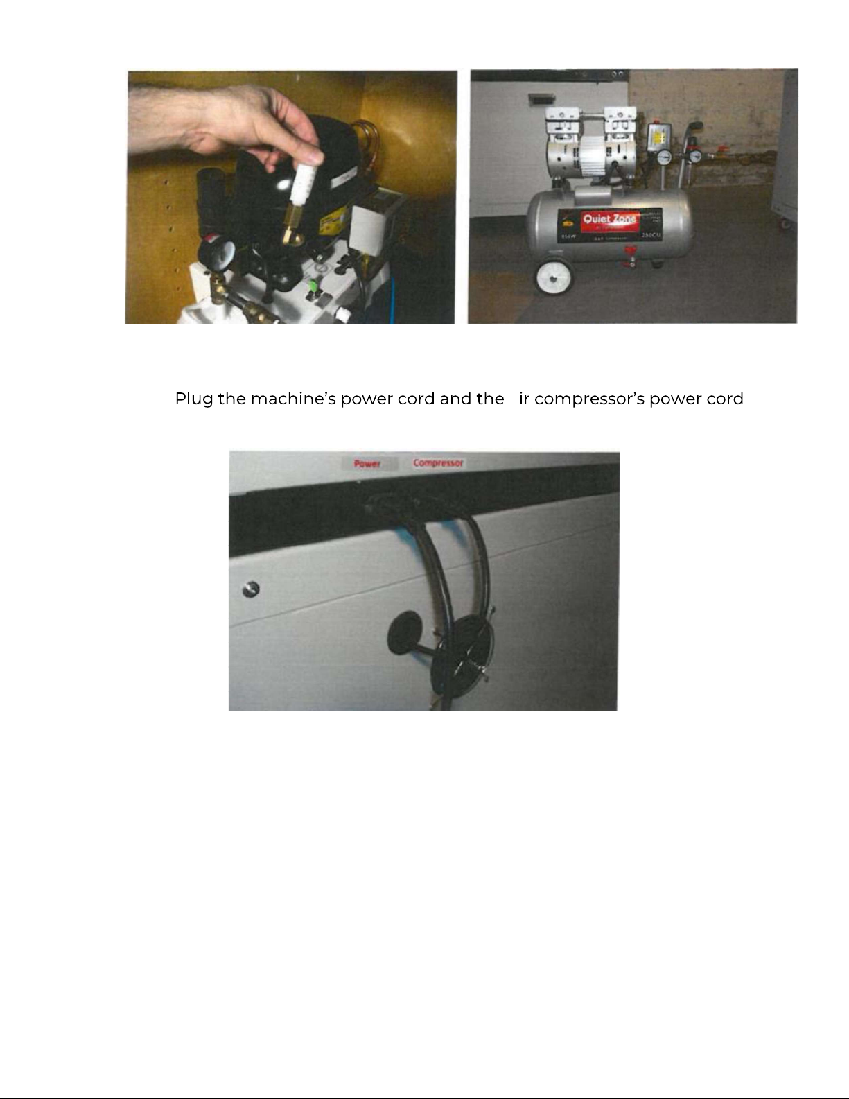
1.
into the back of the binder. (FIG #2)
Figure 1
a
Figure 2
2. Install the exhaust fan. The exhaust fan is already on the CPB2SG
models.
a. Start by attaching the connectors.
b. Press the connectors back into the exhaust box cavity along with
any slack of the cord and install the exhaust fan on the machine.
c. Flip the exhaust box power switch on (FIG #3).
Page 4 of 26
Page 5
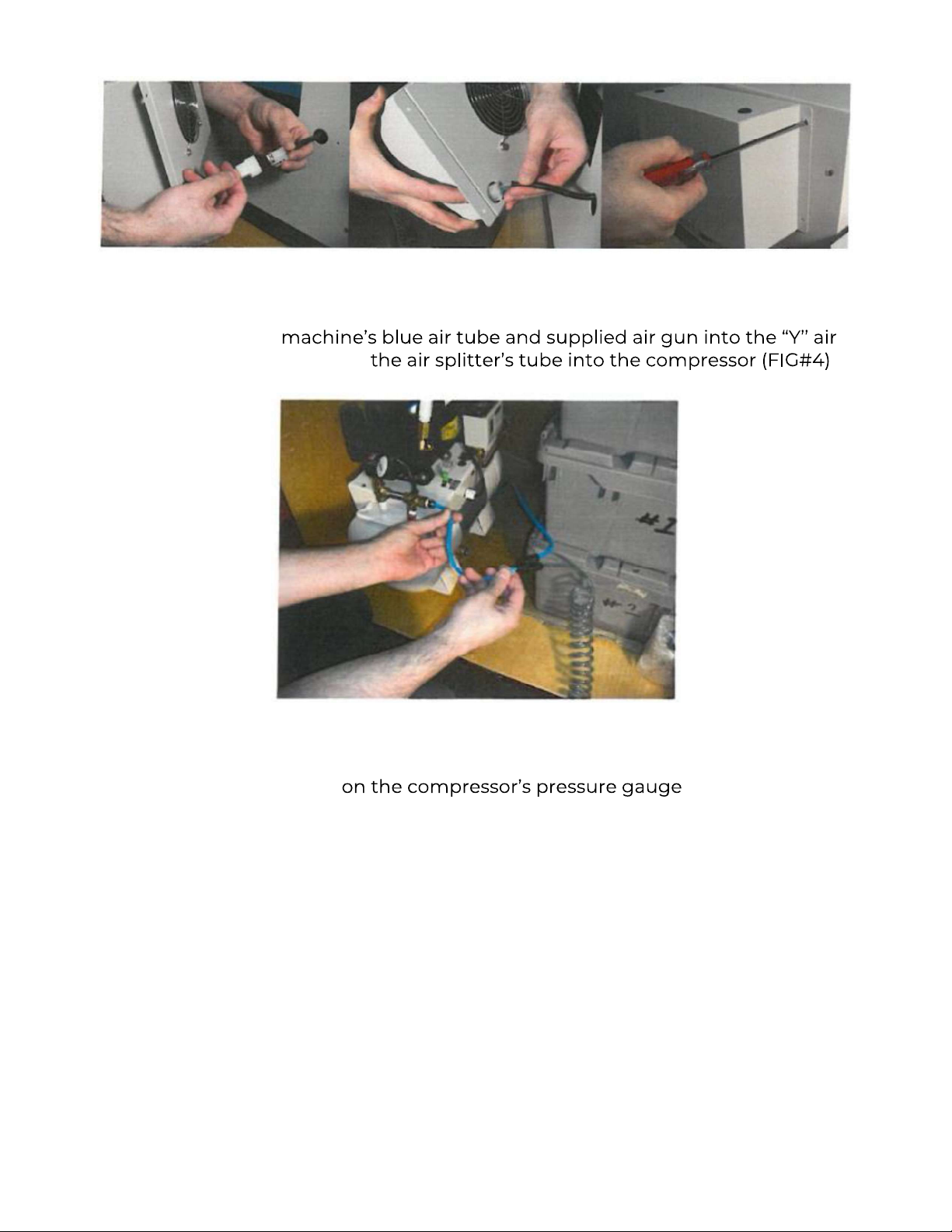
3. Plug the
splitter. Then plug .
Figure 4
Figure 3
4. Open the valve (FIG #5) and turn
the power switch to the on position. Make sure the bleed valve at the
bottom of the compressor is closed (not shown) (FIG #5 - Arrow).
Page 5 of 26
Page 6
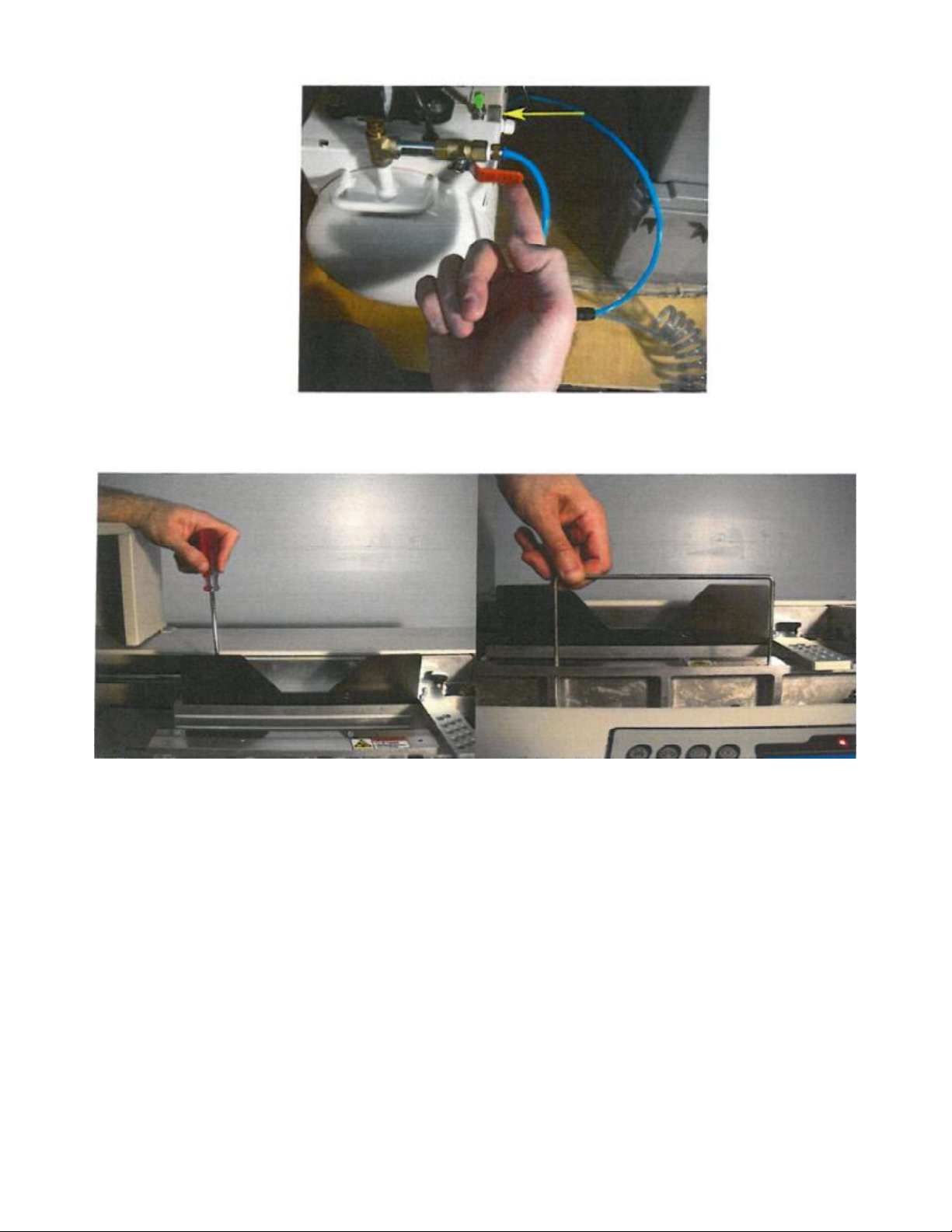
Figure 5
Figure 6 Figure 7
5. Attach the tall book guide to the top of the clamp. (FIG #6)
6. Install the book support. (FIG #7)
7. Install the rear table cover support behind the nipper table. (FIG #8)
Page 6 of 26
Page 7
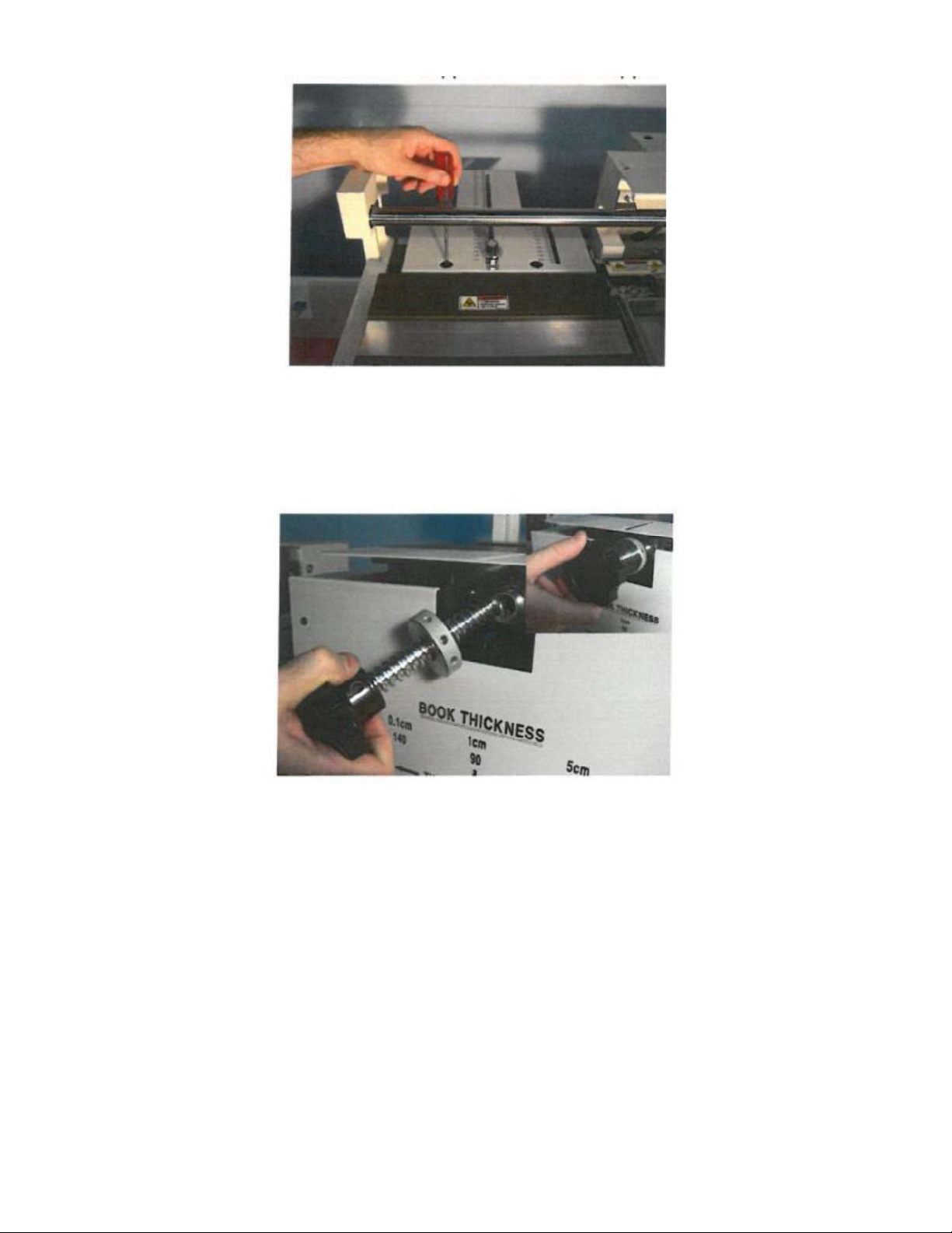
Figure 8
8. Screw in the nipper adjustment knob on the front of the nipper table.
(FIG #9)
Figure 9
Page 7 of 26
Page 8

POWERING UP
1. Have your electrician check that your incoming power is 220 volts, single
phase, 20-amp outlet. Have your electrician attach a plug onto the end of the
machines Power cord that matches your socket.
2. The power switch is located on the right side of the binder. Turn on the
machine and checked that the screen lights up along with a red LED
indicating the gluepot heater is on and working.
3. Make sure the Emergency stop button is in the up position. If not, give it a
gentle twist clockwise to release it.
CONTROL PANEL
The keypad controls the functions of the binder for operation, set up or
troubleshooting.
The following is a list of the control buttons and switches (FIG #10).
1. START: This will cycle the binder fully through the binding process. This
will not function unless there is a book in the clamp and cover stock on the
nipper table.
2. CLAMP: Opens and closes the clamp. Use this feature for setting the
clamp to the thickness of your book by utilizing the clamp limiter bar
(more on that later).
3. Green LED: The machine will not cycle until the glue has fully melted and
this LED is lit.
4. UP: Raises
5. DOWN:
6. Red LED: Indicates that the glue heater is on.
7. X: Clears the functions of the glue rollers. Drops and opens the nipper
table (if in the up and closed position), resets the batch count, and toggles
the padding feature on or off.
8. O: Stand by. Lowers the glue temperature to 130 and prevents any
function of the unit. **Also cycles the roughing motor/ sawblade if the
binder is in the SET UP Mode.
Page 8 of 26
Page 9
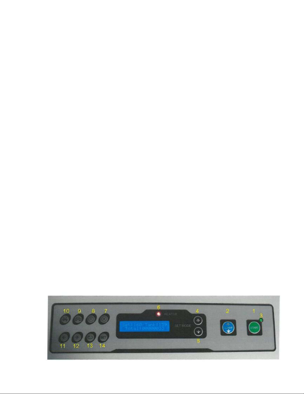
9. NIPPER CLOSE: Close the nipper table. Press X to open.
10. NIPPER UP: Raises the nipper table. Press X to open.
11. LEFT: Moves the clamp to the left.
12. RIGHT: Moves the clamp to the right.
13. CYCLE GLUE ROLLERS: Use when adding glue. Glue should be
approximately ¾ below the top of the gluepot.
14. SET: Pressing the UP or DOWN arrows on the 1st Screen changes the glue
pot temperature. The counter on this screen cannot be reset.
a. Press SET once for the padding Mode Screen.
b. Press X to toggle padding on or off.
c. Press SET again For the Finish Time (Nipper Table dwell time).
d. Use the UP or Down arrows to set the Nipper Table dwell time. If
Padding is on, each increment would add 10 Seconds. 15 would equal
150 seconds. If padding is off, 15 would equal 4 seconds.
e. Press SET a third time to get to the batch counter. This counter can be
reset using the X button.
f. Press SET once more to return to the main screen.
15. POWER SWITCH: Located on the right side of the machine.
16. TOGGLE SWITCH: Turns the roughing motor on or off. The toggle switch is
located below the Main power switch. Leave up for perfect binding or
down for making pads.
Page 9 of 26
Page 10
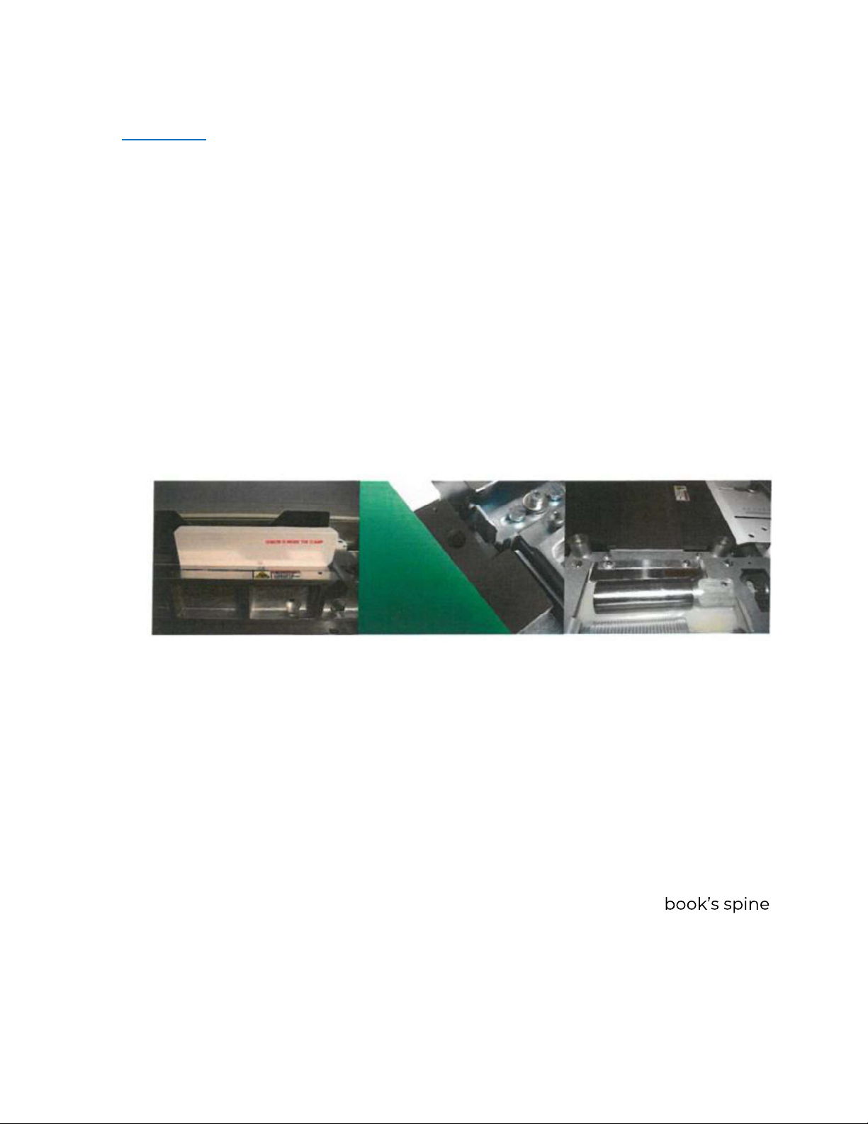
Figure 10
SET UP
1. Turn on the machine to warm up the glue pot. The machine will not cycle
until the glue has thoroughly melted. This should take approximately 45
minutes depending on glue and ambient air temperature.
During this time, the green LED will remain off and you cannot change the
setting from the control panel. The temperature will rise above the set value
then gradually lower to the set temperature.
2. When the machine is ready, the glue rollers will cycle, the machine will give 3
audible beeps and the green LED will light, indicating it is now ready for use.
3. At this time, you may adjust the temperature, if needed. We recommend 160
degrees centigrade (160°C = 320°F).
The machine will not cycle if the green LED is off (FIG #10, Item 3), without a
book in the clamp (FIG #11) or cover stock on the nipper table (FIG #12).
Figure 10 Figure 10
4. Put a cover in position on the nipper on the nipper table placing it square to
the right stops (FIG #12) (Round on the CPB2SG model) with the rear edge
tucked under the top stop guide. Loosen the top stop guide and adjust
accordingly, depending on the size of the book. The rear of the
will line up with the scored line in the nipper table. (FIG #13)
Page 10 of 26
Page 11
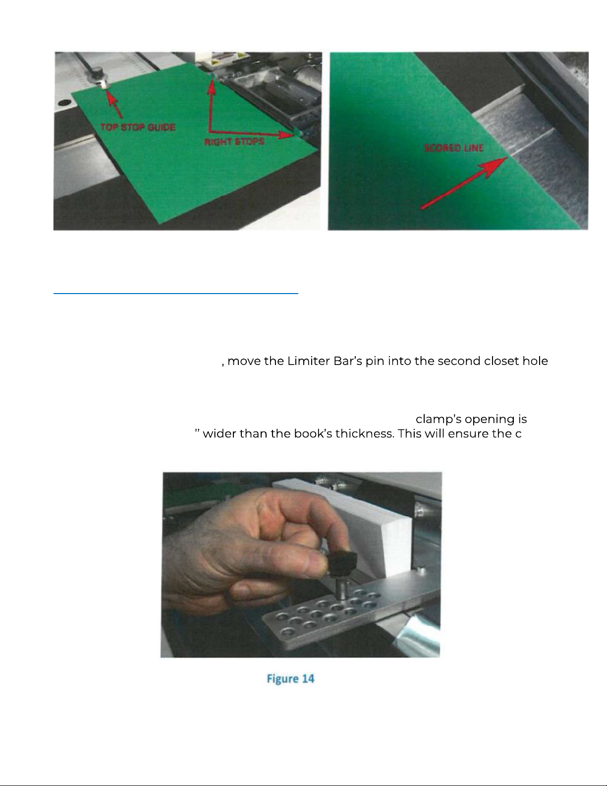
Figure 13
SETTING THE CLAMP LIMITER
1. Place the book block in the open clamp and jog it to the right, then press the
CLAMP button.
2. After the clamp closes
to the front, outside of the clamp. This will limit how wide the clamp opens so
placing books of the same thickness will be easier and quicker.
3. Press CLAMP again to open the clamp. Check that the
approximately 1/4 lamp
will not drag the book back after it has been bound. (FIG #14)
Page 11 of 26
Page 12

4. It is not necessary to continue to use the CLAMP button once the clamp
opening is set. Simply place the book inside the clamp and jog it down and to
the right so the pages are even.
5. Check that the cover is against both right stops and tucked under the back
stop. Make sure the toggle switch below the main power switch is up. Also
check that your Compressor is on and up to pressure and the pressure
position.
6. Keep your hand above the book to prevent any of the pages from
up. The Clamp may squeeze air out from between the pages as it closes.
7. Press START to cycle the machine.
8. Lift the book off the nipper table as the clamp retreats. Inspects the book for
Proper alignment of the cover, even corners of the spine and adequate glue
for both sides of the book.
9. Do not open the pages yet. Allow time for glue to cool and harden.
ALIGNING THE COVER STOCK
CAUTION: THE RIGHT STOPS ARE VERY HOT!
To adjust the cover left or right, loosen and move the right stops left or right using
Caution. Only loosen the hex screw in the center of each stop with the supplied
4mm T-handle Hex Key. Do not over tighten!
To adjust the Cover forward or back, loosen and adjust the Top Stop Guide (knob).
(FIG #13 &14) The CPB2SG model may have round eccentrics and when loosened
can be rotated which will move it left or right.
BOOK THICKNESS WHEEL & NIPPER ADJUSTMENT KNOB
The Book Thickness wheel (FIG #15) adjustment the upward pressure of the nipper
table to Help produce a flatter spine.
Page 12 of 26
Page 13
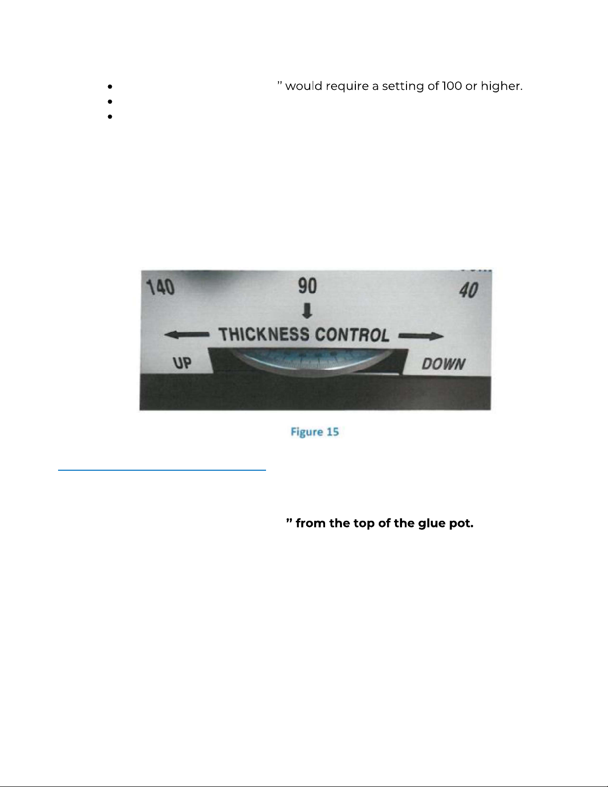
For thinner books, rotate toward left. For thicker books, rotate toward right.
Normally books under 1/4
Half inch books should be set at 70.
One inch or thicker should be set at 50 or slightly lower.
These are average settings. You may require more or less pressure depending on
your stock and covers. You may also make use of the Nipper Adjustment knob to
help produce square/sharper corners using the chart on the top plate of the nipper
table (FIG #9).
Note, setting the nipper adjustment knob too tight may cause some sheets of the
book to fold over. Simply open the nipper table further if this occurs. (FIG #9 and
#15)
SIDE GLUE ADJUSTMENT
CAUTION: THE GLUE POT & EVERYTHING ON IT IS VERY HOT!
Make sure the glue level is within 3/4 Add glue
chips as needed. Then try another book before making the following adjustments.
For more side glue on the non-operation side, loosen and move the Side Glue Wire
closer to the rear side of the book.
For less side glue, move it further away from the rear side of the book. (FIG #16)
If you have the CPB2SG model, use the two sheet metal metering plates to
adjust the amount of glue.
Page 13 of 26
Page 14
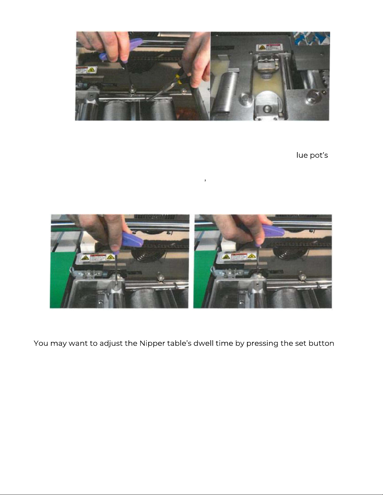
Figure 16
For more side glue on the operator side, you may need to adjust the g
metering roller down. Adjust the metering roller by loosening the set screw with
the supplied 3mm t-handle hex key then placing the tip of the hex key into any of
the holes in the nut located near the glue pot s drive chain. Rotate it towards the
left (lower) to apply more glue or towards the right (higher) for less. The book
thickness wheel also affects the amount side glue that gets squeezed up. (Fig #17)
twice until you reach FINISH TIME then press the up or down arrows on the right
side of the Screen to increase or decrease how long the nipper squeezes the cover
on the book.
NOTE: If the padding mode is on, 15 would equal 150 seconds. If the padding mode
is off, then 15 would equal 4 seconds. We recommend setting the Finish Time to 15
for perfect binding books and 4 for pads. (More information for making pads is on
page 13.)
Allow the book to cool completely before inspecting. Check that side gluing is to
your satisfaction inside the front and rear covers. Refers to the troubleshooting
Page 14 of 26
Figure 17
Page 15

section starting on page 14 if these adjustments do not produce side glue to your
satisfaction.
ADJUSTING THE STRENGTH OF THE BIND
Before adjusting the roughing wheel and/or notching pins, turn off the
roughing motor by flipping the toggle switch off. Locate it below the main
power switch.
Paper grain direction should follow along the length of the spine. This will add
strength to your bind.
After the book has sat for 1 hour, you may check the binding strength. If the pages
pull straight out easily, you may need to raise the notching pins or add more glue to
the spine by lowering the Metering Roller or adjusting the Book Thickness Wheel.
The Roughing wheel should not need to be adjusted. They are set to rough not
cut the pages.
The Notching pins can be set higher for certain heavier/ glossier stock that tends to
repel the Glue. When raising the Notching pins, do not allow them to cut ore that
book. Also make sure they do not hit the guards. Please refer to the
troubleshooting section starting of this manual for more details.
STARTING PRODUCTION
1. Once the settings are to your satisfaction, place the next book block into the
clamp and jog it down and toward the right.
2. Place the cover stock squarely on the nipper table with the rear edge tucked
under the Top stop Guide.
3. Then press START.
Page 15 of 26
Page 16

If you have a CPB2 or CPB2SG, turn on the vacuum motor on by lifting the green
toggle switch on the front of the machine.
MAKING PADS
1. If you are making pads, be sure to flip the toggle switch below the main
power switch down to turn off the roughing motor.
2. Press the SET button for the PADDING MODE screen then press X toggles it
on or off. Padding on will disable the Nipper Table and the cover stock sensor.
3. Press SET again then UP or DOWN arrows to set length of the finish time.
NOTE: If the padding mode is on, 15 would equal 150 seconds. If the padding is off,
then 15 would equal 4 seconds. Press SET twice to return to the temperature
screen.
TIP: If you prefer using the nipper table for pads, leave the padding feature off and
block the sensor on the nipper table. Use of any non-stick spray is recommended to
prevent glue from sticking to the table.
*Note: Standard Coverbind Glue is recommended for padding operations. Do not
make pads while using Premium Coverbind Glue. Sometimes the entire roughing
notching assemble needs to be lowered to avoid marks on the pad or book block
jam.
DRAINING GLUE
After a period of time, the glue may get dirty or burnt or you may need to change
the type of glue you are using. To drain the glue:
1. Remove the front panel, being careful not to damage the control panel wires,
to locate the drain.
Page 16 of 26
Page 17
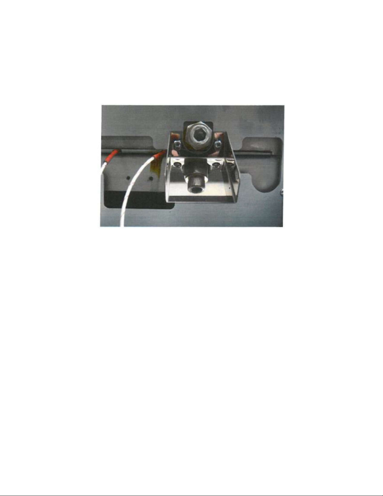
2. USE CAUTION: Drain chute, Allen screw, and glue are extremely hot! Place
a box under the drain chute and remove the Allen screw.
3. When the glue has been drained you may melt wax in the glue pot to remove
any excess glue and clean out any paper dust at the bottom. (FIG #18)
Note: There are two drain plugs on the CPB2SG model.
Figure 18
Page 17 of 26
Page 18
MAINTENANCE
DAILY MAINTENANCE
The glue level in the pot will go down as books are bound. Glue chips should
be used to replenish the pot, as needed.
o
If you see a dry spot or large air pocket on the center glue roller, add
more glue. The level of the glue should rise to about 3/4
of the glue pot.
The CPB2SG model has a level indicator in the main glue pot. The side
o
glue pot glue level should be set at around the top of the bevel gears.
Do not leave the machine powered on when not in use. This will cause the
glue to burn and darken.
o
If reheating is too time consuming, press the O button to put the
machine into Stand-By mode. This will lower the glue temperature.
Press O again to resume.
Use the supplied air gun to blow paper dust away from the glue pot.
The front and rear shafts must be cleaned regularly to allow smooth
operation of the clamp. Solvents or penetrating oils may be used to remove
bogged down or stuck during operation.
WEEKLY MAINTENANCE
Check that the Notching Pins are sharp to avoid straining of the roughing
motor and to ensure clean notching for adequate glue penetration. When
replacing dull Notching pins, follow the instructions in the Troubleshooting
Section of this manual under ROUGHING BLADE & NOTCHING PIN
ADJUSTMENT.
Air compressor: The compressor should be bled weekly to remove moisture
build up inside the tank. The bleed valve is located at the bottom of the
compressor tank.
Check the oil level in the sight glass of the compressor motor. If oil is not
visible or low, add air compressor oil tube by removing the
rubber cap (opposite side from the filter). Make sure the compressor is off
when not in use. Some compressors do not require oil.
the compressor in an enclosed area and check for air leaks periodically.
Page 18 of 26
Page 19

TROUBLESHOOTING
Some adjustments require the unit to be in the SETUP mode. This is done by
turning off the unit then, while holding down the CLAMP button, turning the power
back on.
**Note: The machine will cycle continuously if the START button is pressed. Press
and hold the X button while the clamp is traveling to the right to stop the cycling or
press the Emergency stop button.
Also, while in setup Mode, the O (Stand By) Button will turn on the roughing motor.
Pressing the X button will stop the motor. Flip the toggle switch below the Main
power switch to turn off the Roughing Motor.
CAUTION: Pressing the RIGHT arrow button will close the roughing blade guard. To
reset the machine back to normal operation, simply turn machine off on again.
UNEVEN OR INCONSISTENT SIDE GLUE
Make sure the glue pot has enough glue. While the cycling, the glue
level should be about 3/4
Check that the Air compressor is on and up to pressure. There should be between
90-110 psi.
You may also need to level your nipper table. See Leveling the Nipper Table on page
16.
The CPB2SG model has its own side glue tank. There are side glue metering plates
next to each wheel. These plates can be moved in and out to allow for more or less
glue to be applied to the book.
ADJUSTING SIDE GLUE BETWEEN HEAD AND FOOT OF
BOOK
1. Put the unit
guard bracket will open.
2. Open the clamp and place a cover sheet in it, making sure the bottom
a. Close the clamp and jog it, using the left and right arrow buttons,
Page 19 of 26
Page 20

b. Check the distance from the bottom of the cover stock to the roller,
the cover stock must be the same distance above the roller from the
leading edge to the trailing edge.
3. Locate the screw on the topside of the register table where you place the
books. Level one end of the register table by turning the screws clockwise to
lower or counterclockwise to raise it using a 5mm hex key.
4. Reset the machine back to normal operation simply by turning the machine
off then on again after completing adjustments, then test by binding a book.
the nipper table. See Leveling the Nipper Table below.
ADJUSTING SIDE GLUE ON OPERATOR
AND NON-OPERATOR SIDES OF THE BOOK
CAUTION: BURN HAZARD.
Because the rear nipper table comes in before the front table does, more glue is
channeled towards the front of the book. Adjust the Metering roller until you have
enough side glue between the cover and the 1st page of the book (operator side).
Then locate the side glue wire on top of the far-right glue roller. Press the
Emergency Stop button.
Loosen the screw. Using a pair of needle nose pliers, move the side Glue Wire
slightly closer to the book to apply more or further away for less side glue between
the cover and last page (non-operator side) of the book.
Release the Emergency stop button by giving it a gentle twist clockwise.
The CPB2SG model has a side glue pot. Both side glue wheels have a scraper which
will adjust the amount of glue left on the book block.
PAGES NOT BINDING WELL
The glue needs time to cool and harden. Let them sit 1 hour before checking the
binding strength.
If the pages still come out too easily then it may need deeper roughing and/ or
notching, more glue, more nipper pressure, a longer nipper dwell time or special
glue for your product.
Page 20 of 26
Page 21

TIP: The grain direction of the paper and cover stock should follow the length of the
book's spine. This will improve the binding strength by as much as 25%. Fold the
stock in half, length wise then width wise, and see which fold looks
cleaner/smoother. The smoother fold is the grain direction. You may also try one of
these other solutions:
1. Increase the nipper finish time. Press the SET button twice to get to the
Finish Time screen. Use the UP arrow button to increase the Finish Time.
2. Increase the nipper pressure by slightly turning the book thickness wheel
to the left. Be sure not to use too much pressure. This will squeeze out the
3. Increase the amount of glue being applied by lowering the far left glue
metering roller. The glue level in the pot will go down as books are bound.
Glue chips should be used to replenish the pot as needed. If you see a dry
spot or large air pocket on the center glue roller, add more glue. The level
of the glue should rise to about 3/4" below the top of the glue pot.
4. Pull a page out of the book and check the depth of the notches. If they are
barely visible then you need to raise the notching pins. Adjust the
roughing and notching. (See Roughing Blade and Notching Pin
Adjustment below) Heavier stock or coated materials need deeper
notching and a longer nipper finish time. *Note: Notching pins must be
sharp!
ROUGHING BLADE AND NOTCHING PINS ADJUSTMENT
(CPB2SG model has a mill blade)
1. Remove the operator side guard from the top of the roughing blade.
2. Put the unit in SETUP mode as described at the beginning of this
Troubleshooting section. Turn off the Roughing motor by flipping the
toggle switch below the main power switch.
3. Remove the front panel/guard. Be careful not to pull the wires of the
display/control panel board.
4. Open the clamp and place a cover sheet in it, making sure the bottom
doesn't curl as the clamp closes. Close the clamp then jog it over the
roughing blade using the left and right arrow buttons. Press the Emergency
Stop Button.
Page 21 of 26
Page 22
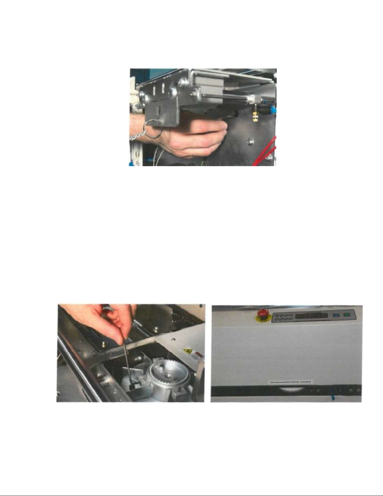
5. Loosen the setscrews locking the roughing blade assembly to the motor's
shaft (under the blade assembly) with the supplied T-handle hex key. (FIG
#19)
Figure 19
6. Adjust the roughing blade's height so that the tips of each tooth just
lightly touch the pages. Lock the setscrews once the correct height is set. The
CPB2SG model has a dial so the book block can be adjusted up or down
to remove more or less material. The notching pins still need to be
adjusted independently. Fig 20, right side picture.
7. Adjust the notching pins so that it goes no more than 1/16" into the pages.
Loosen set screws on the outside of the roughing blade assembly with a
2.Smm hex key. You may need to raise it a bit more for heavier or coated
stock. *Note: The notching pins may fall out once the setscrews are loosened.
(FIG #19)
Figure 20
8. Install the blade's guard and check that the roughing blade and notching
pins do not interfere with the guards by turning the blade by hand.
Page 22 of 26
Page 23

9. When you are done adjusting, turn the machine off then on again to return
it to normal operation. Install all guards and release the Emergency Stop
button.
UNEVEN CORNERS ON THE BOOK SPINE
valve where the machine's air hose is connected is in the fully open position. Make
sure the bleed valve at the bottom is fully closed. The pressure gauge's needle
should point approximately.75 MPa or 110 PSI (between 11and 1 o'clock). Make sure
the air hose isn't pinched or kinked.
If you have the correct air pressure and the corners still aren't even, then you may
need to level the nipper table. If one or both ends of the book have very sharp
corners, try lowering the book thickness wheel a bit.
LEVELING THE NIPPER TABLE
1. Press the 1st and 2nd buttons on the control panel (top left buttons) to raise
and close the nipper table. Remove the small front white cover stock support
tray.
2. Remove Rear Table Cover Support only if you need to adjust the rear right
side of the nipper table. You can adjust the rear setscrew on the left side
without removing this tray.
3. Loosen 2 locking screws at the corner you want to adjust with the supplied
4mm T-handle hex key.
4. Turn the adjustment setscrew with a 2.5 mm hex key clockwise to raise or
counterclockwise to lower that corner. *Note: You should adjust the front and
rear (operator and non-operator side) set screws the same amount on either
the left or right side of the nipper table. When lowering a corner, press down
slightly on that corner while tightening the two 4mm locking screws. (FIG
#19)
Page 23 of 26
Page 24
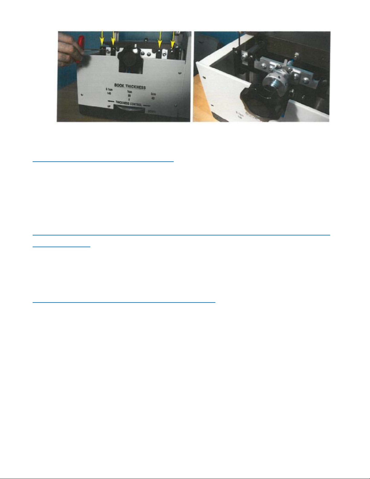
Figure 21
MACHINE DOES NOT CYCLE
Make sure the machine is up to temperature and the green lamp on the control
panel is lit. It takes approximately 45 minutes to reach operating temperature
before it will allow you to operate.
Check that the Set temp and actual temp are over 130 degrees Celsius.
MACHINE BEEPS TWICE IN RAPID SUCCESSION AND DOES
NOT CYCLE
Make sure the book is in the clamp and a cover sheet is on the nipper table and
both are jogged all the way to the right and blocking the sensors. Some dark stocks
may not activate the sensor(s).
CLAMP IS STUCK / ERROR MESSAGE
Most problems can be solved over the phone but you may need to schedule a
service call. Write down the error message and machine serial number and call
your dealer.
The front and rear shafts must be clean and slick, or the clamp will get stuck. It is
recommended that you clean the shafts daily. You may use solvents or penetrating
oil to clean any paper dust or glue residue from the shafts.
Page 24 of 26
Page 25
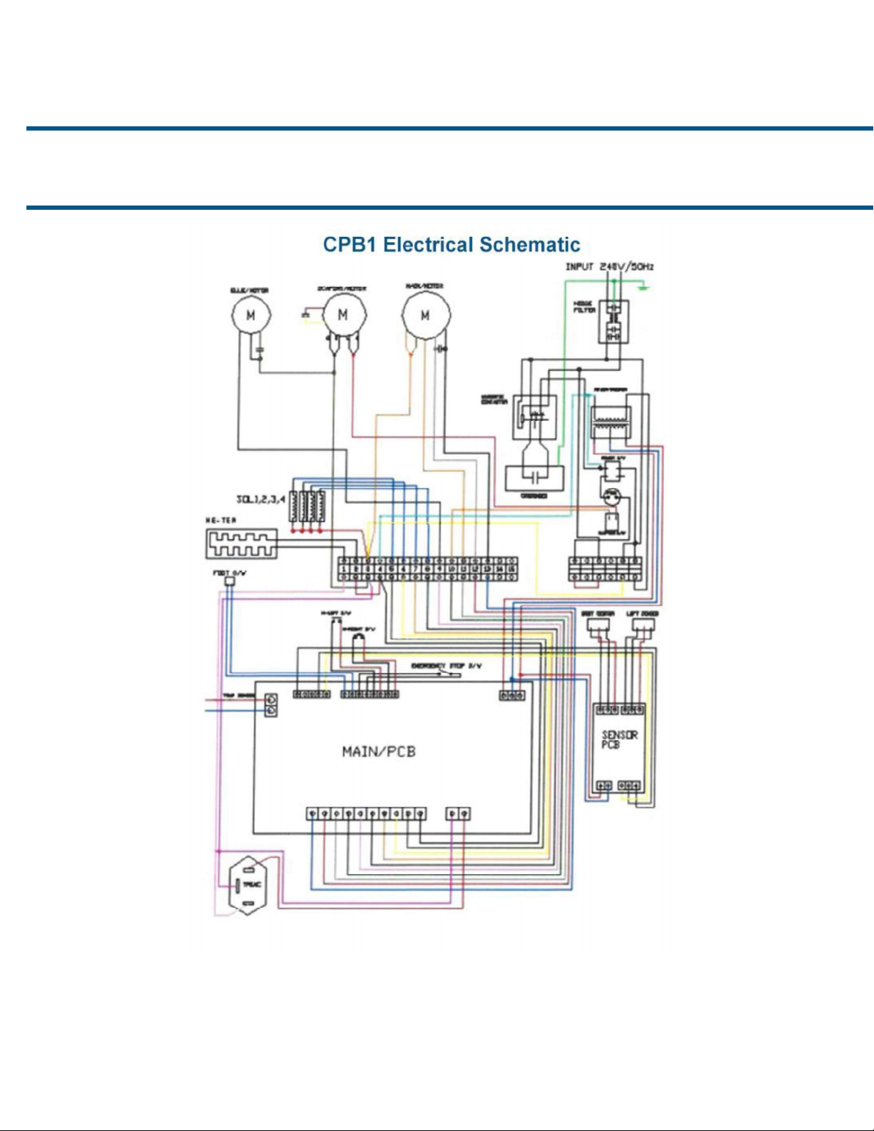
SCHEMATICS
Page 25 of 26
Page 26
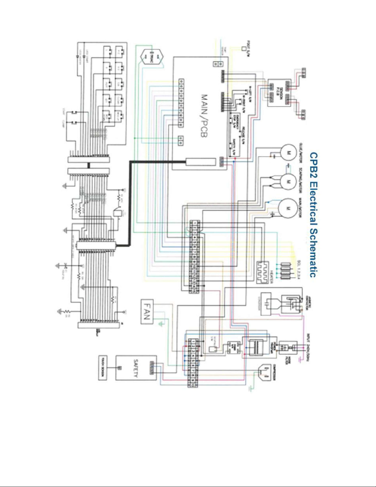
Page 26 of 26
 Loading...