

Coven 10 GMD MECC Instructions For Installation, Use And Maintenance Manual
COMBI MECHANICAL OVEN
10 GMD MECC
INSTRUCTION FOR INSTALLATION USE AND MAINTENANCE
1
CONTENTS
DIRECTIONS FOR INSTALLERS
Place of installation .............................................................................. p. 2
Installation ............................................................................................ p. 2
Positioning of the equipment ................................................................ p. 2
Type of gas .......................................................................................... p. 3
Connection to the supply system ......................................................... p. 3
Water connection ................................................................................. p. 3
Power connection ................................................................................ p. 3
First starting of the oven ...................................................................... p. 4
Controlling the functions ...................................................................... p. 4
Working of the oven ............................................................................. p. 4
Unlocking of the equipment ................................................................. p. 4
Conversion to different types of gas ................................................... p. 5
Annual maintenance ............................................................................ p. 5
Calibration, burner nozzles (Fig.2)……………...……………………….. p. 5
Gas valve (fig. 3) .................................................................................. p. 6
Exhaust of combustion……………………………………………………. P. 7
SPECIFICATIONS(table1)
Oven 10GMD MECC .......................................................................... p. 8
Installation diagram (fig.1) .................................................................... p. 9
WIRING DIAGRAM
Wiring diagram ..................................................................................... p. 10
Wiring diagram key ................................ ................................ .............. p. 11
MAINTENANCE
Replacement of gas components ........................................................ p. 12
Burner(fig.5) ......................................................................................... p. 13
Gas safety valve(fig.6) ......................................................................... p. 14
Replacement of electric components ................................................... p. 15
DIRECTIONS FOR USERS
Oven front with control panel (fig. 8) ................................ .................... p. 16
Maintenance advice ............................................................................. p. 17
Operational advice ............................................................................... p. 18
Cooking advice .................................................................................... p. 19
Directions ................................ ................................ ............................ p. 20
Control panel ...................................................................................... p. 21
Super steam cooking .......................................................................... p. 22
Mixed cooking (convection + steam) ................................................... p. 22
Dry convection cooking ....................................................................... p. 23
Fast cooling ........................................................................................ p. 23
Core probe (on request) ....................................................................... p. 24
2
WARNING
Users are recommended to check that the installation of the equipment has been
properly performed; the manufacturer cannot be held responsible for damages due to
wrong installation, incorrect maintenance, user unskilfulness.
Before starting the oven, carefully read the instructions for use. The manufacturer
cannot be held responsible for non-compliance with the regulations laid out in this
instruction manual.
All maintenance or repair interventions must be carried out exclusively by authorized
and qualified personnel. The equipment is to be controlled at least every six months, so we
recommend the drawing up of a maintenance contract.
DIRECTIONS FOR INSTALLERS
The manufacturer states that the equipments are in line with the requirements of the
following CEE directives: 90/396 CEE (gas equipments); 73/23 CEE (low tension electrical
equipments); 89/336 CEE (electromagnetic compatibility); 89/392 CEE (machinery).
The register tag is on the right side of the equipment and reports all necessary data for
installation: class, power, consumption, type of gas and so on.
PLACE OF INSTALLATION
The equipment must be installed into a well ventilated room, for either gas combustion and
change of air, as provided for by the regulations UNI-CIG 8723, act 46 (5/3/90).
INSTALLATION
Installation of the equipment, adjustments of safety valve and repair interventions can be
carried out exclusively by a qualified installer, by means of suited tools and in compliance
with rules and requirements for the safety in fuel gas use, act 1083/6.12.71; safety
regulations for gas cookers; prevention of accidents regulations; moreover, regulations in
force by fire department are to be observed.
POSITIONING OF THE EQUIPMENT
Position the equipment on a horizontal, level, plane. The distance of the oven’s sides from
the wall of the room must be at least 50 cm.

3
DIRECTIONS FOR INSTALLERS
TYPE OF GAS
The type of gas the equipment has been originally pre-arranged and tested for is marked on the
tag stuck on the right side of the equipment. If such type of gas is not available, you have to adapt
the equipment according to the instructions “Conversion to different types of gas”.
CONNECTION TO THE SUPPLY SYSTEM
Connection to the fitting ¾” G ISO R7 of the equipment can be either fixed or in a way such that it
can be disconnected by means of a type-approved supply cut tap.
Pipe section must be in proportion to its length and to the gas flow of the equipments it has to
supply. In any case, it must be inserted according to the regulations UNI-CIG 8723. As to liquefied
gas, you have to insert on the supply pipe a pressure regulator proportionate to gas flow.
If you use flexible pipes, these ones must be made of stainless steel and type-approved. When the
connection is done, you have to test the tightness of the pipes by means of a gas leak detector.
WATER CONNECTION (Fig. 1)
Connect the oven to water grid at point C, and when the connection is done check that there are
no leaks. Use only materials (pipes, fittings etc.) in keeping with the regulations in force and that in
any case don’t leave rust build-up.
Warning: upstream of the equipment the installation of an effective decalcifying device is of the
utmost importance; water hardness has to be lower than 3°F. The non-installation of such device
causes in a short time the formation of limescale and an abnormal working of the equipment.
POWER CONNECTION
The equipment is pre-arranged to work at the voltage shown on the features tag. To reach the
connection terminal board (A fig. 1), remove the right side of the equipment by unscrewing the
fixing screws.
The features of flexible cable for connection to power line must not be lower than those of the kind
with rubber insulation model H07RN – F and the cable section has to be equivalent to the one
shown in TABLE 1. Connection to power line must be made by inserting an automatic switch with a
sufficient current-carrying capacity (see TABLE 1) and in which the span between contacts is at
least 3 mm. In order to correctly run the oven, it’s very important to observe the polarity of
supply cables; a wrong positioning of supply cables may cause the valve to fail (F =
BROWN – N = BLUE).
Moreover, during the working of the equipment the supply voltage must not differ from the value of
voltage rating ±10%.
The oven must be connected to a ground outlet. Inside the oven, in the connection terminal board,
there is a terminal with the symbol : connect the ground cable here.
The equipment must be inserted in an equipotential system, whose effectiveness must be checked
according to the regulations in force.
Connection must be made using a screw with the symbol (EQUIPOTENTIAL); such screw is
positioned in the rear of the equipment.
The manufacturer cannot be held responsible if this accident-prevention regulation is not
observed.
4
DIRECTIONS FOR INSTALLERS
FIRST STARTING OF THE OVEN (Fig. 9)
Turn on the gas
Turn timer 1 to the right.
Turn cooking-program selector 3 to the left, on the position "convection".
Set a cooking temperature by means of thermostat 4.
Check the ignition and the blowing out of the burner’s flame when the set temperature is
reached with the thermometer 5, by means of the attendant warning light.
A flashing sound signal indicates that the set time is over.
N.B. If at the first attempt the burner does not start, check that:
gas is on
ignition indicator is on
ignition and flame detection electrodes are in the right position.
At the first ignition the gas valve may have an arrest (warning light of button RESET). Wait
10 seconds, then push the button RESET.
CONTROLLING THE FUNCTIONS
Start the oven as explained in the section “First starting of the oven”. Control ignition and
blowing out of the flame when the desired temperature is reached.
WORKING OF THE OVEN
At starting the equipment runs a self-assessment of its own effectiveness. During waiting
time (or pre-ventilation time) (TW = 1.5 sec.), the internal logic checks the booster of the
flame signal. A parasitic flame signal or a booster failure corresponding to conditions of
flame “present” prevent the starting of the equipment.
At the end of waiting or pre-ventilation time, gas solenoid valve is powered and the ignition
device is started, thus beginning safety time (TS = 10 sec.).
The ignition device is disconnected if the equipment, during safety time, detects the
presence of flame.
If the equipment, during safety time, detects no flame signal, when safety time is up there i
san arrest, and therefore the gas solenoid valve is closed, the ignition device is
disconnected and the arrest signalling (RESET) is put into operation.
If during safety time there is a flame extinguishing, the ignition device is reactivated within
1 second.
UNLOCKING OF THE EQUIPMENT
When the equipment makes an arrest, you need to wait at least 10 seconds before
unlocking it pushing the button RESET (6); if you don’t observe such waiting time, the
system doesn’t start again.
5
DIRECTIONS FOR INSTALLERS
CONVERSION TO DIFFERENT TYPES OF GAS
If the equipment has to work with a gas different from the preset one (see the register tag on the right side of
the equipment), you need to convert it by carefully paying attention to the following instructions:
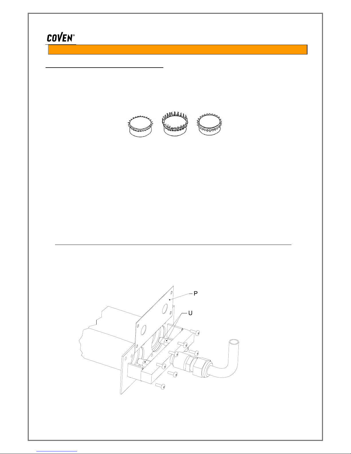
a) REPLACE BURNER NOZZLES (Fig. 2)
The nozzles are in the lower part – back right. Access the nozzles from under the frame.
Replace the nozzles U on the collector.
b) FEATURES OF THE BURNER’S FLAME
After adjusting the burner’s air, the flame should have the following characteristics:
Fig. A Fig. B Fig. C
Too much air on flame (Fig. A). Light blue flare. The flame tends to move away (blow) or return (return of
flame) with possibility of lighting up at nozzle.
Too little air on flame (Fig. B). Flare with yellow tips. Formation of harmful carbon monoxide, which causes
black smoke that sticks to the combustion chamber. The burner’s yield is very negative.
Regular flame (Fig. C). Dark blue flare, maximum yield of burner.
ATTENTION: BAD COMBUSTION
Bad combustion may be dangerous for the people around the oven.
CASES OF BAD COMBUSTION
- bad draft (difficult release of exhaust fumes)
- nozzles with wrong holes (bigger) for the gas used (see TABLE 1)
- volume of air under the oven insufficient (see point 3).
1. ANNUAL MAINTENANCE
Verify that the stainless steel structure between the burner and the combustion chamber is integral.
Verify the conditions of the various gaskets (door, lamp holder, etc.)
CALIBRATIONS AND ADJUSTMENTS (Fig.3)
Verify at inlet 8, that the inlet pressure is correct:
gas G20 = 20mbar, gas G30 = 30 mbar
After completing the control tightly fasten the screw 10.
Fig. 2
6
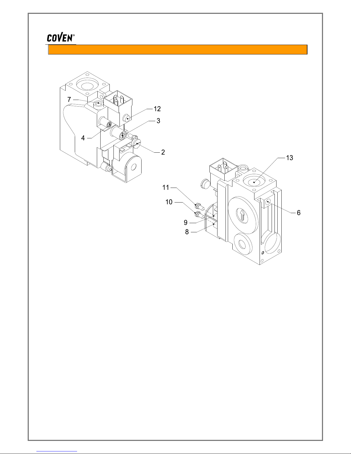
GAS VALVE
Fig. 3
KEY
2. Pressure control screw cap
3. Control screw of pressure to main burner
4. Control screw of gas flow to pilot burner
5. Thermo-couple joint
6. Thermo-couple alternative joint
7. Pilot outlet
8. Gas pressure outlet entering duct
9. Gas pressure outlet coming out from burner
10. Inlet pressure outlet cap screw
11. Outlet pressure outlet cap screw
12. Driving solenoid
13. Main gas outlet to burner
7
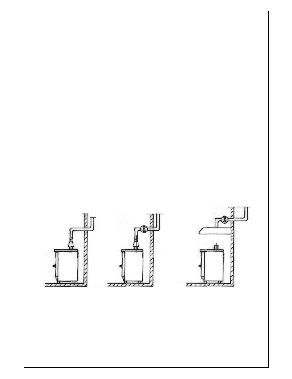
EXHAUST OF COMBUSTION SUBSTANCES
The equipment is fitted with a steam exhaust to release the combustion products that must
be connected in one of the following ways, as laid out by the regulations in force.
EQUIPMENT TYPE B11 (SEE FEATURE LABEL)
1) Natural exhaust. Connection to a natural draught exhaust, perfectly efficient thanks to
an anti-wind connection. The combustion products are directly released outside (see
Fig. C)
2) Direct forced exhaust. Connection to a forced draught exhaust, through anti-wind
connection (see Fig. B). The delivery of gas to the equipment must be directly
connected to the forced exhaust system and must be interrupted if the gas flow falls
below the values indicated in 4.3 of the UNI-CIG 8723 standard. Only manual
redelivery of gas to the oven must be possible.
3) Forced exhaust under hood. In the case of under hood installation, the terminal part of
the oven’s exhaust duct must be at least 1.8 m. from the surface where the equipment
is installed on (floor), the outlet section of the combustion product exhaust ducts must
be installed within the external area of the base of the hood itself (Fig. A). The gas
delivery system to the equipment must be directly connected to the forced exhaust
system and must be interrupted if the gas flow falls below the values indicated in the
installation rules. Only manual redelivery of gas to the oven must be possible.
Fig. A Fig. B Fig. C
 Loading...