

Page 1

For research use only
E220
evolution
USER MANUAL
Instrument and software developed for
high performance sample preparation
using adaptive focused acoustic energy
Product Name: E/LE220-Series
Model Numbers: E220 evolution
Software: SonoLab 7
E220 evolution User Manual Page 1
Page 2
UNIVERSAL PRECAUTIONS
Universal Precautions should be followed on all specimen samples, regardless of whether a sample is known to contain
an infectious agent. Laboratories handling specimen samples are advised to comply with applicable parts of the following
governmental and clinical standards, or their equivalent in the country of use:
• Centers for Disease Control (CDC), Universal Precautions for Prevention of Transmission of HIV and Other
Trademarks
Patented or patent pending and registered or registration-pending trademarks of Covaris are protected.
Registered names and trademarks used in this document, even when not specifically marked as such, are not to be
considered unprotected by law.
WCS and AFA are either registered trademarks or trademarks of Covaris, Inc. in the United States and/or other
countries.
Clorox is a registered trademark of The Clorox Company.
Teflon is a registered trademark of The DuPont Company.
Information subject to change w ithout notice
For Research Use Only
Not for use in diagnostic procedures
Publication P/N 010264
Revision E, July 2017
Product covered by Patent No. US6, 719,449, US6, 948,843, and ot her pend ing app lic ati ons
Copyright © 2017 Covaris, all rights reserved.
Covaris, Inc.
14 Gill St, Unit H
Woburn, Massachusetts
01801-1721 USA Printed in U.S.A.
Bloodborne Infections, published 1987, updated 1996
• Clinical and Laboratory Standards Institute (CLSI), GP17-A2 Clinical Laboratory Safety; Approved Guideline -
Second Edition, published 2004, ISBN 1 -56238-530-5
• Clinical and Laboratory Standards Institute (CLSI), M29-A3 Protection of Laboratory Workers from
Occupationally Acquired Infections; Approved Guideline, Third Edition, published 2005, ISBN 1-56238-5674
• Occupational Safety and Health Administration (OSHA), 29 CFR 1910.1030 Bloodborne Pathogens
• International Standards Organization (ISO) 15190:2003, Medical Laboratories – Requirements for Safety
E220 evolution User Manual Page 2
Page 3

Warnings
For safety of operating personnel:
Make sure that the equipment is properly grounded. DO NOT operate if it is not properly grounded.
The unit is equipped with a power plug appropriate for the destination country. DO NOT, under any circumstances,
remove the grounding prong from the power cord.
Do not run an acoustic treatment with the Acoustic Assembly and sample cover in the UP position or without a water
bath - the acoustic system will not work.
If there is any indication that the Safety System is not functioning properly, DO NOT operate the equipment and
contact Covaris immediately.
If the equipment is used in a manner not specified by the manufacturer, the protection provided by the equipment
may be impaired.
To prevent damage to the equipment:
The instruments are designed to operate in ambient laboratory conditions e.g., 19ºC to 25ºC (66ºF to 77ºF). DO
NOT operate the instrument in a cold room environment; the system is designed to operate with a water bath and
re-circulating heater/chiller apparatus to control sample temperature.
NEVER run a method without a water bath; this could damage the transducer. The instrument is equipped with a
water level sensor to protect the transducer and degassing pump. The system will not allow the degassing pump to
operate or the acoustic treatment to start unless an adequate volume of water is detected.
Distilled or deionized water should be used to fill the water bath.
Unless a Water Conditioning System (WCS) is employed, empty the water bath and wipe it dry EVERY day with a
lint-free cloth. DO NOT leave water in the tank for an extended time as there is no water filtration or water cleaning
system within the apparatus (unless WCS is employed).
Do not employ isopropyl alcohol, ammonia-based or abrasive cleaners on the water tank, as these will damage the
acrylic surfaces.
Establish a standard of operation and periodically test equipment, as described in Maintenance (see section 6.0) of
this manual.
Loading third party software onto the computer may interfere with system operation. Please consult with Covaris.
E220 evolution User Manual Page 3
Page 4

Warranty
When used in accordance with written instruction and under normal operating conditions, the Covaris
instruments are guaranteed to be free of defects in MATERIAL and WORKMANSHIP for one (1) year from the
date of original delivery by an authorized representative. Any component which proves defective during the
stated period will be repaired free of charge or replaced at the sole discretion of Covaris, F.O.B., Woburn,
Massachusetts, U.S.A. provided the defective component is returned properly packaged with all transportation
charges prepaid. The customer is expected to perform basic diagnostics and component replacement with
telephone support from Covaris personnel. If Covaris personnel are required to perform on-site repair, all travel
related costs are paid by the customer. A limited warranty as specified may apply to certain components of the
equipment.
Warranty Exceptions
This warranty is void if failure of the software or hardware has resulted from accidents, abuse, improper
maintenance, or repair, or misapplication by the customer. It is also void if damage is caused by any
unauthorized attachments or if modifications are made to the equipment. Removing or tampering with the
Safety Enclosure will void the warranty, and the customer will assume all liabilities.
This warranty is limited to the original purchaser and is not transferable.
The software will perform according to the accompanying written materials and the medium on which the
software is delivered is free of defects in materials under normal use and service. The warranty is void if
damage has resulted from third party software not intended for use with the system.
The high power focused transducer is designed to give maximal mechanical energy output in water. Permanent
damage to the transducer and electronic circuits could result if the transducer is operated without water.
Operation of the system without water in the water bath voids the warranty.
CONTACT COVARIS, INC. SHOULD YOU HAVE ANY QUESTIONS CONCERNING EQUIPMENT
Warranty Services
The purchased equipment is covered by a twelve (12) month warranty which includes all the service and
support necessary so that the customer can operate the equipment successfully. Extended warranties are
available at the end of the original 12 month warranty period.
Services included with the original purchase of the system are:
Technical Support – On-going assistance with the operation or application of the equipment and/or
troubleshooting is provided via :
• Telephone (+1 781 932 3959) during the hours of 9:00am to 5:00pm, Monday through Friday,
o United States, Eastern Standard Time (EST)
o Greenwich Mean Time (GMT-05:00)
• E-mail queries to [email protected]
Parts Replacement – Replacement of parts (excluding consumables) from normal operation of equipment are
provided on a priority basis. All labor and shipping charges are included. Failure due to accident, abuse, or
improper operation is not covered.
An Operator’s Manual is provided with the equipment. This manual includes sections on the operating
instructions, maintenance guid elin es, and troubleshooting tips.
E220 evolution User Manual Page 4
Page 5

TABLE OF CONTENTS
1.0
INTRODUCTION ................................................................................................................................ 6
1.1 Overview of the User Manual ......................................................................................................... 6
1.2 The E220 evolution and the Covaris Process ................................................................................ 6
INSTALLATION AND SETUP ............................................................................................................ 7
2.0
2.1 Assembly ........................................................................................................................................ 7
2.2 Installation ...................................................................................................................................... 8
3.0 GETTING STARTED ....................................................................................................................... 11
3.1 Fill the Water Bath ........................................................................................................................ 11
3.2 Start the System ........................................................................................................................... 11
3.3 The SonoLab Run Screen - Running a Method ........................................................................... 13
3.4 System Shutdown ........................................................................................................................ 17
3.5 Temperature Control .................................................................................................................... 18
3.6 Degas System .............................................................................................................................. 19
4.0 SonoLab™ APPLICATION SOFTWARE ......................................................................................... 19
4.1 Create and Edit Methods ............................................................................................................. 20
4.2 Temperature Tab.......................................................................................................................... 25
4.3 Saving Methods in Folders ........................................................................................................... 26
4.4 History Tab ................................................................................................................................... 27
4.5 Setup Screen ................................................................................................................................ 27
4.6 Maintenance Screen .................................................................................................................... 32
4.7 About Tab ..................................................................................................................................... 33
Motion Tab ................................................................................................................................... 33
4.8
5.0 SYSTEM SPECIFICATIONS ........................................................................................................... 35
6.0 MAINTENANCE ............................................................................................................................... 36
6.1 Cooling Air Intake ......................................................................................................................... 36
6.2 Water Bath ................................................................................................................................... 36
6.3 Transducer ................................................................................................................................... 36
6.4 Safety System .............................................................................................................................. 36
6.5 Degassing System ....................................................................................................................... 36
6.6 Cleaning the System .................................................................................................................... 37
7.0 TROUBLESHOOTING ..................................................................................................................... 38
Appendix A: Sugges ted E220 evolution IQ / OQ / PQ ................................................................................ 40
Appendix B: E Series Site or Transport Preparation ................................................................................... 46
Appendix C: Installing SonoLab Software, Firmware and Instrument Drivers ............................................ 48
Appendix D: Recirculating Chiller ................................................................................................................ 53
Appendix E: Humidity and Water Management in Covaris E and LE Systems ……………………………..55
E220 evolution User Manual Page 5
Page 6

NOTE: Inconvenience if disregarded.
CAUTION: Equipment damage may occur.
WARNING: Personal injury may occur.
1.0 INTRODUCTION
1.1 Overview of the User Manual
This manual contains operation and maintenance instructions for the Covaris E220 evolution
Focused-ultrasonicator. This document contains information essential to the proper use and care of
the equipment.
Should any unforeseen problems occur with the normal operation of the equipment, contact Covaris
Technical Support immediately.
The following definitions apply in this manual:
There is also a PDF version of this manual, typically available on the computer desktop. Open the
manual by double clicking the user manual icon.
1.2 The E220 evolution and the Covaris Process
The E220 evolution Focused-ultrasonicators are based on Covaris Adaptive Focused Acoustics
(AFA) technology. This instrument is designed to provide researchers an integrated stand-alone tool
to be used in a laboratory environment. The instrument is ideal for those who work with cell lysing,
DNA shearing, or chromatin shearing.
The system is comprised of the Treatment System which delivers the acoustic energy to the sample,
the Safety System which protects users from inadvertently contacting the high intensity acoustic
energy, and the Computer and Application Software which provides users an interface to control the
device.
The Covaris Process uses adaptive focused acoustic energy to precisely control cavitation and
acoustic streaming within the sample treatment vessel in a non-contact, isothermal fashion. Focused
acoustic energy is generated and delivered to individual samples. The mechanical energy imparted
on the sample results in a controlled series of compression and rarefaction events.
E220 evolution User Manual Page 6
Page 7
2.0 INSTALLATION AND SETUP
2.1 Assembly
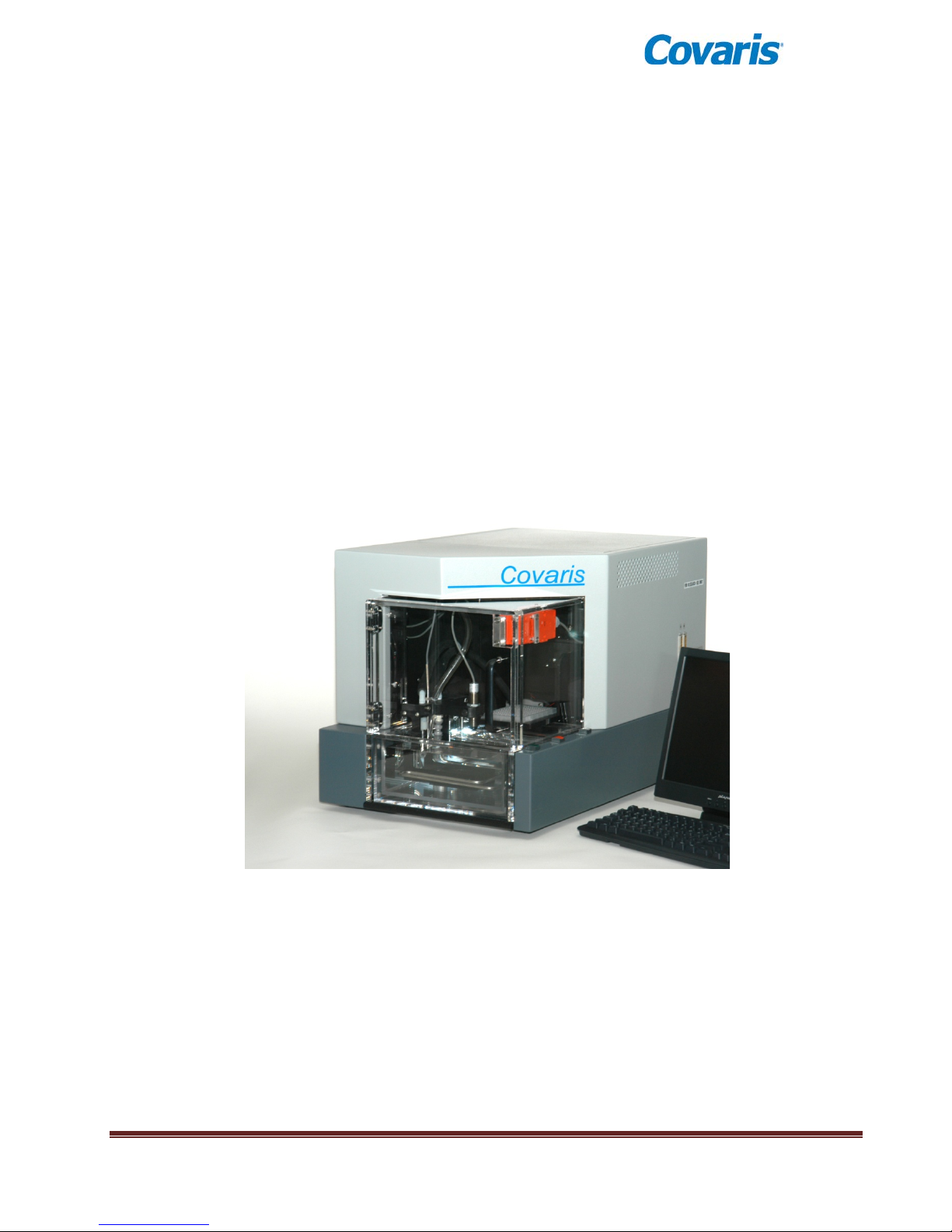
The following items should be found in the crate containing the instrument:
• Main Unit
• Quick Start User Guide
• User Manual
• Notebook Computer with AC Adapter
• Cables
o USB cable
o Instrument power cord
o Computer AC Adaptor power cord
• Accessories
o Chiller Hose Kit
o Sample Tubes & Racks (varies by application)
o Water Tank (installed in main unit)
E220 evolution User Manual Page 7
E/LE Series Focused-ultrasonicator
Page 8
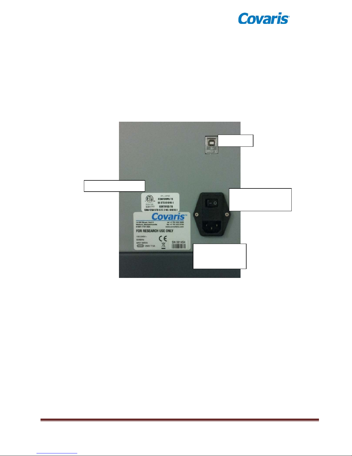
USB Port
Product Safety Label
Serial Tag,
Line Power Label
AC Line (Mains) Input
2.2 Installation
2.2.1 Unpack the instrument and place it on a table or bench, with space to accommodate the
instrument and the laptop. The recirculating chiller may be placed on the floor to save
bench space.
2.2.2 Please refer to the rear of the instrument’s right side panel and identify the following
features:
and Power Switch
Regulatory and
The Rear Right Panel of the System
E220 evolution User Manual Page 8
Page 9
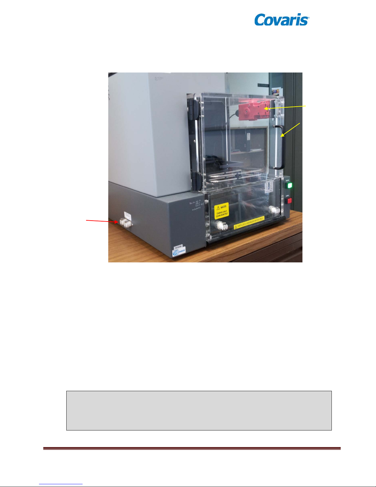
Quick-connect Ports for
Door Lock Release
Stop Button
Enclosure Door
2.2.3 Refer to the figure below and identify the following items:
Button
Safety Lock
Enclosure Door
Handle
Chiller Hoses
2.2.4 Plug the instrument into a power source using the enc l osed line cord. The instrument is
a “universal input” device and automatically employs any worldwide line voltage or
frequency (100 to 240 volts AC, 50 or 60 Hz). Leave the instrument power and
notebook power switched OFF at this time.
2.2.5 Plug one end of the USB cable into the USB Port, and the other end into any USB port
on the notebook computer.
2.2.6 Connect the computer to a power source. Connect the mouse or other accessories to
the computer.
2.2.7 Connect the two hoses provided for coolant flow from the chiller. The connections are
bi-directional. (There is no defined IN or OUT.)
2.2.8 Connect the hoses to the chiller. Please refer to Appendix D and your chiller operation
manual for details on chiller connection and operation.
2.2.9 Position the instrument and computer in your work space as desired.
CAUTION: When positioning the system, please keep the fan and rear panel vents
free of obstructions that may block the flow of air.
CAUTION: To prevent chiller damage, use of a 20% glycol solution in the circulating
chiller is required. Please refer to the chiller’s user manual.
E220 evolution User Manual Page 9
Page 10
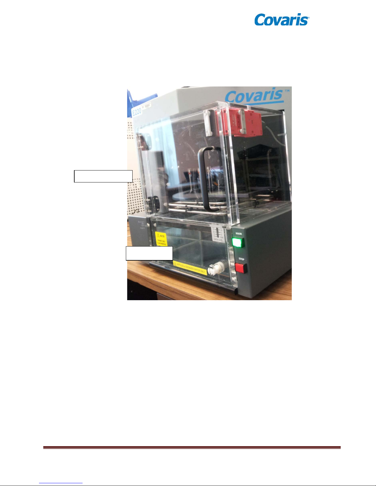
Safety Enclosure
Water Tank
2.2.10 Power on the instrument using the power switch at the right rear, at the pow er entr y
module.
2.2.11 Press and hold the green ‘Door’ button while pulling the door handle to open the safety
enclosure front door. Slide out the water tank and remove it from its plastic shipping
bag. Remove and discard the desiccant pack.
Safety Enclosure and Water Tank
2.2.12 If a Water Conditioning System (WCS) will be employed with the instrument, please
refer to the WCS User Manual for further instructions. The WCS removes biological
growth and particulates from the water, allowing bath water to remain in place for up to
one month.
2.2.13 The instrument is now ready to be started.
E220 evolution User Manual Page 10
Page 11
3.0 GETTING STARTED
3.1 Fill the Water Bath
The instrument’s transducer must be immersed in a water bath to transmit highfrequency, focused acoustic energy to the sample tube. For best performance,
employ only clean, distilled or deioni zed water in the b ath.
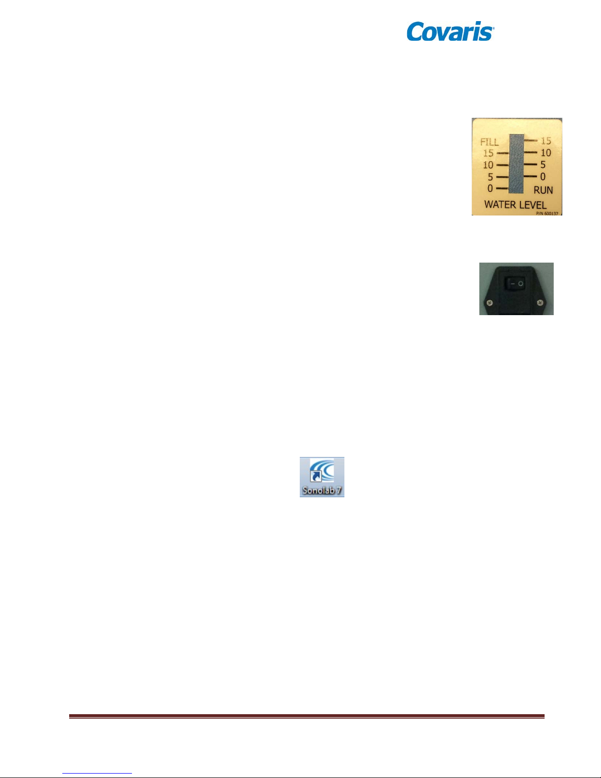
Open the front door, remove the tank and fill to the level specified in the protocol
to be used. Typical DNA Shearing protocols call for water level 6. Avoid filling
higher than 15, as the tank may overflow. Employ the markings on the FILL side
of the gauge. The tank holds approximately 01.25 gallons (5.0 liters).
Once the tank is in place and the Acoustic Assembly is lowered into the bath, the
water level should be read from the RUN side of the label.
3.2 Start the System
Turn the instrument po w er O N using the power switch located on the rear, right side
of the instrument at the power entry module. When power is ON, the green doorlock release switch will illuminate and the ventilation fans in the rear panels will run.
Also start the external chiller, programming its set point to a few degrees below the
desired instrument bath temperature. Be sure to employ a 20% glycol solution
inside the chiller to prevent freezing. Do not use undiluted glycol solution.
®
Start the system computer. The computer employs a Windows
Operating System (XP, 7 or 8).
SonoLab 7 is an application used to control a Covaris Focused-ultrasonicator for processing a
biological or chemical sample. It is designed to create, edit, and run a processing program called a
method. It has provisions to run, pause or stop a method and view execution histories whic h contai n
a record of key instrument parameter values during a run. It also contains editors for customizing
system settings and performing maintenance functions.
SonoLab 7 is installed on the computer purchased with the instrument. No further installation
or configuration is required.
Find the SonoLab 7 icon on the desktop:
If the icon is not visible, or if SonoLab 7 is not installed, please refer to Appendix C or contact
Covaris for installation instructions.
By default, there is no login required for SonoLab. To secure SonoLab by requiring users to login
and limiting user permissions, see ‘User Authentication’ in section 4 of this manual.
E220 evolution User Manual Page 11
Page 12
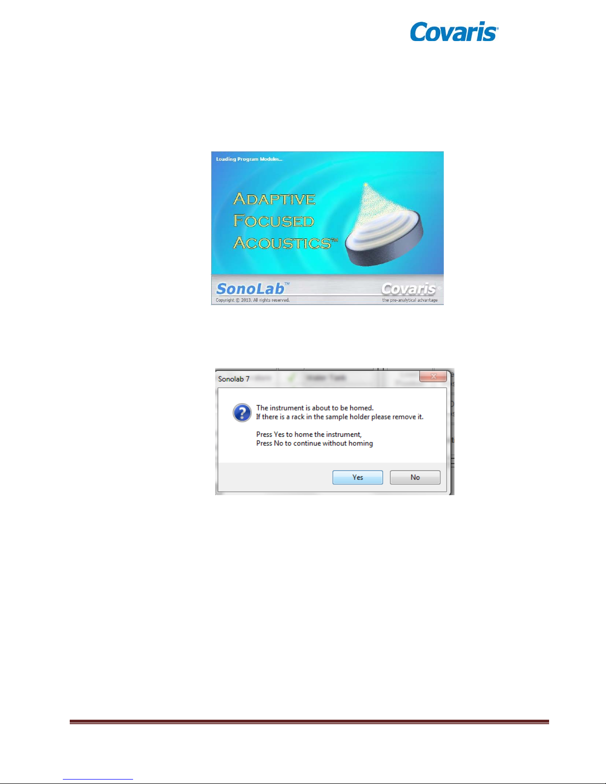
Double-click on the SonoLab icon to start SonoLab. An animated splash screen will appear:
Following the splash screen, the SonoLab Run Screen will appear with the motion system homing dialog box
in front of it:
Click ‘Yes’. The transducer and sample holder mechanical assemblies will move into position and
the SonoLab ‘Run’ screen will display.
E220 evolution User Manual Page 12
Page 13
If the instrument is powered ON and connected to the laptop via the USB cable, SonoLab will
connect to the instrument, display “E220 evolution” at the top center of the screen.
If SonoLab does not connect to the instrument, the Run Screen will not appear. SonoLab will display
the About Screen and the status “Disconnected” will be displayed in place of the instrument model.
In this case, please refer to Section 7.0 for diagnostic instructions.
3.3 The SonoLab Run Screen - Running a Method
3.3.1 Instrument Status & Basic Controls
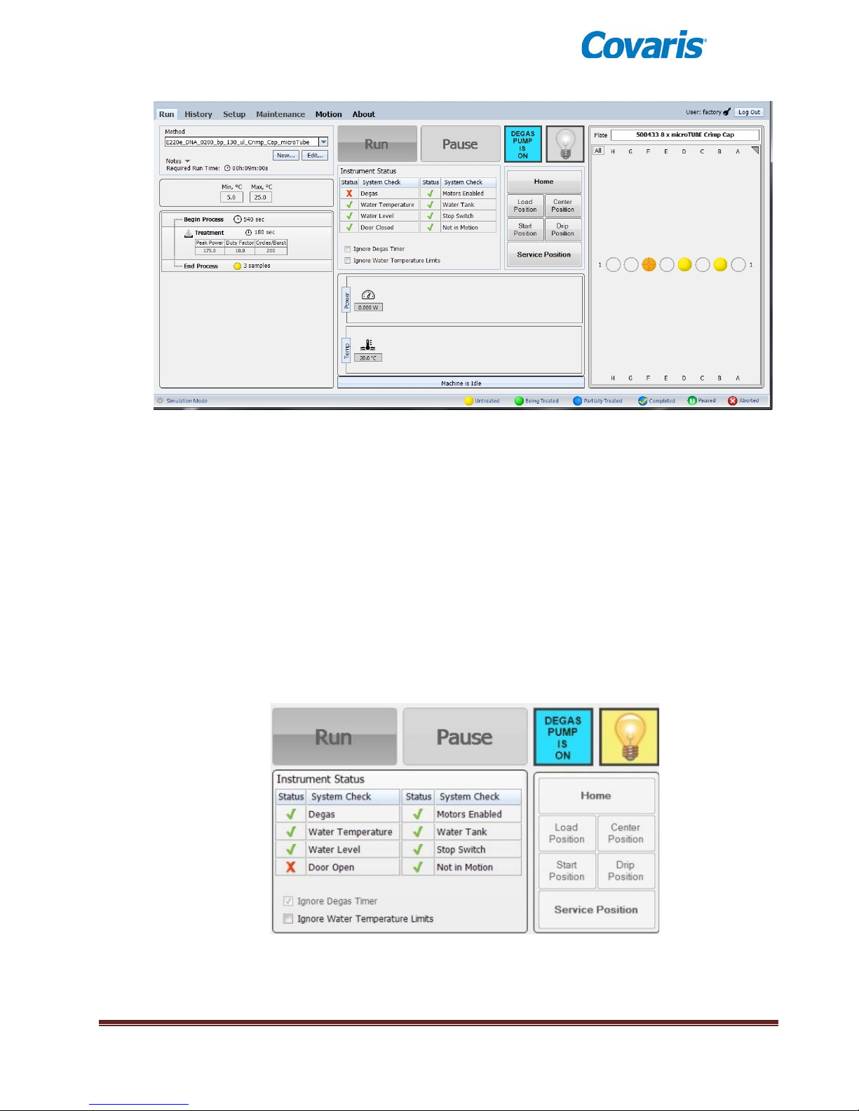
System attributes are displayed on the Run Screen as green (acceptable) or red. The SonoLab
Run button will remain gray and inactive unless a method has been selected, the degas pump is
ON, and all Status conditions are green (acceptable) or overridden. Any method will be paused
if any status changes to not acceptable while the method is running.
The status indicators and controls are described below:
E220 evolution User Manual Page 13
Page 14

Status Indicators
• Degas Pump is both a control and indicator for the instrument degas pump. The pump is
automatically turned ON when SonoLab starts. When ON, the degas pump removes
dissolved gas from the bath water. Clicking on the switch image will turn the pump OFF.
Clicking again will turn it ON.
Lightbulb is also both a control and indicator. The enclosure light is automatically turned on
•
when SonoLab starts. Clicking on the light bulb image will turn the light OFF (eg. for treating
light sensitive samples); clicking again will turn it ON.
•
Degas: To ensure properly degassed water, the degas pump should operate continuously
for at least 60 minutes. The Degas indication will turn green once this criterion has been
met. If the degas pump is turned OFF, this timer resets. Operators may click “Ignore Degas
Timer” to bypass this status check.
Water Temperature indicates if the bath temperature is between the minimum and
•
maximum set for the selected method. Operators may click “Override” to bypass this status
check. See the Temperature Control later in Sec t ion 3 and Appendix D for details on using
the external chiller to maintain bath temperature within desired limits.
Water Level indicates if there is enough water in the water tank for safe operation of the
•
instrument. Water levels near or below “0” on the WATER LEVEL label will cause this
indicator to turn red.
Door Open: A green check indicates that the door is properly closed.
•
Motors Enabled indicates that motion system for positioning the samples is ready.
•
•
Water Tank: A green check indicates that the water tank is present and properly positioned
in the instrument.
Stop Switch: A green check indicates that the red ‘Stop’ switch on the front of the
•
instrument is not pressed.
Not in Motion indicates that the motion system is idle.
•
Controls
• Run button starts a treatment method. It will be disabled (grayed out) unless all of the
above status indicators contain the green check mark, or are overridden.
• Pause button interrupts the treatment. Details of the ‘Run’ and ‘Pause’ button operation are
described in the section, ‘Running a Method’ below.
The following buttons cause the instrument motion system to move the sample tray to
predefined positions.
• Home moves all motion axes to their initialized position, as occurs when the software starts.
• Load Position moves the tray to the front of the safety enclosure to facilitate loading
samples.
• Start Position takes the sample tray to the treatment position of the first tube of the
currently selected method. This position may be used to verify that the water level in the
bath is correct.
• Drip Position raises the sample tray above the bath water to allow excess water to drip
from the sample, if desired, prior to removing the sample from the instrument.
E220 evolution User Manual Page 14
Page 15
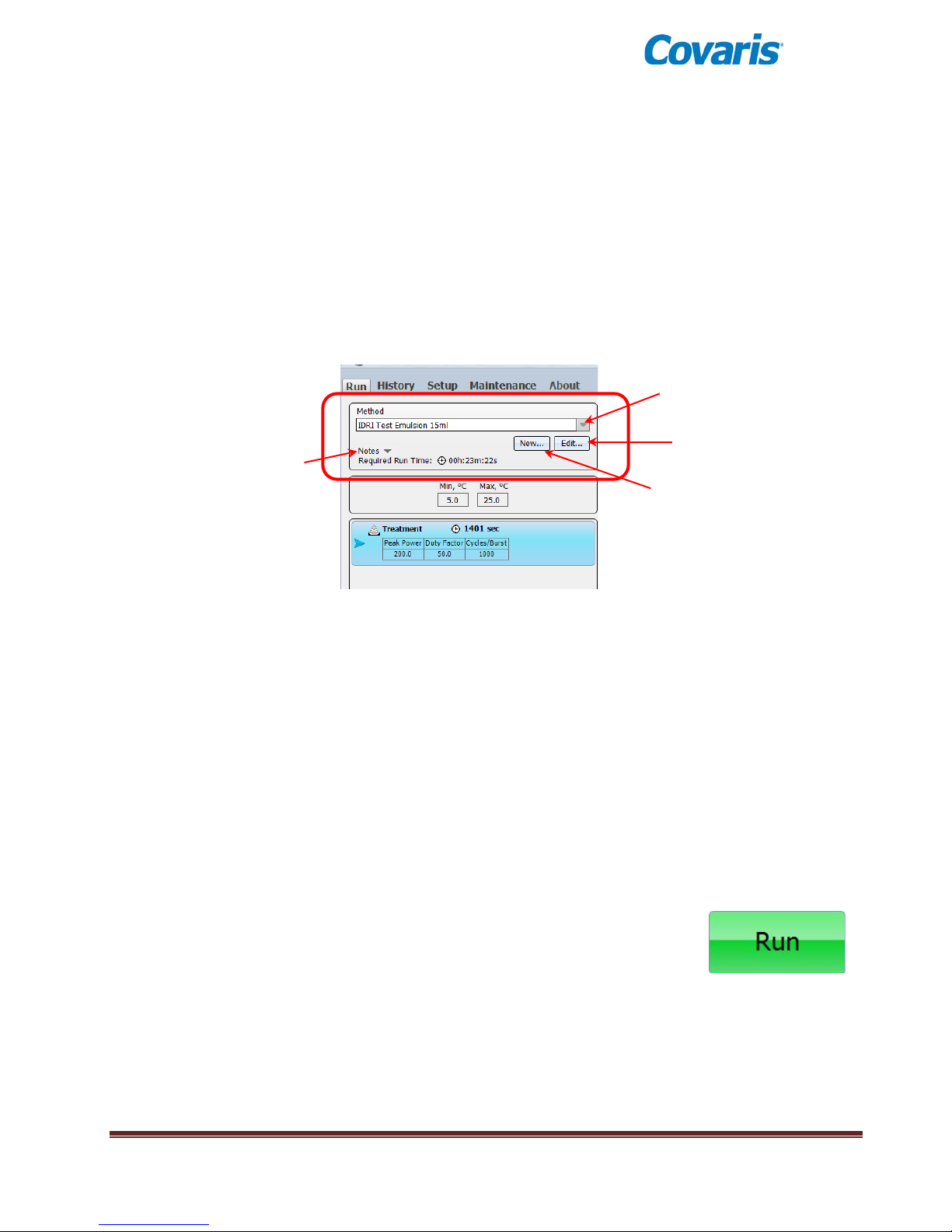
Pull down menu
Edit the selected
method
Create a new method
Run/Creation Notes
(Click to expand)
• Service Position raises the sample tray and the transducer assembly allowing the water
bath to be removed from the instrument.
• Center Position moves the sample tray to the center of its travel. This position is primarily
used by service personnel.
3.3.2 Select a Method
To select and load an acoustic Method, click the pull-down menu of the “Method” combo box, as
shown below, and a list of existing method names along with their detailed information will
appear. Navigate through the list with the vertical scroll bar and click to select a Method.
If no methods appear in the pull-down menu, then a new method must be created. Please see
Section 4 for instructions on creating and editing methods.
3.3.3 Run a Method
To start an acoustic treatment, the following conditions must be met:
• There must be an acoustic method selected in the Method box
• The Degas pump must be running
• The Degas pump timer must see the pump running for 60 minutes (or override)
• Water Temperature must be within acceptable Min and Max limits (or override)
• The Water Tank must be present
• Water Level must be at or above that required for correct operation
• The front door must be closed
The Run button will remain gray and inactive until all of these conditions
are met. Once a method has been selected and all system attributes
are acceptable or overridden, the Run button will become active
(green).
Click Run to start the selected method. The sample tray will move the first sample above the
transducer and acoustic power will be applied according to the acoustic parameters specified by
the method. At the same time, the ‘Run’ button becomes a grayed out ‘Abort’ button and the
‘Pause’ button is enabled. See details on paus ing the method below.
E220 evolution User Manual Page 15
Page 16
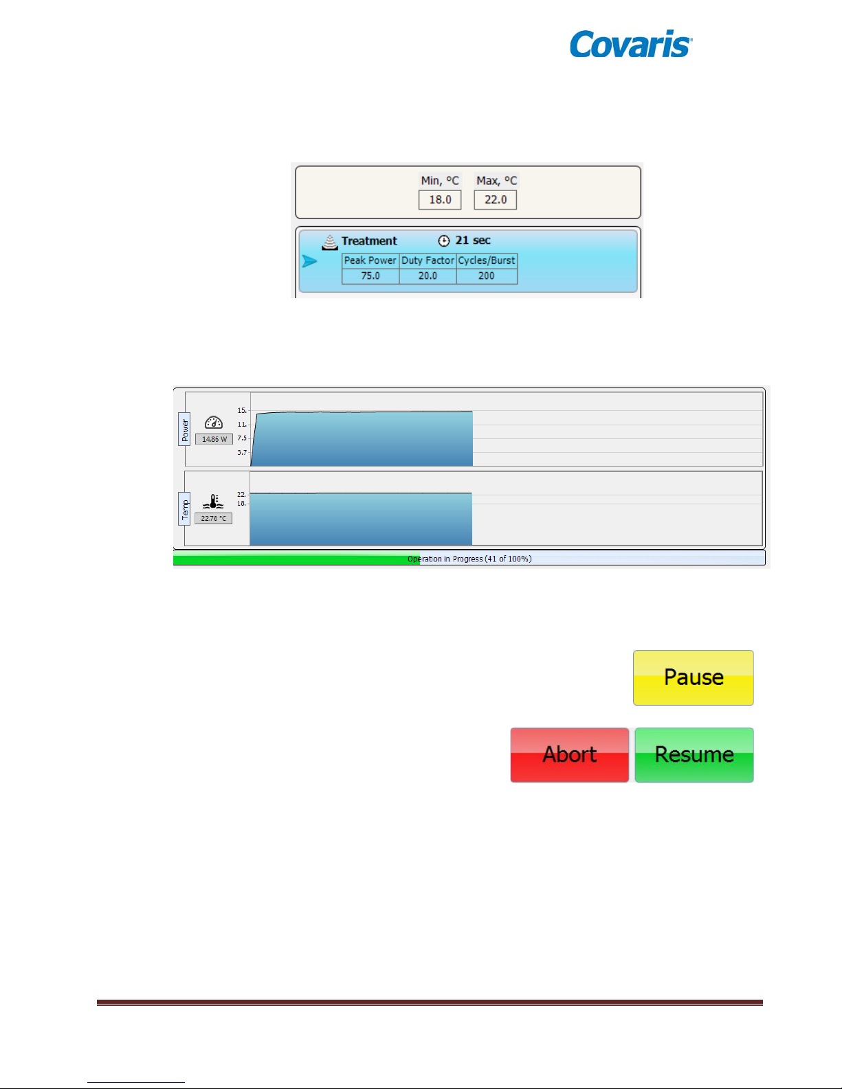
The programmed temperature range and the acoustic treatment details will be posted on the left
side of the Run Screen:
Average acoustic power (in Watts) and water bath temperature will be displayed numerically and
graphically at the lower right corner of the Run Screen, along with a progress bar for the method
being run:
Note that the average Power values will approximate (Peak Power x Duty Factor).
The user may, at any time while running a method, click “Pause” to
interrupt a running method.
When the method is paused, the user may continue
the method by clicking the Resume button, or
terminate the method by clicking the Abort button.
E220 evolution User Manual Page 16
Page 17
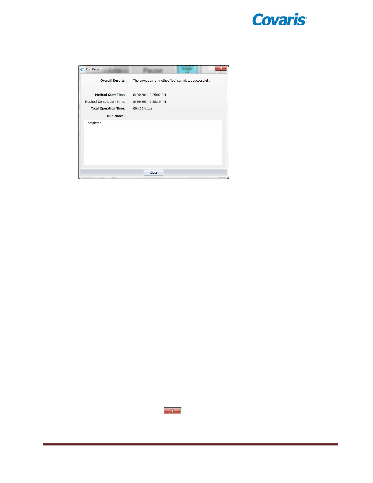
Notes
When the method ends, a Run Results b o x will be posted over the Run Screen.
If necessary, click the mouse in the text entry area to set the focus, then notes may be added
either via the keyboard or an alternative input device. For instance, a barcode reader may be
used to capture data directly from pre-labeled samples.
When finished adding notes, click Close.
Simply open the front door and remove the sample rack.
A new rack may then be loaded into the tray and the process repeated.
If there is additional sample processing to be done, the instrument and SonoLab may be left ON
and operating. If the system will be idle for an extended period of time (e.g. overnight or a
weekend), then please refer to the next section on System Shutdown.
3.4 System Shutdown
If the instrument will be idle for an extended period of time (e.g. overnight or a weekend), shut down
the instrument using the following procedure:
3.4.1 Empty the water tank and purge the degas pump
Turn off the degas pump and click the ‘Service Position’ button to raise the Acoustic Assembly.
Empty the water bath, place it back into the instrument and click the ‘Load Position’ button to
lower the Acoustic Assembly.
Click the Degas Pump control to restart the pump and purge the pump and water lines. The
pump will automatically stop within 10 seconds. Remove and empty the tank again, dry the tank
with a lint-free soft cloth and place it back in the system.
3.4.2 Close SonoLab
Exit SonoLab by clicking on the in the upper right corner. ”Are you sure you want to exit
SonoLab?” will appear.
“Yes” will close the application. “No” will cancel this request.
E220 evolution User Manual Page 17
Page 18
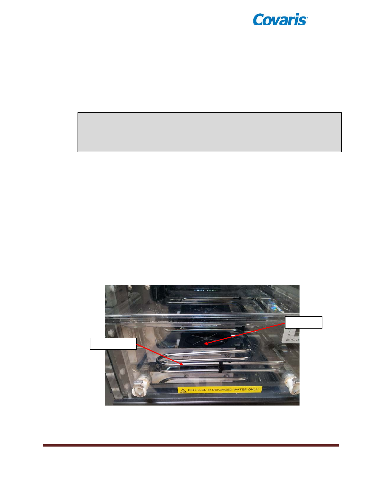
Chiller T ubes
Transducer
3.4.3 Turn System OFF
To shut down the laptop, select Shutdown from the START menu on the Windows screen and
select the option SHUTDOWN. Then the computer will power down.
Power down the instrument using the switch located near the power entry module of the
instrument, at the rear of the right side.
CAUTION: Leaving water in the water bath or degassing lines for an extended time
may promote algal growth in the tank and lines, This growth can int erf er e with water
quality and sample processing.
Change water daily and rinse with a 10% bleach solution monthly.
3.5 Temperature Control
An important principal of the Covaris Focused-ultrasonicator is isothermal temperature control. The
sample is immersed in a water bath which conducts ultrasonic energy while maintaining a stable
sample temperature. Each protocol published by Covaris specifies a desired bath temperature.
The instrument does not control its own water temperature. This must be controlled by adjusting the
set point of an external chiller. This chiller pumps fluid through hoses connected to the left side of
the unit (see Setup) and then through stainless steel tubes immersed in the water bath. These tubes
are visible as part of the Acoustic Assembly, surrounding the ultrasonic transducer.
E220 evolution User Manual Page 18
Page 19
The chiller set point should be programmed a few degrees C below the desired bath temperature.
For example, if a protocol calls for a bath temperature of 7°C, the chiller set point should be adjusted
to approximately 4°C.
During ultrasonic treatments, the instrument continuously measures water bath temperature and
displays this value in SonoLab. Each method has a minimum and maximum temperature defined,
and treatments will be paused if bath water strays beyond these limits. Using the example of 7°C,
the minimum and maximum may be set to 4°C and 10°C, respectively.
If the bath temperature exceeds the method’s programmed temperature limits (in either direction, too
cold or too warm), the Temperature Status indicator on the SonoLab Run Screen will turn red and
the method will pause (unless Temperature has its Override box checked). Such a deviation in
temperature may be indicative of a chiller malfunction or a flow failure in the chiller lines.
CAUTION: To prevent chiller damage, use of a 20% glycol solution in the chiller fluid
is required. Do not use undiluted glycol solution. Please refer to the chiller user
literature.
Use only deionized or distilled water in the instrument bath.
3.6 Degas System
The instrument is equipped with a pump that draws bath water through a degassing process.
Properly degassed water is important for efficient transfer of acoustic energy from
the instrument’s transducer to the sample being treated. If water is detected in the
tank, the pump is automatically turned on when SonoLab is started.
The pump should be allowed to run until the Degas indicator on the Run Screen
turns green (at least 60 minutes) prior to an acoustic treatment.
The pump may be switched off and on with the Degas Pump control on the Run Screen.
Note: the pump can be programmed to stop and start automatically. See ‘Degas Pump Settings’ in
section 4 of this manual.
4.0 SonoLab™ APPLICATION SOFTWARE
SonoLab is an application used to control the Covaris AFA (Adaptive Focused Acoustics) instrument
for processing a sample. It is designed to create, edit, and run a sample processing program called
a method. It has provisions to run, pause or stop a method and view execution histories which
contain a record of key instrument parameter values during a run. It also contains editors for
customizing system settings and performing maintenance functions.
SonoLab provide a series of tabs to access its various features. Each tab will highlight as the cursor
approaches, and a single mouse or touchpad click will access the new screen. Each screen has
secondary screens, indicators and controls. The choices are:
E220 evolution User Manual Page 19
Page 20
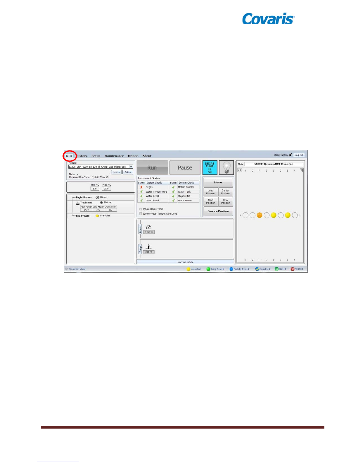
• Run – Select methods to run, run methods, create new or edit existing methods
• History – View system history
• Setup – System setup by user (file management, User Authentication, etc.)
• Maintenance – Instrument parameters set by factory or service personnel
• Motion – Present only when an admin user is logged in. Provides for manual control of
instrument motion system.
• About – System configuration information
The Run tab is the principal user screen for the system. See details presented earlier in this section
on operating the instrument through the Run Screen.
The Run Screen
The Run screen provides access to the Create New Method and Edit Existing Method screens.
4.1 Create and Edit Methods
SonoLab supports the creation of new methods and editing of existing methods from the Run Tab. A
method consists of one or more treatments, delays and message prompts.
4.1.1 To edit or create a new method, click the “Edit…” or “New…” button in the “Method”
window. The Method Editor window will appear.
E220 evolution User Manual Page 20
Page 21
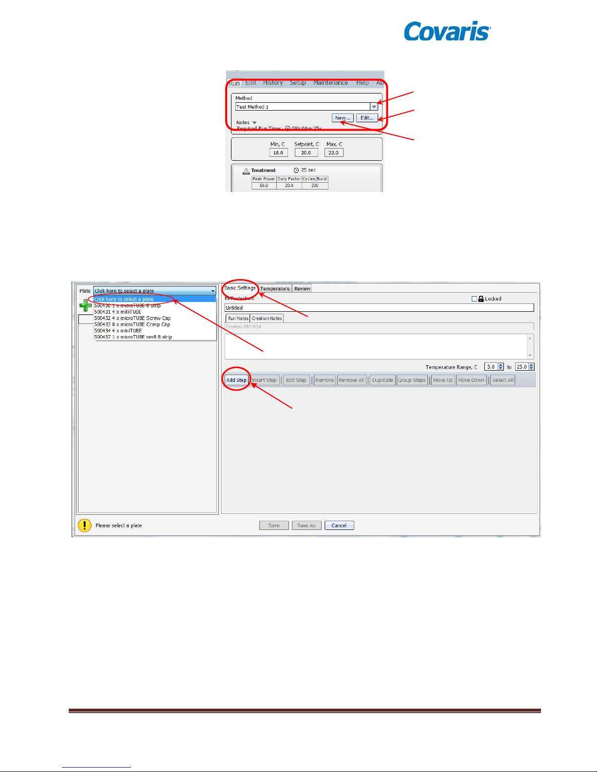
Pull-down list of
methods
Edit the selected method
Create a new method
Basic
‘Select Plate’
Dropdown Menu
Add Step
Controls for creating and editing a method
4.1.2 If creating a new method, in the Basic Settings tab, first, select a plate from the ‘Select
Plate’ drop down. The appropriate plate depends on the tubes being used in your
application.
Create Method / Edit Method Screen
4.1.3 Click the ‘Add Step’ button.
Settings
The Add Method Step window will appear.
The Step Types available from the ‘Step Type’ dropdown list are Process, Delay, Prompt
and Repeat
E220 evolution User Manual Page 21
Page 22
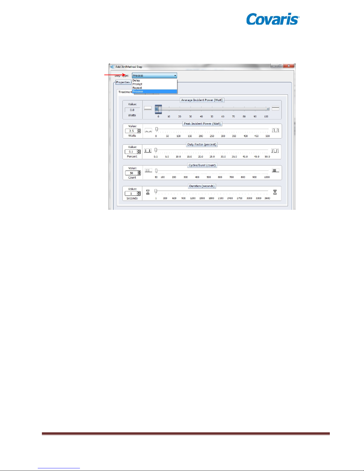
Step Type Dropdown
Choosing Process allows editing of the four acoustic parameters:
‘Process’ step screen showing PIP, Duty Factor, Cycles per Burst, and Time
Treatment parameters can be chosen either by sliding a control left or right, by clicking on
up/down arrows in the value box or by directly editing the Value box. The treatment parameters
are:
Peak Incident Power (PIP)
This is a measure of the instantaneous ultrasonic power applied to the sample. The range is 2.5
to 500 Watts.
Duty Factor
During treatments, acoustic power is “burst” or turned on and off according to Duty Factor and
Cycles per Burst. The duty factor is the percentage of time that the ultrasound signal is applied
to the sample. The minimum value is 0.1% and the maximum is 50.0%
Average Incident Power applied to a sample will be approximately the Peak Power multiplied by
the Duty Factor. For example, if Peak Incident Power is set to 100 Watts and Duty Factor is set
to 15%, the Average Incident Power will be approximately 15 Watts, but will vary with sample
tube type and water level and temperature.
In the E220 evolution instrument, the maximum average power is 100 Watts.
E220 evolution User Manual Page 22
Page 23
Cycles per Burst
The ultrasound is delivered in sinusoidal bursts of ultrasonic energy. Cycles per burst are the
number of cycles of ultrasonic energy to deliver during the on portion of the duty cycle.
Duration
This parameter defines the amount of time, in seconds, that the sample is under a treatment.
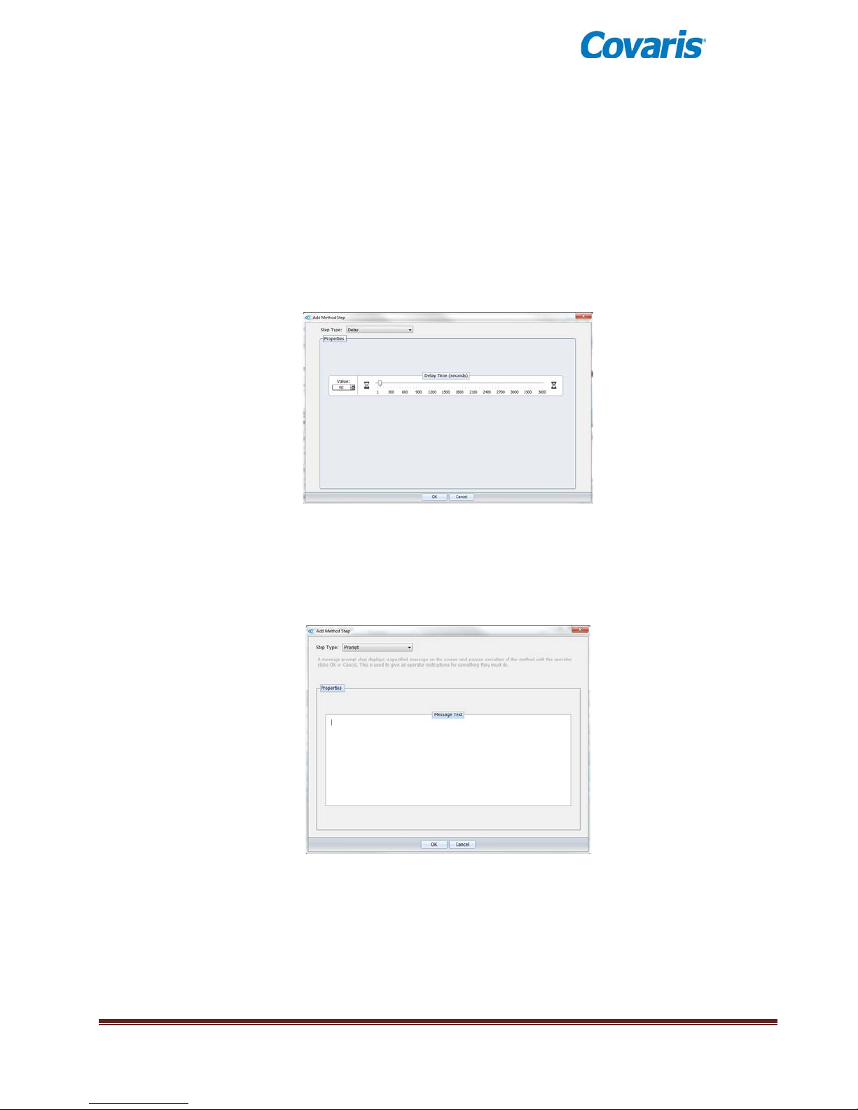
Choosing a Delay step introduces a fixed time delay into a method. The user can set the sample
to settle between two different treatment steps. The delay is specified in seconds.
Add a Delay Step
Choosing a Prompt step will cause a specified message to disp lay on the screen and pauses
execution of the method until the operator clicks OK or Cancel.
Add a Prompt Step
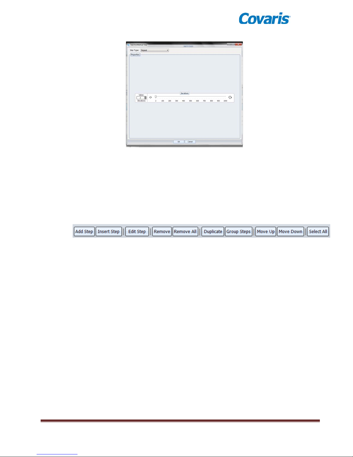
By choosing a Repeat step, the user can create a group and a number of repeat iterations.
Steps may then be moved into this group (see Available Functions below).
E220 evolution User Manual Page 23
Page 24
Add a Repeat Step
When method parameters for the step have been defined, click on OK to save changes and
return to Basic Settings.
4.1.4 From the Basic Settings Tab, once any step exists, general operation buttons are
available for the following functions:
Add Step Allows the user to add a step to the end of the method.
Insert Step Allows the user to select a step and insert a new step either before or
after the selected step.
Edit Step Allows the user to edit the selected step.
Remove Allows the user to remove the selected step.
Remove All Allows the user to remove all the steps. Before the remove, a
confirmation window will appear asking the user if the user wants to
remove all the steps.
Duplicate Allows the user to duplicate a selected step.
Group Steps Allows the user to create a group with one or more steps. A group may
be executed once, or repeated multiple times. A “Create Step Group”
window will appear allowing you to choose the number repeats.
Move Up Allows the user to move the selected step up one level. If the selected step is
already on the top of the list, it has no effect on the method. If the selected step is
in a group, a confirmation window will appear asking if the user wants to move
the step out of the group. This action may also be used to move a step into a
group.
Move Down Allows the user to move the selected step down one level. If the selected step is
already on the bottom of the list, it has no effect on the method. If the selected
step is in a group, a confirmation window will appear asking if the user wants to
move the step out of the group. This action may also be used to move a step
into a group.
E220 evolution User Manual Page 24
Page 25
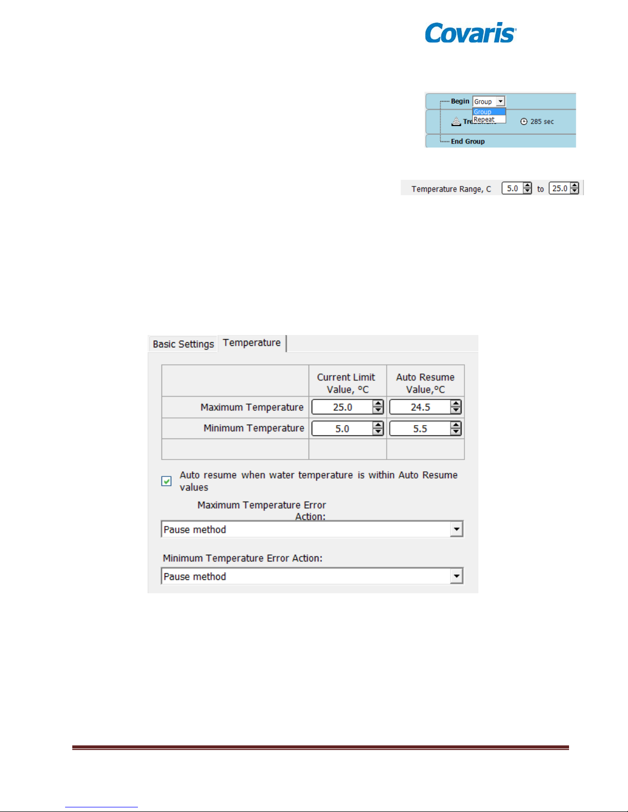
Select All Allows the user to select all steps created.
When a group is created, you have the choice of running this
group of treatment once, or to repeat it multiple times. To
repeat, simply choose Repeat from the Group/Repeat pulldown. The default repeat is 2. Double click on “Begin” to
bring up an Iterations screen. Up to 1000 repeats may be
programmed.
4.1.5 Temperature limits are set by editing the
Temperature Range values in the Basic Settings
Screen. Values may be set as low as 0.5°C and as high as 55.0°C.
4.1.6 If User Authentication is enabled, a method may be locked against editing by other
users. See section 4.5, ‘Enabling User Authentication’ for details.
4.2 Temperature Tab
From the Edit Existing or Create New Method screen, the Temperature tab may be selected for
more advanced temperature settings.
The default temperature settings for a new method are sho wn belo w:
Temperature limits may be changed by editing the “Current Limit Value” boxes.
If, when a method is running, the bath temperature exceeds the Maximum and Minimum limits,
the method will be automatically paused, according to the Temperature Error Action.
If a method is paused due to a temperature fault, the method will automatically resume after the
temperature returns to within the Resume Values.
The automatic resume attribute can be shut off by un-checking the “Auto resume” box.
The Temperature Error Action can be changed to Abort via the pull-down menus. A method
which is aborted, however, cannot be resumed.
E220 evolution User Manual Page 25
Page 26
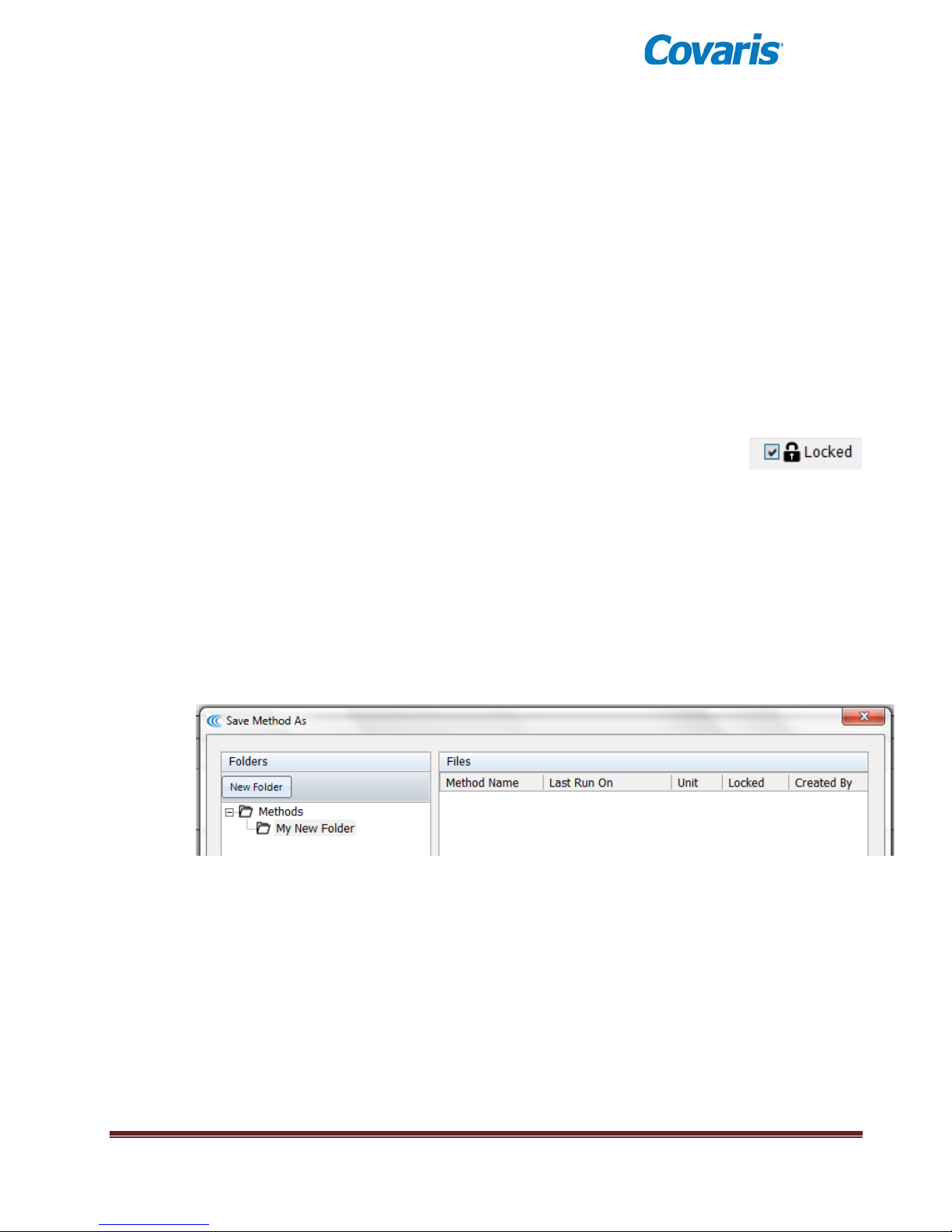
Resume Values are normally 0.5°C inside the Limit Values, but can be edited to create a wider
margin
Changes in a method’s attribute may be saved by clicking Save, Save As, or discarded by
clicking Cancel.
4.3 Saving Methods in Folders
4.3.1 Save: When done creating a new method, type a name in the Method Name box and
click Save to save a method for future use.
4.3.2 Save As: If editing an existing method, clicking Save will overwrite the original method.
Clicking Save As will allow you to save the edited m ethod und er a new nam e and
preserve the original method without edits.
4.3.3 Cancel: To cancel a Save, simply press Cancel. Save, Save As or Cancel will close
the Create or Edit screen.
4.3.4 Locked: If User Authentication is enabled, a Specialist or
Administrator-level user may lock a method against editing by another
user by clicking the Locked icon (upper right corner of the Create or
Edit Method screens). Although an Administrator can override a lock placed on a
method by a Specialist, no other Specialist may edit a locked method.
4.3.5 Folders: The default location for all methods is the Methods folder. To aid
organization, users may create sub-folders under the Methods folder. To create a subfolder, click Save As. In the Save Method As dialog, click New Folder. A New Method
Folder dialog will appear. Enter Folder Name, then click OK.
The new folder will appear under Methods as shown below. Additional subfolders may
be created by highlighting Methods and clicking New Folder, or by highlighting any
subfolder and clicking New Folder.
E220 evolution User Manual Page 26
Page 27
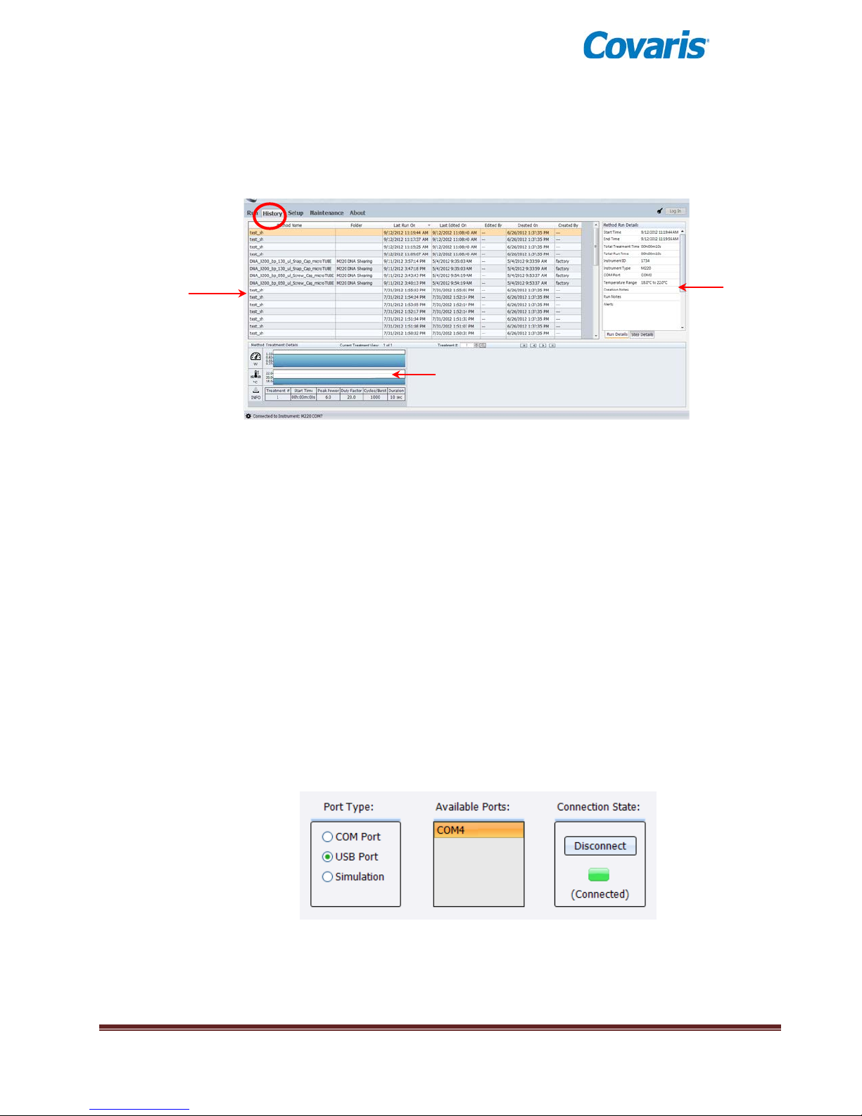
Method Run Details
Average Power and
Temperature Graph
Runtime Information
4.4 History Tab
The History tab shows the history of every method performed on the instrument. It displays the
selected method’s runtime information and run details. A graph of the actual average power and
temperature during each treatment step is stored.
History Tab
4.5 Setup Screen
The system setup editor allows an operator to:
4.5.1 Communications
SonoLab will automatically connect to the instrument if the unit is powered on and linked by a
USB cable. No action by the user is required. The typical connection method will be “USB
Port”.
• Configure the communication port used to control the instrument
• Enable/disable user authentication and configure us er acc ounts
• Specify folders used to save methods, history files, and log files
• Schedule the degas pump auto start/stop time.
The Communications tab allows the user to manually connect with the instrument if automatic
connection fails. If connection problems persist, please contact Covaris Service for assistance.
E220 evolution User Manual Page 27
Page 28
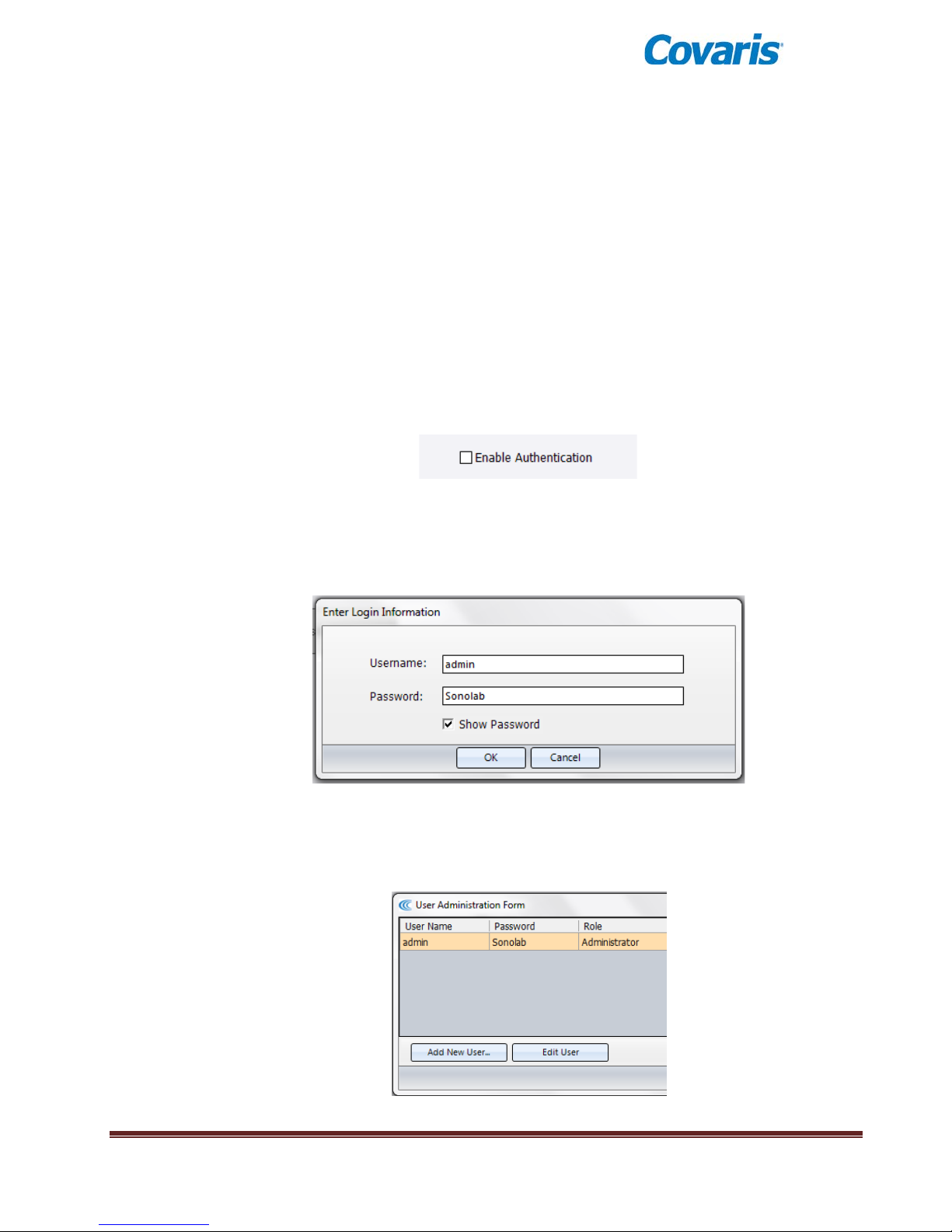
If desired, SonoLab may be placed into its Simulation mode. This disconnects SonoLab from
the instrument, but allows the user to run, edit or create methods as if the software were
connected.
4.5.2 Enabling User Authentication
The User Authentication feature allows a laboratory administrator in a multi-user laboratory to
establish authorized users with three levels of access to methods and settings.
By default, authentication is disabled and the Log In button in the upper right corner of the
SonoLab screen is disabled. This is the typical configuration SonoLab – all users have equal
access to methods and settings.
If User Authentication is enabled by an administrator, users log in under their User Name and
Password when working with the system. (Users not logging in will have the lowest user rights
of an anonymous Operator.)
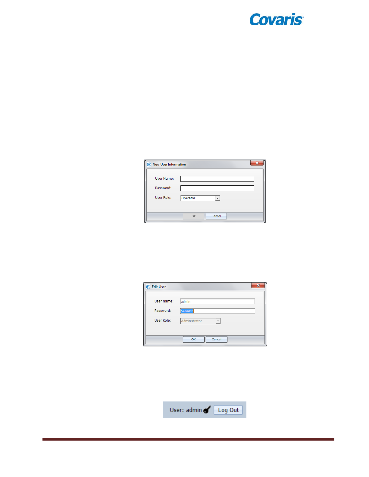
To enable User Authentication, click the ‘Setup’ tab, then select ‘User Authentication’ and leftclick the User Authentication check box:
Upon clicking the box, a log in dialog will appear. The only users allowed to enable or disable
User Authentication are Administrators. Every system has a user named “admin”, who is an
Administrator and, in a new system, is given the default password “Sonolab”.
Log in as “admin”, as shown below. Please note that both Username and Password are case
sensitive.
Click OK. The Login box will disappear, the Authentication checkbox will be enabled, and the
‘User Administration’ button will become active.
Click on ‘User Administratio’n. The User Adminstration Form will appear:
E220 evolution User Manual Page 28
Page 29
An Administrator may create, edit or remove three types of users:
• An Operator - is only allowed to run existing methods. An operator can review the
history screens and system configuration information but cannot edit an existing method,
create a new method, or modify the system operating mode.
• A Specialist - may perform all the functions of an operator. In addition, a Specialist is
allowed to create new methods and edit existing methods, unless those methods h ave
been locked by another Specialist or Administrator user.
• An Administrator - may perform all the functions of a Specialist. In addition, an
Administrator has the ability to configure the system’s operating mode (enable or disable
User Authentication and perform file management and maintenance functions). An
Administrator can additionally create, edit or remove user accounts.
To create a new user, simply click Add New User… and type the new User Name, Password
and User Role (Operator, Specialist, Administrator) into the New User Information dialog, and
click OK
To edit an existing user, simply highlight the user in the User Administration Form, and then click
Edit User. An Edit User dialog wi ll appear . As Adm inist rator , you m a y edit the Pass word and/ or
User Role. The only user that you cannot delete or change User Role is the original “admin”
Administrator. You may, however, change the “admin” password and click OK to establish
security for the “admin” user account, as shown below.
To remove a user, highlight the user and click Remove User(s).
From the User Administration Form, click on Save to preserve any edits and return to the User
Authentication tab. To secure the system, make note of the admin password, leave User
Authentication enabled, and log out of the admin account by clicking on Log Out (upper right
corner of the SonoLab screen:
E220 evolution User Manual Page 29
Page 30
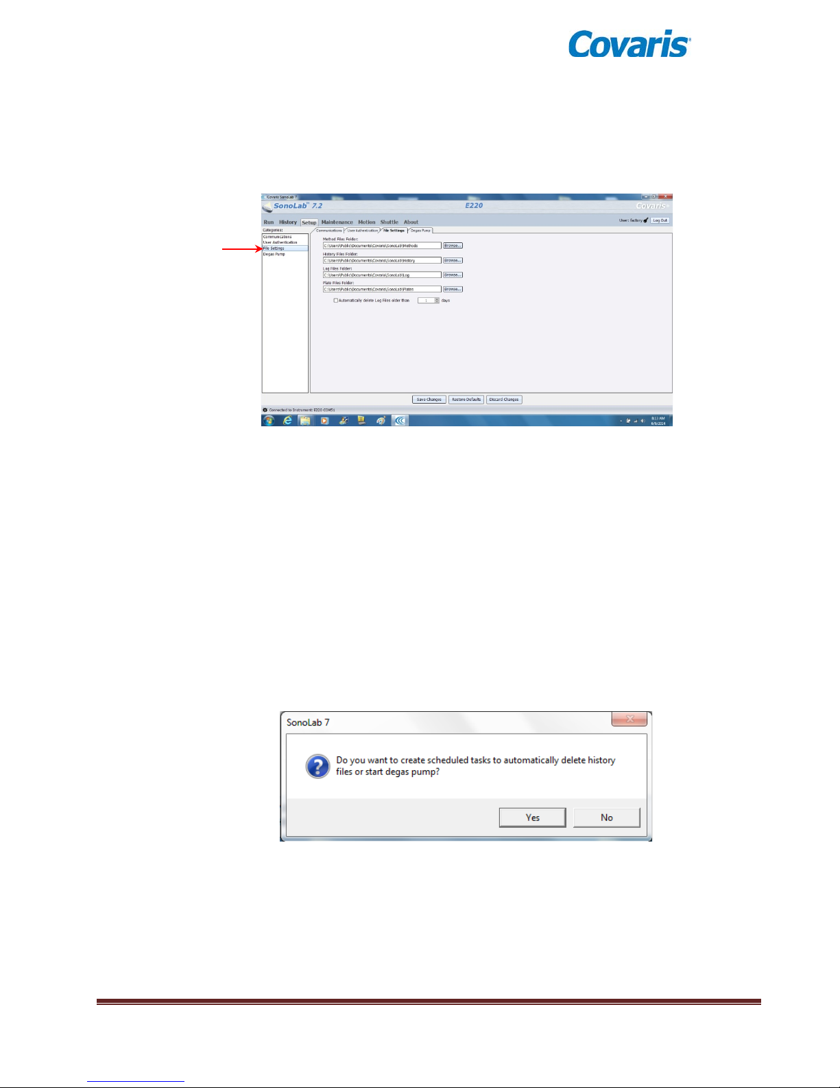
4.5.3 File Settings
By selecting the File Settings tab, users may change file locations or set up a scheduled task to
automatically delete old log files.
To change a File Setting:
• Log in as an Administrator.
• Navigate to the Setup/File Settings tab.
• Click the “Browse…” button for the path to be edited.
• Select or create a new folder for a new location and click OK.
• Click Save Changes. Click OK on “Successfully Save the System Settings”.
• For this change to take effect, you must exit and restart SonoLab.
To enable or change the automatic Deletion of Log Files:
• Enable User Authentication and log in as an Administrator
• Navigate to Setup/File Settings to enable or disable automatic file deletion, and/or edit
the number of days that files are preserved.
• Click Save Changes.
• Click Yes and log into Task Scheduler Login under your Windows user name. The
default Windows user name for computers shipped from Covaris is “Covaris”, with no
password.
• SonoLab will restart and, if requested, Windows Task Scheduler will delete files at 7:00
pm (19:00) according to the configuration saved under File Settings.
E220 evolution User Manual Page 30
Page 31
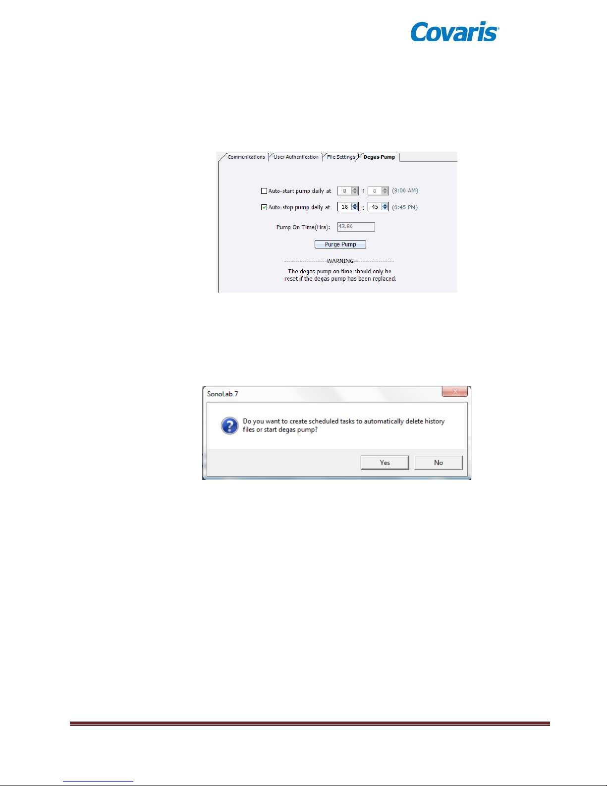
4.5.4 Degas Pump Settings
This section allows a user to set up schedules to automatically start and stop the degas pump
daily at a scheduled time. User Authentication must be enabled, as an Administrator is required
to edit these settings.
To enable or schedule pump tasks:
• Enable User Authentication and log in as an Administrator
• Navigate to Setup/Degas Pump to enable or disable automatic pump tasks.
• Click Save Changes. The following message may appear:
• Click Yes. The Windows Task Scheduler Login window app ears . Log in u nder your
Windows user name. Computers provided by Covaris have a single Windows user,
“Covaris”, with no password.
• Click OK on “Successfully Save the System Settings”.
• For this change to take effect, you must exit and restart SonoLab.
• Upon restarting SonoLab, the following message will appear:
• SonoLab will restart. Windows Task Scheduler will turn the degas pump on or off at the
requested time. The instrument must be switched ON and connected to the laptop for
these tasks to occur.
Users may also manually run the degas pump for 10 seconds by clicking the “Purge Pump”
button. This drains water from the pump and the lines connecting the pump to the bath.
E220 evolution User Manual Page 31
Page 32
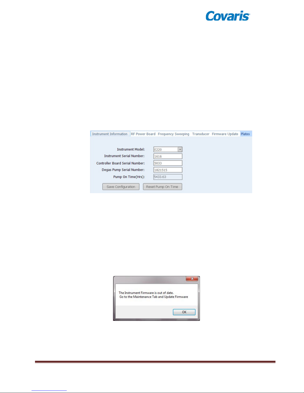
4.6 Maintenance Screen
Selecting the Maintenance tab or category allows an operator to view:
• Instrument Information
• RF Power Board Calibration
• Frequency Sweeping Parameters
• Transducer Parameters
• Firmware Update
• Plates
An example of one of the informational screens is shown below:
RF Power Board Calibration, Frequency Sweeping Parameters, and Transducer Parameters are
typically used only by Covaris service per sonnel, and are read-only screens for SonoLab users.
4.6.1 Firmware Update
On occasion, it is necessary for Covaris to make changes to the firmware that operates the
instrument. When SonoLab connects to an instrument, it checks the version of firmware that is
running on that instrument. If the instrument’s firmware is out of date, SonoLab will alert the
operator and suggest that a firmware update should be performed. See the Firmware Update
section of Appendix C for detailed instructions.
Firmware Out of Date Alert
E220 evolution User Manual Page 32
Page 33
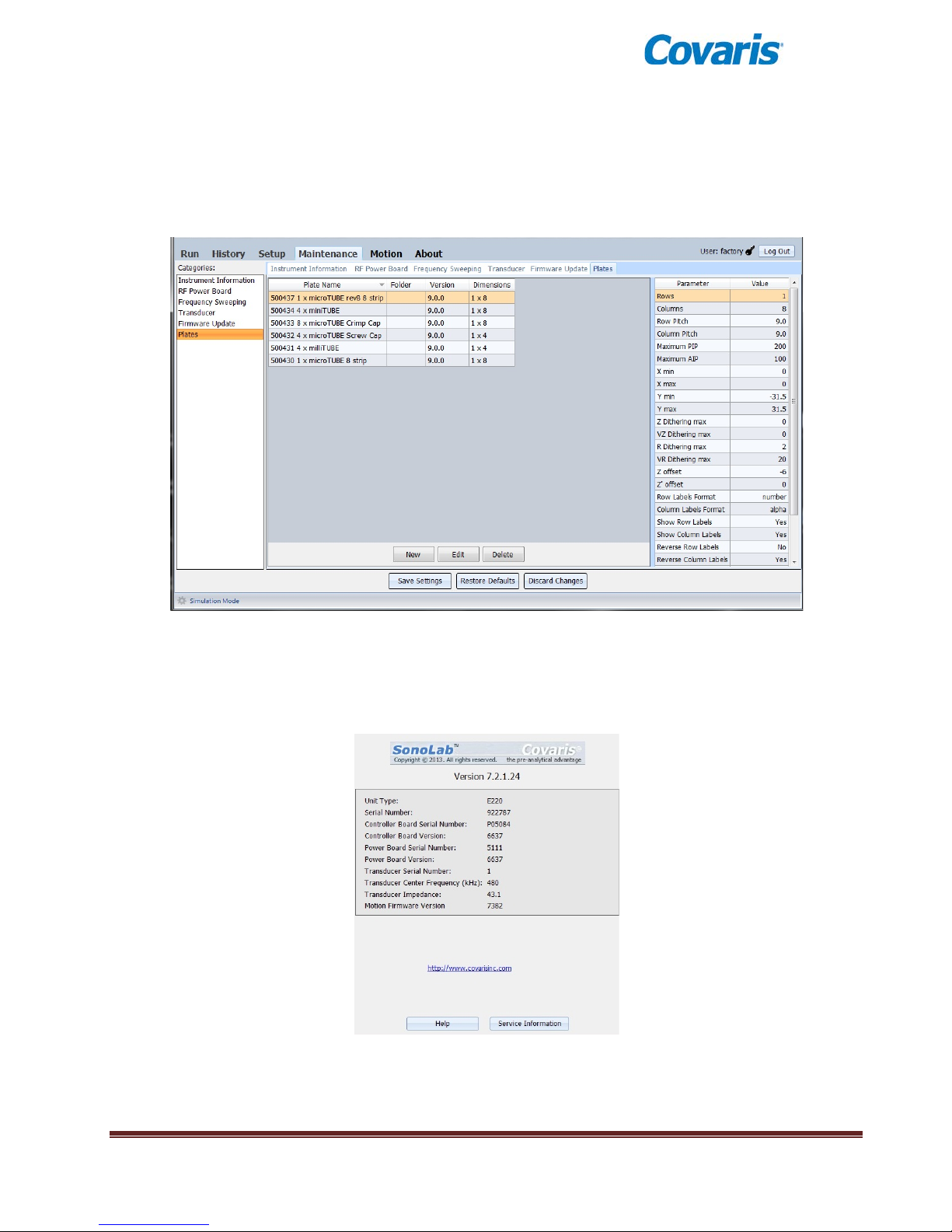
4.6.2 Plates
The ‘Plates’ item provides a well plate editor, displaying parameters for the well plates available
for use with the instrument. User “admin” can create new plate definitions and edit those
definitions, but not the factory definitions delivered with the instrument. Users should contact
Covaris personnel before creating new well plate definitions.
Plate Editor Screen
4.7 About Tab
The About Tab provides the user with basic information about the instrument such as serial number,
software version, and board serial numbers. Contact information for Covaris is also displayed.
Clicking Help provides detailed Applications and Service information.
E220 evolution User Manual Page 33
Page 34
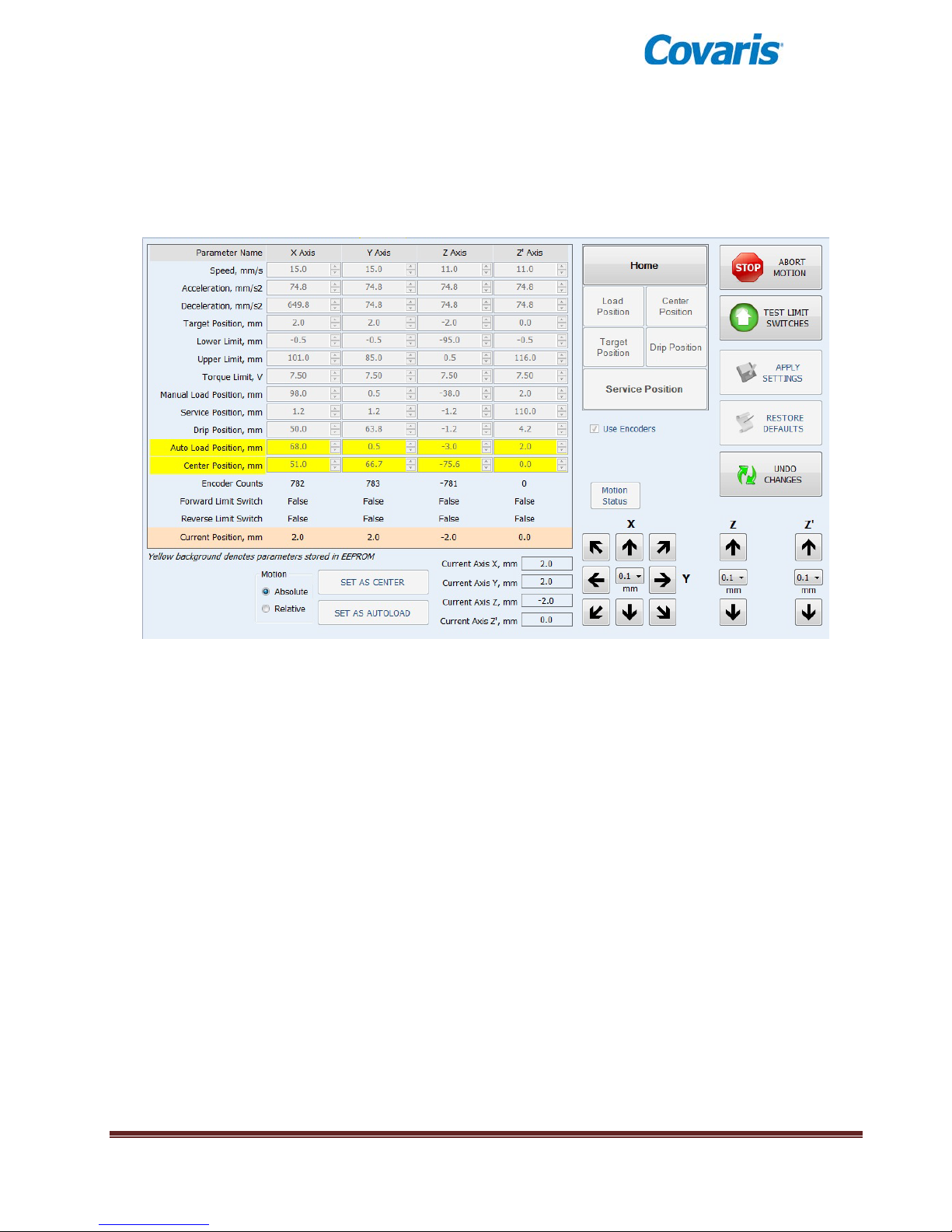
Clicking on Service Information creates a file, Status.ZIP, which captures status files from the
instrument. This can be emailed to Covaris to aid in diagnosing any problems.
4.8 Motion Tab
• The left half side of the Motion screen shows motion parameters and predefined sample tray
positions. These are read-only for non-Covaris personnel.
• The ‘Home’ button initializes the motion system. The ‘Load Position’, ‘Target Position’,
‘Center Position’, ‘Drip Position’, and ‘Service Position’ buttons move the sample tray to
predefined positions.
• The ‘Stop’ button halts movement of the motion system.
• The Test Limit Switches button is a troubleshooting tool. As the name implies, it tests the
motion system limit switches and reports any problems encountered.
• Apply Settings, Restore Defaults, and Undo Changes buttons are for service personnel only.
• The navigation arrows permit moving the sample tray and transducer discrete distances
from .1 millimeter up to 50 millimeters. The specified distance is selected from the drop
down list between the arrow buttons. The X and Y buttons move the sample tray forward
and back and left and right. The Z buttons move the sample tray up or down. The Z`
buttons move the transducer up or down.
E220 evolution User Manual Page 34
Page 35

Models
E220 evolution
Bench-top; high intensity acoustic transducer, temperature monitoring
device, circulation pump, water bath with safety enclosure
Treatment Power:
500 Watts Peak Incident Power, 100 Watts Average Power
Dimensions:
23” W x 30” D x 19” H (59cm x 76cm x 48cm)
Weight:
approximately 110 lbs. (50 kg)
Power Requirements:
100-240 VAC 500 VA maximum, 50-60Hz
Ambient Temp. Range:
19ºC to 25ºC (66ºF to 77ºF)
Ambient Humidity Range:
30% to 70%
Regulatory Labeling:
CE, ETL Mark (for Product Safety), WEEE
Complies with Low Voltage Directive 2006/95/EC. Certified to
Measurement, Control and Laboratory Use, Part 1: General Requirements”
Complies with Class A Industrial/Scientific/Medical (ISM) equipment under
requirements for the USA and ICES-003 Class A for Industry Canada.
Water Bath:
Temperature Alarms:
Distilled or deionized water only
Can be programmed from +0.5°C to +55.0°C
Computer:
Notebook computer typical
Operating System:
Microsoft Windows XP SP3, 7 or 8
Application Software:
Covaris SonoLab 7
Data Input:
Keyboard, mouse
Chiller re-circulating system - may be purchased independently or from
supplied.
5.0 SYSTEM SPECIFICATIONS
Treatment System:
Safety:
EMC:
Chiller:
IEC/EN/ANSI/UL 610 10-1:2004 and CAN/CSA C22. 2 No. 6101 0-1:2004,
2nd Edition “Safety Requirements for Electrical Equipment for
EN 61326-1:2005, EN 61000-3-2:2004 and EN 61000-3-3:1995 for EU
EMC Directive 2004/108/EC. Also FCC Part 15 Class A radio emissions
Covaris. Connect with the 3/8 inch I.D. hoses and quick connect fittings
E220 evolution User Manual Page 35
Page 36

6.0 MAINTENANCE
6.1 Cooling Air Intake
Periodically, unplug the unit and remove any obstruction to the fans and air vents on the rear panel
to ensure that objects are not restricting the flow of air.
6.2 Water Bath
6.2.1 Recommendations for Daily Maintenanc e
Only distilled or deionized water should be used to fill the water bath. To avoid algae growth, the
water bath should be emptied, the degas lines purged, and the tank dried prior to overnight or
weekend storage, as described in System Shutdown in Section 3.
If a Water Conditioning System (WCS) is used, the bath needs to be changed only once per
month.
6.2.2 Recommendations for Monthly Maintenance
Periodically, the water bath and degas sing lines sho ul d be rinsed wit h a 10% solution of Clorox
bleach. The resultant sodium hypochlorite solution is ~ 0.5% NaOCl. Perform the following
bleaching protocol:
1) Turn off the WCS (if present) and disconnect its hoses from the front of the water tank.
2) Fill the tank with approximately 450 ml of household Clorox and the rest with DI water.
3) Operate the degas pump for approximately 5 minutes.
4) Empty the bleach/water solution.
5) Place the empty water tank back into the instrument and operate the degas pump for a few
seconds to purge the bleach solution from the pump lines and housing.
6) Empty the tank, rinse, and fill with fresh DI water.
7) Place the water tank back into the LE220 and operate the degas pump for 3 minutes.
8) Repeat steps 6-7 2x more.
9) Fill the tank with clean DI water, reconnect and power on the WCS. Allow water to degas for
at least a half-hour with the chiller turned off.
6.3 Transducer
Use care when handling the transducer. Permanent damage could result if anything is dropped onto
the face of the transducer or if the face of the transducer is damaged.
If drying or cleaning the transducer face, use a soft lint-free cloth. If broken glass must be removed
from the transducer surface, carefully pick any shards off the surface with tweezers. Do not rub
them away, as this may scratch the transducer surface.
6.4 Safety System
Test the system periodically. Verify that the acoustic treatments are disabled when the ‘ Stop’ button
is pressed, or if the water level in the tank is too low.
WARNING: Any failure of the Safety System must be reported immediately to
Covaris. DO NOT attempt operation if the Safety System is malfunctioni ng .
6.5 Degassing System
The degassing pump should not be run without a water bath. Extende d runni ng w ithout water will
cause the pump head to wear out. If water is lo w, the pum p will shut of f within 10 seconds .
E220 evolution User Manual Page 36
Page 37
When the pump is running, verify that there are small bubbles coming from the end of the outlet
nozzle. If you suspect that the system has become clogged, please contact Covaris for assistance.
There is a small inlet tube that can be removed and cleaned.
For long-term storage, water should be removed from the degassing pump lines. Follow the System
Shutdown procedure in Section 3.
Degassing the instrument is best performed on room temperature water, as water below about 15
degrees C does not degas as efficiently. Typically, the operator should begin degassing
approximately 30 minutes prior to powering on the chiller. If it is necessary to have the instrument
available first thing in the morning, degassing and chilling may be started the previous evening.
There are no issues with leaving the instrument powered on overnight.
6.6 Cleaning the System
Clean the external surfaces of the equipment as necessary with a damp lint-free cloth. Rinse the
water tank with clean water and wipe dry with a lint-free cloth.
CAUTION: Do not employ isopropyl alcohol, ammonia-based or abrasive cleaners on
the water tank, as these will damage the acrylic surfaces.
E220 evolution User Manual Page 37
Page 38

7.0 TROUBLESHOOTING
This section provides a list of symptoms and recommended actions that may be taken to correct
simple problems. Please contact Covaris or your local representative for assistance with any
problem.
• Instrument will not connect to SonoLab (“Disconnected” displayed at top of screen):
o Verify that the instrument is ON.
o Verify that the USB cable is connected at both ends and undamaged.
o Go to SonoLab Setup tab, choose Communications, and verify that the status is “USB
Port” and “Connected”. If not connected, click on Connect button to attempt manual
connection.
o Close and restart the SonoLab application.
o Go to Windows Device Manager (right click on Computer, then Properties) and verify
that Windows is recognizing the instrument, and that device drivers are properly
installed. Under Ports (COM & LPT), there should be four devices listed:
Covaris RF Controller (COM3)
Covaris RF Controller (COM4)
Covaris RF Controller(Port3&4) (COM5)
Covaris RF Controller(Port3&4) (COM6)
The COM assignments may be different from those listed above (e.g. COM 7, 8, 9. 10) .
Under Universal Serial Bus Controllers, there should also be four devices listed:
Covaris RF Controller Board
Covaris RS-485 Port
Covaris Serial Port 2
Covaris Serial Port 3
Each of these devices should be listed. If any appear with a yellow “!” symbol, right-click
and try to re-install the device driver.
• Safety Interlock or Sensor Failures (Water Level, Water Tank Present, Door Closed, Water
Temperature). These are generally failures that require the attention of a Service technician, but
please verify the following items before contacting Service:
o Water Level: Verify that the water level in the tank is at or above the “0” mark on the
WATER LEVEL label. Verify that the Acoustic Assembly is fully lowered into the tank.
o Tank Present: Verify that the Acoustic Assembly is fully lo wer ed into the tank. Verify
that the tank is slid fully into the enclosure, so that the magnet embedded at the rear of
the tank can be sensed. Verify that the magnet is embedded in the rear of the tank.
o Door Closure not recognized: Verify that the door interlock is not bypassed.
o Water Temperature limits being reached, or inaccurate temperature readings: If the
water is running hot, verify that the chiller is operating and that its fluid (typically a 80%20% water-glycol mix) is circulating through the instrument’s chiller coils. Program the
set point of the chiller to a lower temperatur e and v erif y that the instrument’s coils get
cold. Use a separate thermometer to verify the true temperature of the bath.
• Biological or chemical results (e.g. DNA shearing) not as expected:
o Verify that the average power values reported by SonoLab are approximately correct.
The typical average power is a few percent below the value “Peak Incident Power”
multiplied by “Duty Factor”. For example, if PIP=200 Watts and Duty Factor is 10%,
then an expected power reading would be just below 20 Watts.
o Verify that the water temperature is correct and that the water is clear and free of algae
or other particulates. Perform a 10% solution bleaching protocol if this has not recently
been done.
o Verify that the degassing pump is operating (observe the pump outlet on the left side of
the tank – when the pump is running there should be occasional bubbles exiting the
pump outlet tube). Also examine the inlet “dip tube” visible from the right side of the
E220 evolution User Manual Page 38
Page 39

tank. The inlet holes (very small drilled holes in the side of the tube) should be free of
obstruction.
o If possible, please independently verify your analysis equipment. Covaris has DNA
shearing verification kits available. Please contact Covaris applications support or your
local representative for assistance.
• SonoLab reported Power Level is lower or higher than expected:
o Verify that the average power values reported by SonoLab are approximately correct.
The typical average power is a few percent below the value “Peak Incident Power”
multiplied by “Duty Factor”. For example, if PIP=200 Watts and Duty Factor is 10%,
then an expected power reading would be just below 20 Watts.
o In SonoLab, go to Maintenance, then Transducer, and record the displayed values.
o In SonoLab, go to the About tab and click Service Information. This will create a ZIP file
on the desktop that can be emailed to Covaris or your local representative.
o Contact Covaris or your local representative and provide the information listed above.
• Degas Pump problems:
o Verify that the water is clear and free of algae or other particulates. Perform a 10%
solution bleaching protoco l if this has not rece ntly been done.
o Verify that the degassing pump is operating (observe the pump outlet on the left side of
the tank – when the pump is running there should be occasional bubbles exiting the
pump outlet tube). Also examine the inlet “dip tube” visible from the right side of the
tank. The inlet holes (very small drilled holes in the side of the tube) should be free of
obstruction.
o If the degas pump makes a very loud noise when operating, it may need to be replaced.
• Particulates in bath water
o Change the bath water with fresh DI water
o Perform a 10% solution bleaching protocol if this has not recently been done.
• Tube Breakage
o Verify that the acoustic parameters being employed are correct and that recommended
PIP wattage levels for the tube are not being exceeded.
o Verify that average power levels are approximately correct (see Power Level).
o For microTUBEs, verify that the Intensifier (inverted cone below the tube) is in place and
aligned with the tube.
• RF Board Limits Exceeded Error:
o If Peak Incident Power is set to values above 400 Watts, intense acoustic reflections
may cause an overload in the electronic circuits driving the transducer. To protect the
drive circuits and transducer, the system may shut down and post a message, “RF
Board Limits Exceeded RF Error is Present”. Should this error appear, please retry your
application with the following modifications:
Fill the sample tube to eliminate splashing and large bubble formation in the
sample
Replace the existing bath water with new, clean bath water
Lower the PIP (Peak Incident Power) – this is often more effective than applying
very high power.
Repeat the method to verify that overload problems have been mitigated. If not, please
contact Covaris or your local representative.
Technical Support – Telephone (+1 781 932 3959) during the hours of 9:00am to 5:00pm, Monday through
Friday, United States, Eastern Standard Time (EST), or e-mail queries to [email protected]
.
E220 evolution User Manual Page 39
Page 40
DEFINITIONS
All Covaris instruments are rigorously tested at the Manufacturing Facility prior to shipment. This is done to
Appendix A: Suggested E220 evolution IQ / OQ / PQ
ensure that your Covaris device is of the highest quality and meets your needs for consistent, efficient, and
reliable Sample Preparation.
In the event that you require a method for independent verification of your Covaris Instrument, a set of
recommended IQ/OQ/PQ activities and requirements are provided in the following Checklist format. If desired,
this Checklist can be completed and retained for your personal records. These suggested activities are basic in
nature, and intended only for high-level instrument qualification. Given your situation, you may wish to
supplement these activities with application-specific performance activities and acceptance criteria.
IQ (Installation Qualification): ensure correct instrument has been delivered and installed in accordance with
manufacturer’s requirements
OQ (Operation Qualification): ensure instrument is functioning in accordance with specif icat ion and al l
measurement sensors, safety interlocks, and software operate as intended
PQ (Performance Qualification): demonstrate the instrument continues to meet specification appropriate to routine
use
E220 evolution User Manual Page 40
Page 41
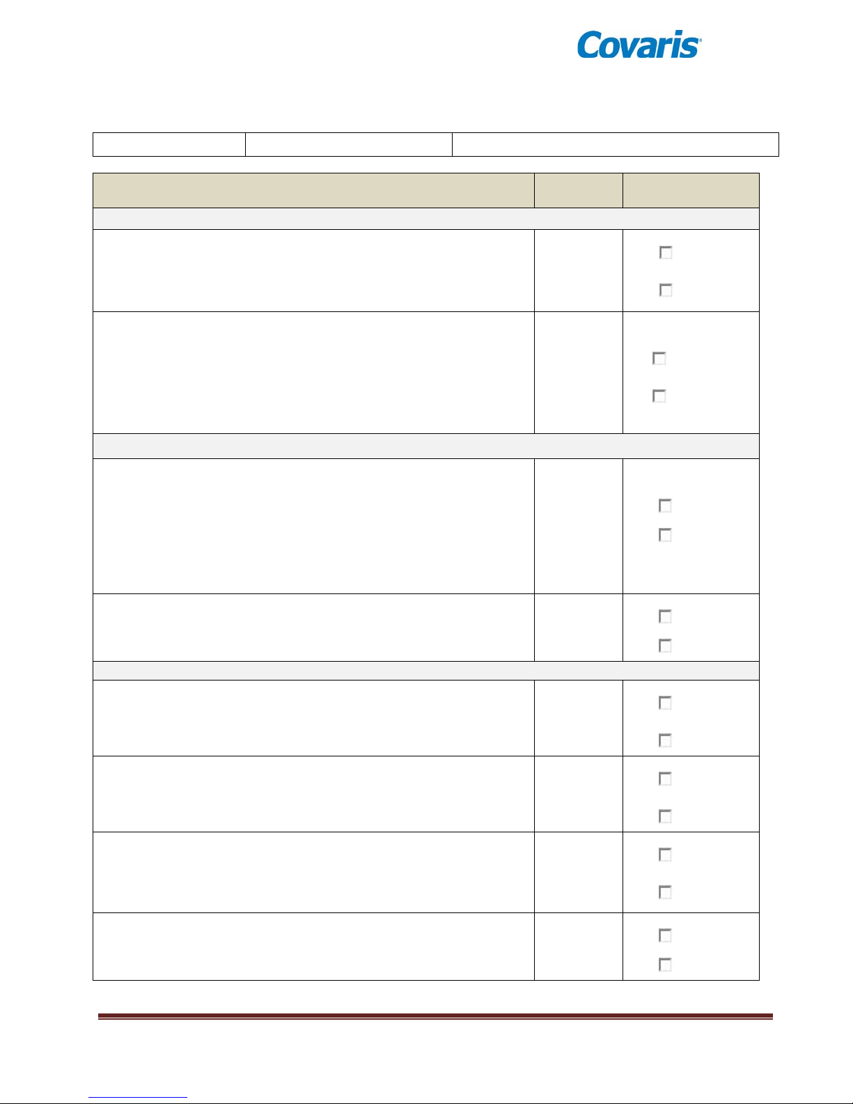
DATE:
INSTRUMENT S/N:
COMPLETED BY:
Section 1: Shipping Conte nts and Instrument Condit ion
Instrument is successf ully unpacked and all ite ms noted in Packing List
YES
NO
There is no damage evident to the instrument or accessories.
YES
NO
Section 2: Verify Proper Site Cond itions
Adequate space and ventil ation are present for t he i nst ruments, and the
YES
NO
YES
NO
Section 3: Component Assembly
YES NO
YES
NO
Connect Chiller to hoses t o the instrument quick-co nnect fittings and
YES
NO
Power ON instrument with ON/OFF Switch and verify:
YES NO
E220 evolution INSTALLATION QUALIFICATION (IQ)
Action / Requirements Ref. Section Requirement Met?
are present.
Denote any missing items here: _______________________________
If damage is present:
Description of Damage:________________________________
Corrective Action: ____________________________________
room conditions (temp, humidity, etc.) are within recommended limits
for the device per the User Manual.
If unacceptable:
Non – Conformity: _____________________________________
Corrective Action: ______________________________________
Three (3) appropriate pow e r outlets are available for the device, laptop,
and accessory Chiller (if necessary).
Connect the laptop and i nst rument to line power . The line cords are
verified to be in proper condition and match the Wall Outlet. Connect
laptop to instrument vi a USB Cable.
Remove the water tank from instrument and take off plastic packaging.
Verify there are no visible cracks or damage. Do not fill tank with
water yet, but plac e back into the instrument.
fill reservoir for Chiller. Plug in Chille r and turn on (if not already on).
Verify the Temperature Se t Point can be adjusted and set it below 20C.
Verify that the water chills over time.
1) Instr ument Fans ar e now audible.
2) Internal instr ument lights above plate sample holder turn on.
E220 evolution User Manual Page 41
Page 42
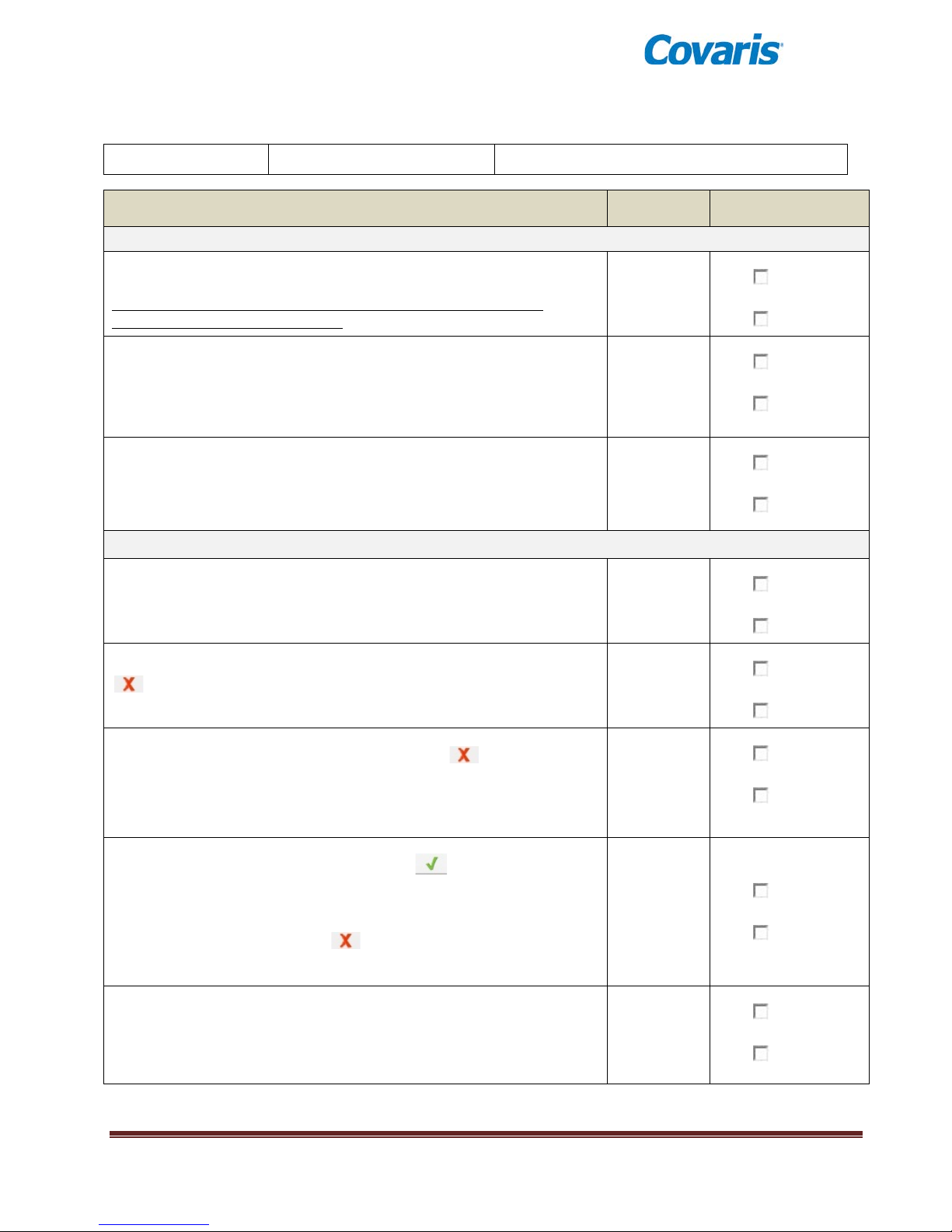
DATE:
INSTRUMENT S/N:
COMPLETED BY:
Section 1: Instrument Co nnection
YES NO
YES
NO
YES
NO
Section 2: Sensor / Safety Interlock
YES NO
YES
NO
Press and hold Green ‘DOOR’ button at the front of the instrument and
YES
NO
YES NO
YES NO
E220 evolution OPERATIONAL QUALIFICATION (OQ)
(1 of 2)
Action / Requirements Ref. Section Requirement Met?
Verify computer is connected to instrument via USB cable provided.
Power on the computer and log in (as required).
Note: If Laptop is not provided by Covaris, refer to SonoLab / Driver
installation sections of User Manual.
Double-click the ‘SonoLa b’ shortcut on the computer desktop; verify the
application starts and software requests a ‘HOMING’ sequence be
performed. Follow instructions to perform ‘HOMING’.
After motion initialization is completed, verify the SonoLab software
recognizes the instrument and indicates the instrument type at the top
right of the screen.
Verify Temperature is displayed in SonoLab and is approximately the
same as the ambient te mperature (since tank is empty).
Bath Temp Reading: ______ °C
With transducer in position in empty tank, verify t he presence of a red
next to ‘Water Level’ on the SonoLab ‘Run’screen.
open treatment door. Verify the presence of a red next to ‘Door’ on
the SonoLab ‘Run’ screen. Leave the door open and click ‘Load Position’
button on the ‘Run’ scree n. Verify SonoLab does not allow this
command.
Shut door and verify t he presence of a green next to ‘Door’ on the
‘Run’ screen. Click ‘Service Position’ button. When transducer and
sample mechanical assemblies are above tank, open the instrument door
and pull water tank back from instrument a few inches (or completely).
Ensure the the presence of a red next to both ‘Door’ and ‘Water
Tank’ on the ‘Run’ screen.
Fill Water Bath wit h D I or Distilled water betwe e n 10 and 15 marks on
left-hand FILL Side of water level label and install f il le d water tank back
into instrument.
E220 evolution User Manual Page 42
Page 43
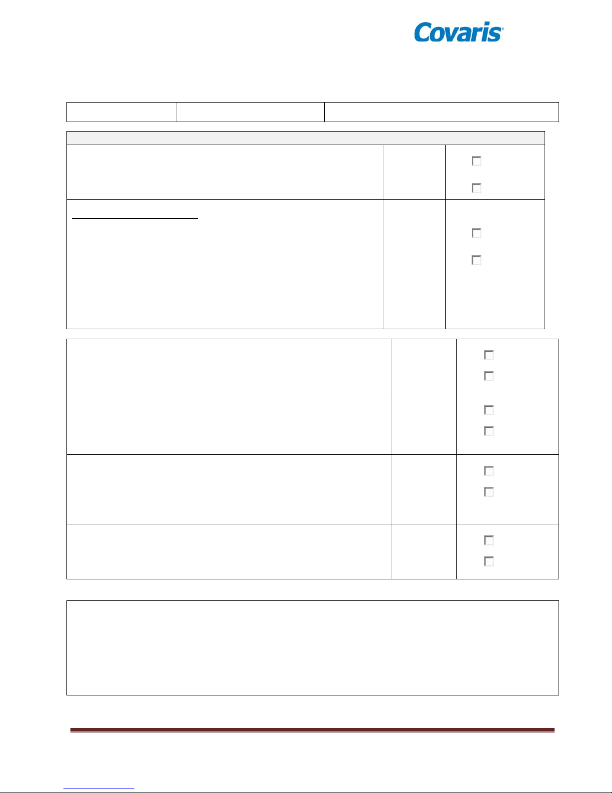
DATE:
INSTRUMENT S/N:
COMPLETED BY:
Section 3: Degas / Run Method
YES NO
YES
NO
YES
NO
YES
NO
YES
NO
YES NO
E220 evolution OPERATIONAL QUALIFICATION (OQ)
(2 of 2)
Click ‘Load Position’ butto n in SonoLab and verify tra nsducer
submerges. Click ‘DEGAS PUMP IS OFF’ and ensure degas pump can
audibly be heard running and bubbles are exiting the outlet tube.
Acoustic Method Verification
Install an appropriate-sized rack populated with sample tubes
into the plate holder.
Create a new method by clicking the ‘New’ button in the
‘Method box of the ‘ R un’ screen.
Create settings for the method which treats one or more of the
populated tubes with set tings indicated:
• Treatment Time = 30 Seconds, Duty Factor = 5.0%, Peak In cident
Power = 100 W, Cycles/Burst = 50
Click ‘SAVE AS’ and enter “Method Test”.
Click ‘Run’ on the SonoLab Screen to start the recently created Method.
Verify the Treatment runs on the correct tube(s) and reasonable Power
Levels are displayed by SonoLab.
Before the Treatment en ds, press and hold the manual RED ‘STOP’
button on the front of the instrument (below GREEN ‘DOOR’ button);
ensure the method stops. C lick ‘ABORT’ when prompted.
Back in the SonoLab screen, click ‘Run’ once again. Before the
Treatment ends, click the yellow Pause button on the Sono Lab Screen
and verify the Met hod is suspended. Click Resume whe n prompted and
verify the Method continues where it left off.
Verify that the method completes without any errors and generates a
‘Run Results’ dialog box.
COMMENTS:
E220 evolution User Manual Page 43
Page 44
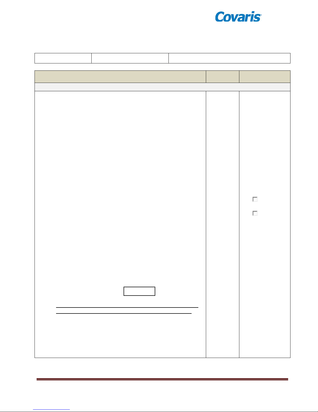
DATE:
INSTRUMENT S/N:
COMPLETED BY:
Power Verification Test
SonoLab Avg. Power
Watts
YES NO
E220 evolution PERFORMANCE QUALIFICIATION (PQ)
(1 of 2)
Action / Requirements Ref. Section Requirement Met?
*The following can be performed duri ng observation of nor m a l sa m pl e
processing or as a st an d-alone experiment.
Denote rack and tube type used for power verification test.
Rack: ___________________________
Tube Type: _______________________
Install desired sample and medium in at least one tube (or simply
fill > 50% with wate r). Load a method commonly used with the
rack and tube types selected. Denote the Peak Incident Power
(PIP) and Duty Factors employed for this Method.
(‘SonoLab Power’
‘Expected Power’
Method Name: ___________________
Peak Incident Power: ______________ Watts
Duty Factor :______________ %
Calculate the ‘Expected Power’ value by the following:
Expected Power = Peak Incident Power X Duty Factor / 100
Expected Power = _________________ Watts
Per standard practice, allow bath water to Degas at least 60
minutes and configure Chiller to desired setting. For most
accurate results, it is recommended that the bath temperature be
between 6 and 17C.
Run the method. Allow treatment to run for ~ 10 se c onds.
Monitor the power reading displayed in SonoLab and record the
average value below. Verify that turbulence is seen in the water
around the tube.
varies from
less than 25%)
Verify the recorded SonoLab average power does not vary more
than 25% from the ‘Expected Power’ value calculated above.
Note: If the Expected Power value is not within specification, repeat
test on a different tube and ensure tube does not contain cracks, pits,
or other damage. If SonoLab power is still not within specification,
contact Covaris Customer Service for support.
E220 evolution User Manual Page 44
Page 45
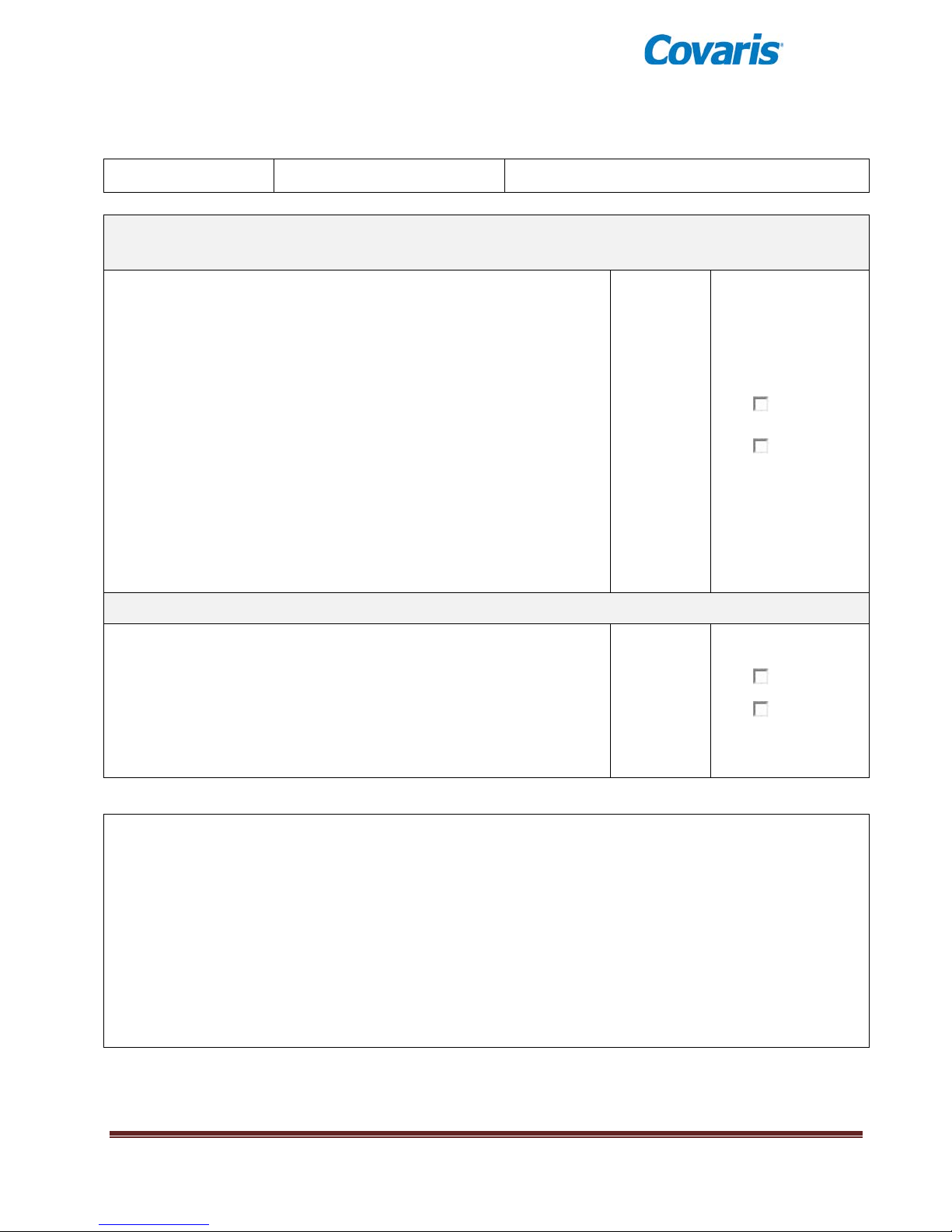
DATE:
INSTRUMENT S/N:
COMPLETED BY:
(Calibrated O2 Meter Required)
Fill Water Bath with fresh water (10-15 on ‘Fill’ side of Water
YES
NO
YES NO
E220 evolution PERFORMANCE QUALIFICIATION (PQ)
(2 of 2)
Degas Performance Test – OPTIONAL
Level Label). Use a calibrated Dissolved Oxygen Meter (i.e.
HACH HQ Series) to measure the baseline oxygen level.
Baseline Dissolved Oxygen Level : ________ PPM (mg/L)
Turn Chiller OFF (or disconnect from instrument).
Install water bath in de vice and turn on Degas Pump using
SonoLab controls.
Allow Pump to run for 1 hour.
Use the 02 Meter to measure the water bath Oxygen content.
Verify the value is LESS THAN 3 .5 PPM
Degas Dissolve d Oxygen Le vel : ________ PPM (mg/L)
User-Defined Test (As Required)
COMMENTS:
E220 evolution User Manual Page 45
Page 46
Appendix B: E Series Site or Transport Preparation
Placement of Equipment
The area required for the instrument (see drawing below) is approximately 23” wide by 30” deep by
19” high (59cm x 76cm x 48cm). Space adjacent to the instrument is required for the laptop
computer, and additional space is required for the recirculating chiller on the bench adjacent to the
instrument, or preferably under the bench.
Leave sufficient space beside the instrument for chiller hoses and behind the instrument for cooling
fan exhaust. Do not block rear panel vents or fans.
The chiller may be placed on the bench adjacent to the instrument or under the bench.
Power Requirements
Provide at least three standard outlets, one for the laptop computer, one for the instrument, and one
for the chiller. A fourth outlet is required if the optional Water Conditioning System (WCS) is
installed.
The instrument draws a maximum of 500 VA. The Covaris E-Series instruments are configured with
a universal power supply. Please note that chillers are generally single-voltage devices and are
rated for the country of use. Verify that the chiller has the correct voltage rating for the installation.
WARNING: To prevent the possibility of electrical shock, always plug the
system into a grounded power source.
Water Requirements
The instrument’s water bath requires about 5.0 liters of either deionized or distilled water, which
should be changed daily. Water is added to the system by manually filling the bath.
If the optional Water Conditioning System (WCS) is used, water need only be changed about once a
month, but must be top ped off periodically to make up for evaporation.
Always run chillers with a 20% solution of a glycol anti-freeze, such as Propylene Glycol, (e.g.
Polyscience PolyCool PG 20 or similar). Operating chillers with pure water risks internal freezing
and permanent damage. Do not operate the chiller with pure antifreeze.
Relocating of the System
When moving the instrument within a laboratory, or between nearby laboratories, please employ the
following guidelines:
• Perform the System Shutdown process described earlier in this manual.
• Close SonoLab and shut down the computer.
• Disconnect power cords and USB cable. Disconnect and drain the chiller.
• Drain the water tank and reinstall in the instrument. Please contact Covaris or your local
representative for assistance.
• Upon arr ival at the ne w loc atio n, fol lo w the Setup and Ins tal lat ion instructions described
earlier in this manual.
E220 evolution User Manual Page 46
Page 47
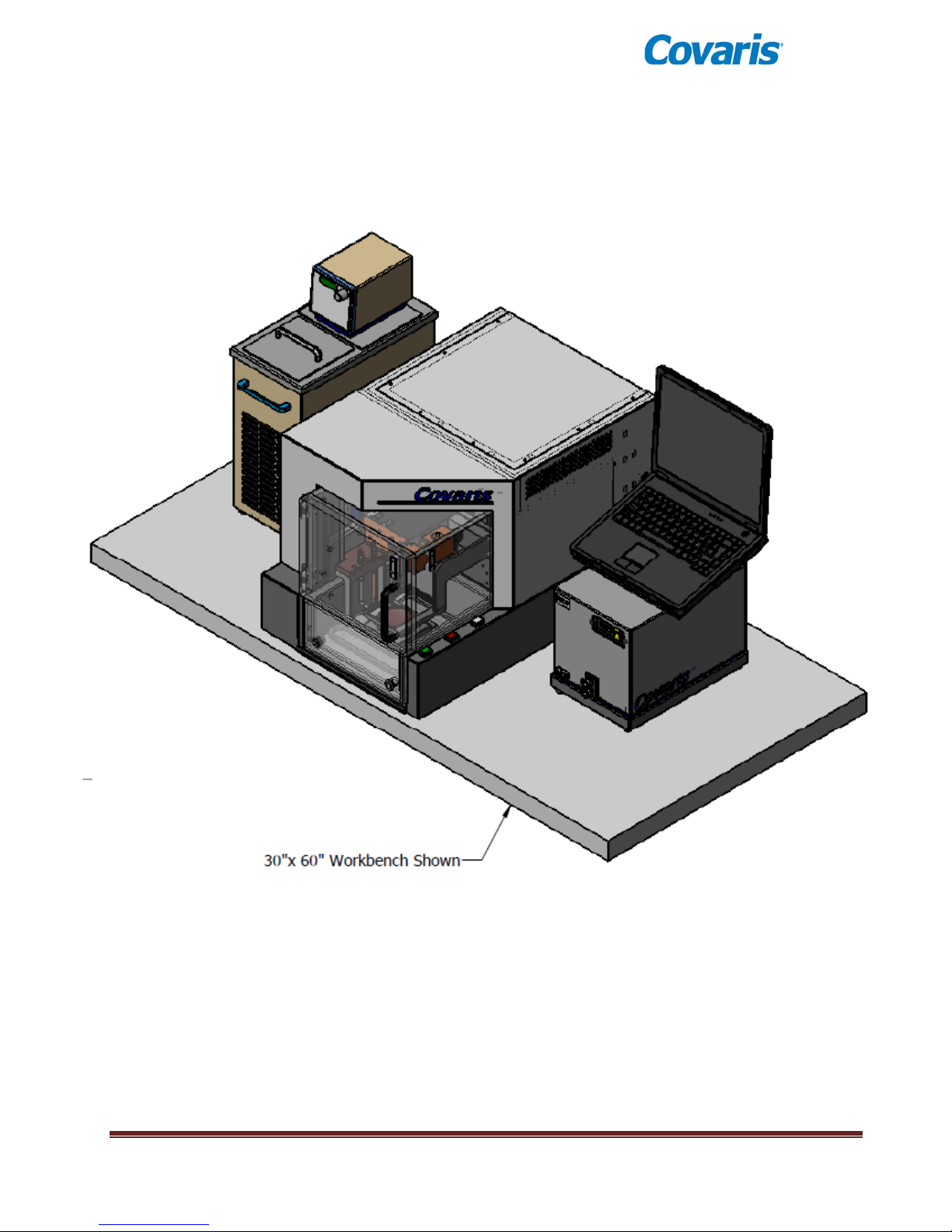
E220 evolution User Manual Page 47
Page 48

Appendix C: Installing SonoLab Software, Firmware and Instrument Drivers
The E220 evolution includes a laptop PC with SonoLab software and device drivers installed. If,
however, it is necessary to replace the computer and re-install SonoLab or device drivers, please refer to
the following instructions.
New copies of SonoLab 7, instrument drivers, user manuals, or protocols may be obtained from the
Covaris website www.covaris.com
. We recommend that you set up a user account at
http://covaris.com/resources/registered-users-login/E-Series/ to gain access to the latest updates and
software versions.
Please also contact Covaris technical support or your local representative for downloads of software,
drivers, manuals, or protocols.
Installing SonoLab
1. Begin with the computer ON and Windows running.
2. Download the appropriate SonoLab version from Covaris and extract the installer files to the
desktop, or if available, load the SonoLab Install CD onto the Laptop’s CD-Drive.
3. Auto-start the CD, or right-click “setup.exe” in the SonoLab 7 folder to launch the software setup
process.
4. If Windows asks if this is a trusted application, or if you wish to make changes, answer Yes. Follow
the instructions for installation. When installation is complete, close the installer. A “Sonolab 7”
shortcut should appear on the computer desktop.
5. With the instrument powered ON, double click on the Sonolab 7 shortcut. SonoLab will open its
splash screen, as described in Section 3 of this manual.
Installing Well Plates (210050)
1. To install the standard set of plate definitions, open the installer and double-click the Setup
application. The Windows installer wizard performs the installation. Click the ‘Close’ button when
the ‘Successfully Installed’ message displays.
Firmware Update
If you have updated your SonoLab version, you may need to update your instrument Firmware
1. A dialog box may pop up to alert you that the firmware of the instrument is out of date. Click OK to
close this box.
2. To update instrument firmware, User Authentication must be enabled, and a SonoLab Administrator-
level user must be logged into SonoLab 7 to allow firmware update. See Section 4 for details on
User Authentication and Administrator log in.
3. Click on the Maintenance Tab and click on the Firmware Update Tab.
4. With the instrument power ON and connected to SonoLab, click on the Start Updating Firmware
button. Several dialog boxes will appear describing update progress. Please allow this process
(approximately 15 minutes) to complete. Do not interrupt the process or turn instrument power off
while the download is taking place.
5. When complete, you may simply return to normal operation. The About tab will display the new
software and firmware versions.
6. To disable User Authentication (if desired), go to Setup and User Authentication, and un-check the
Enable box. The Administrator will be logged out and User Authentication disabled.
7. SonoLab 7 and the instrument are now ready to use.
E220 evolution User Manual Page 48
Page 49
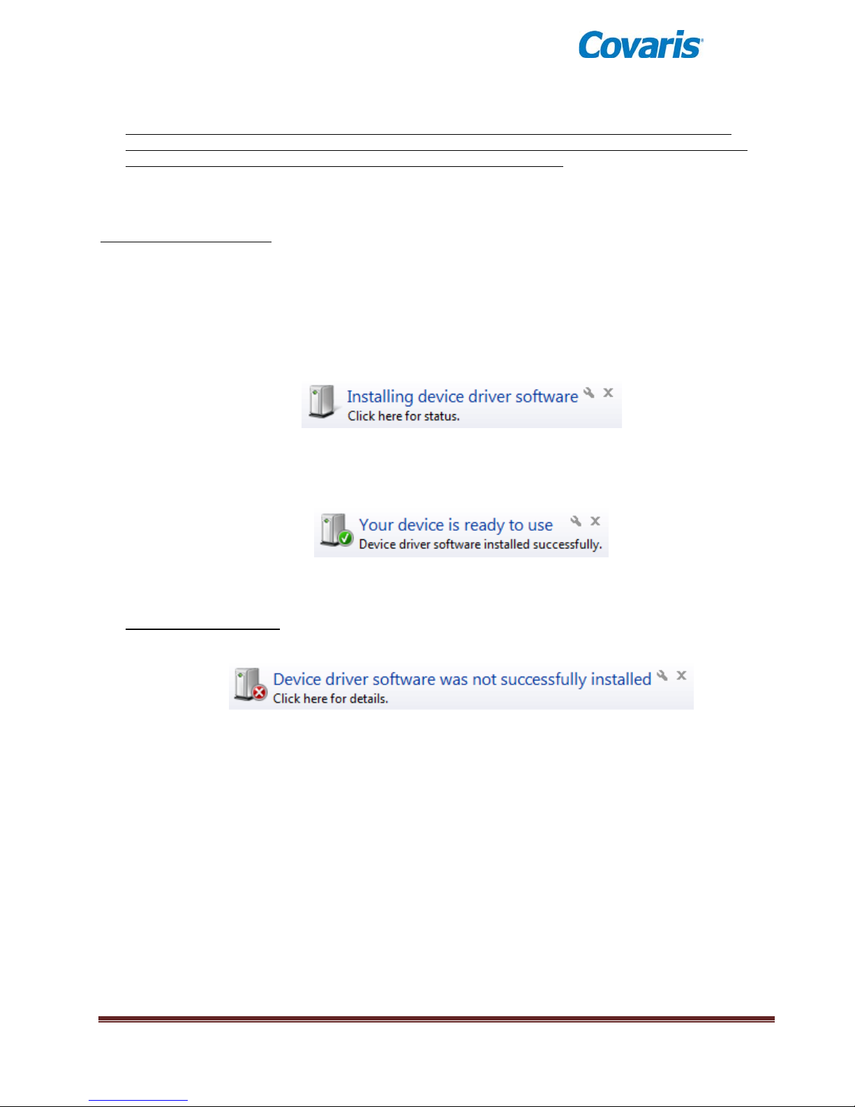
Install Windows Instrument Driver
When an instrument (with power ON) is connected by USB (Universal Serial Bus) for the first time,
Windows will identify the instrument by its Vendor and Product ID numbers and install specific device
drivers (software files required for communications with a USB device).
Windows will attempt to install these drivers in the following order:
Automatic driver installation:
If any E220e has ever been connected to the computer, then a copy of the appropriate drivers will be
available to Windows locally, and Windows will automatically install these.
If Windows does not find a local copy of the necessary drivers, it will automatically search Windows
Update (assuming internet access is available via wireless link or Ethernet cable and Windows is
configured for automatic updates).
In either case, upon locating them, Windows will automatically install the drivers and pop up the
following message onto its desktop:
Drivers for several devices within the instrument will be installed sequentially. This may take several
minutes. If you click on the pop-up message, the status of these installations may be viewed.
Please allow all of these drivers to install and for Windows to confirm successful installation of all
drivers with the following message:
Drivers are now installed and SonoLab 7 will automatically connect with the instrument once started.
Manual driver installation:
If the automatic installation fails to occur, Windows will post the following message:
If restoring internet connection or automatic Windows Update fails to start the automated installation
process, then the following manual process will be required.
Click on the Windows Start button. Either via Control Panel, or by right-clicking on Computer and
choosing Properties, locate Device Manager. Click on this link to open the Device Manager
window. In the list of devices, locate Other devices and entries for RF Controller Board:
E220 evolution User Manual Page 49
Page 50
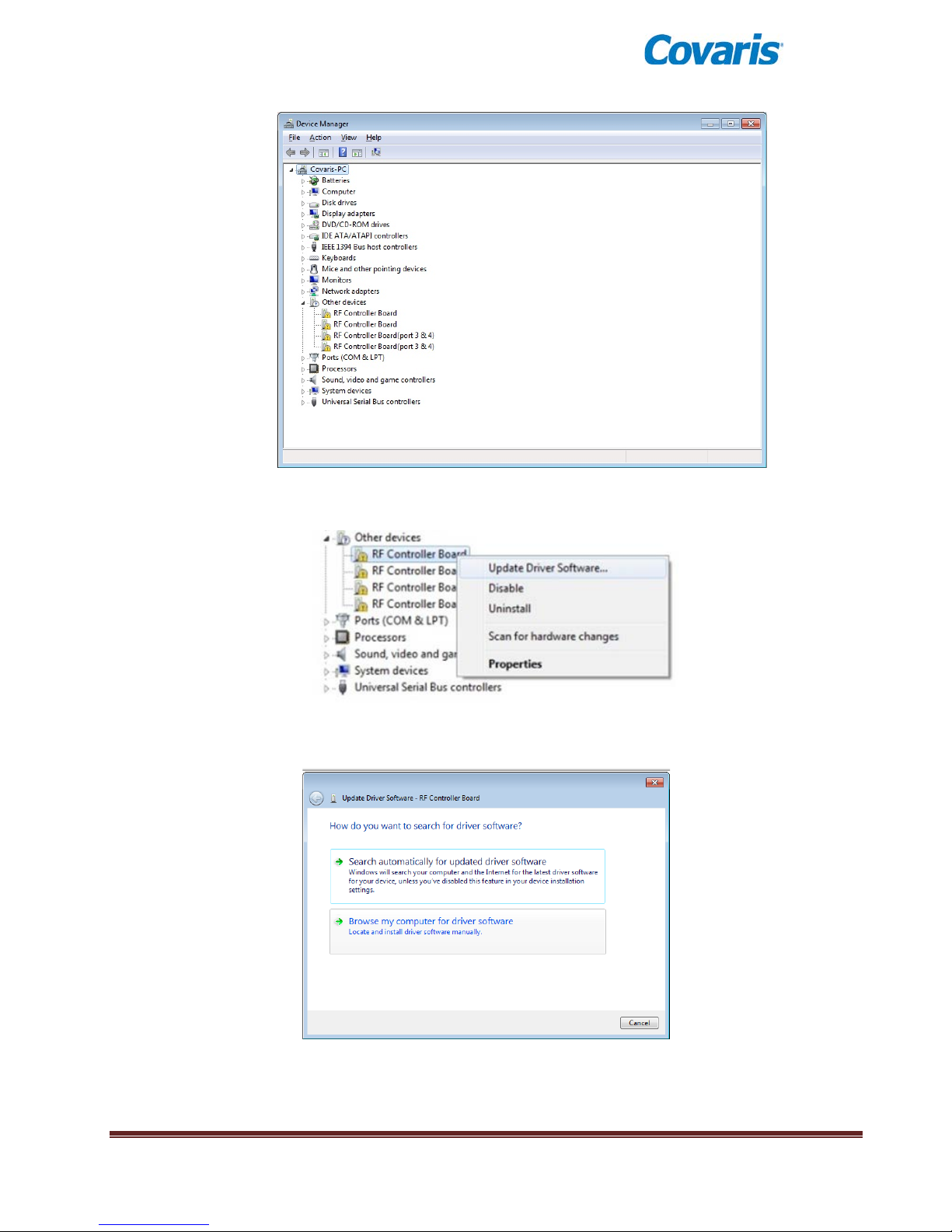
Under Other devices, right click first device RF Controller Board and select Update Driver
Software:
When the driver software update dialog opens, select the option to Browse my computer for driver
software:
E220 evolution User Manual Page 50
Page 51
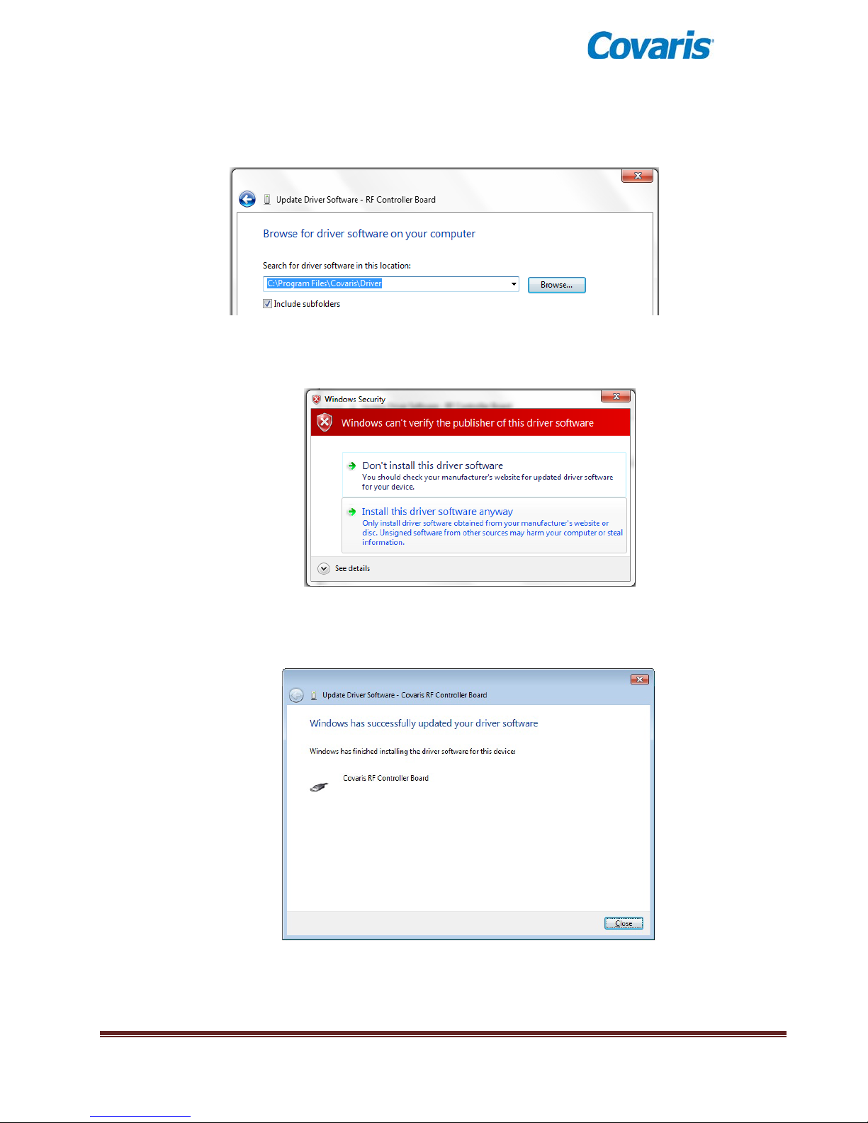
Point the file open dialog to “C:\Program Files\Covaris\Driver” and verify that “Include subfolders” is
checked:
Click next. You may be notified that “Windows can’t verify the publisher of this driver software”. Click
on “Install the driver software anyway”:
Windows will install the driver and post the following dialog box with a message, “Windows has
successfully updated your driv er sof twar e” .
Click the Close button. The Device Manager screen will refresh.
E220 evolution User Manual Page 51
Page 52
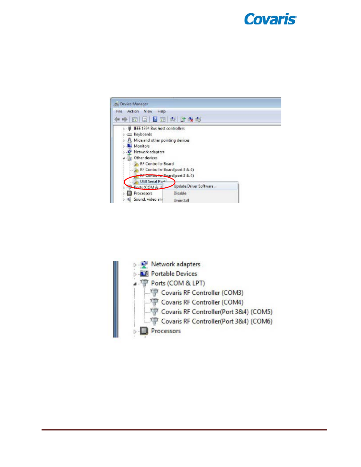
Return to Other devices. Note that there is now a ‘USB Serial Port’ liste d under the thr ee ‘RF
Controller’ lines. Right-click on the ‘USB Serial Port’ and select ‘Update Driver Software…’, as
shown in the image below. Repeat the installation steps shown above.
Return to Other devices and repeat this process in order (top to bottom), for the 3 remaining
entries, until all Covaris device entries have been assigned a COM number under Ports (COM &
LPT). The ‘Device Manage’ window should now show:
Note that the ‘COM’ numbers will vary from computer to computer, but should occupy four
consecutive ports.
E220 evolution User Manual Page 52
Page 53
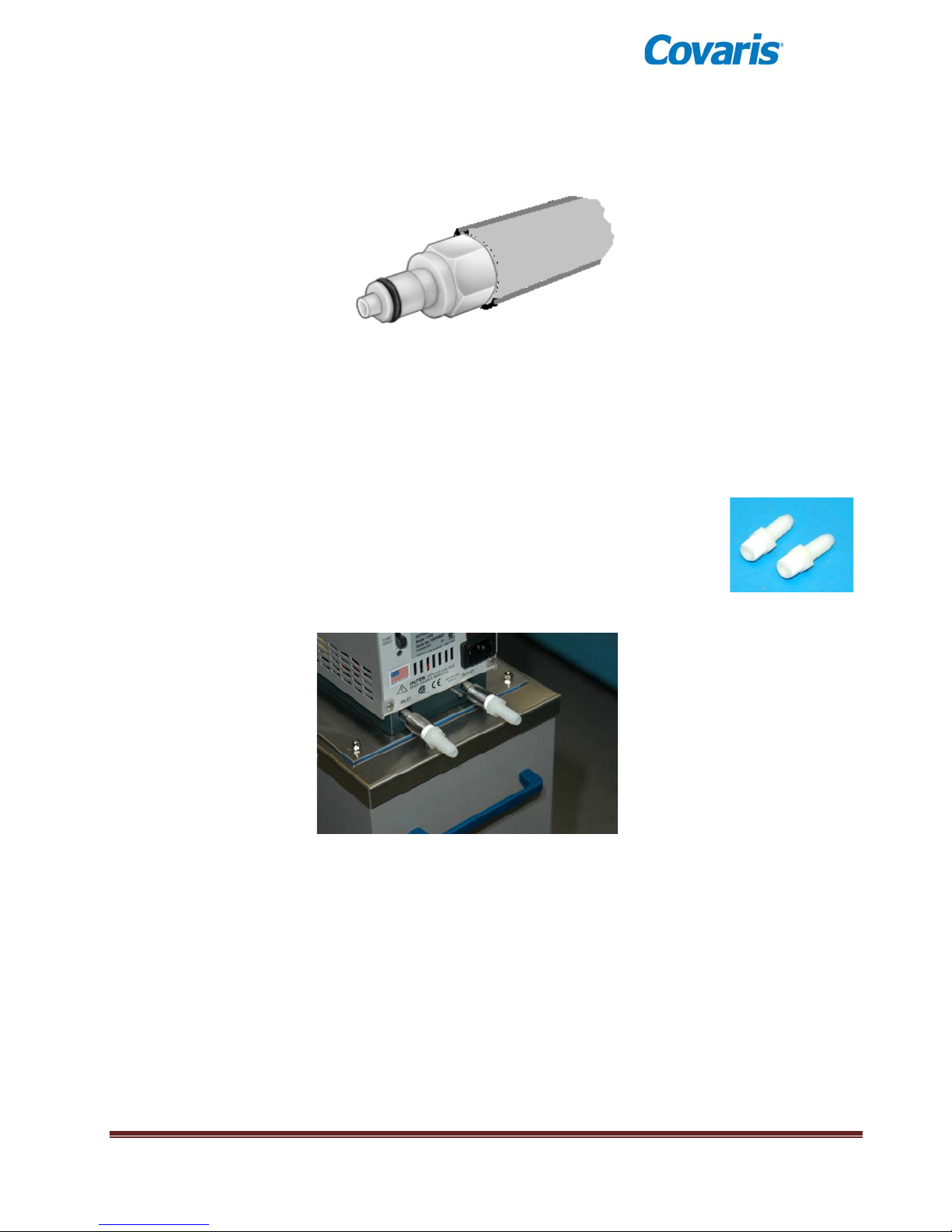
Appendix D: Recirculating Chiller
The instrument is supplied with two insulated hoses for chiller loop hook-up. One end of each hose is
equipped with a
Quick-Disconnect Coupling Plug, ¼ inch, for 3/8 inch interior diameter tube ID.
This end of each hose is designed to connect to the chiller connections on the left side of the instrument.
The other end is left open to allow connection to a variety of chillers. These connections are typically made
with barbed fittings equipped with a barbed adapter able to connect to the chiller.
Covaris typically supplies a chiller with each instrument, normally with quick-connect fittings pre-installed.
Alternatively, u sers may purchase a chiller separately. It is recommended that the chiller have a capacity of
at least 250 Watts at a set point of 5°C, and able to deliver a minimum pump pressure of at least 14.5 psi
(1.0 bar).
For convenience, Covaris provides an assortment of barbed fittings for use with non-
®
Covaris chillers. If utilizing these, apply Teflon
tape to the threads of the barbed
adapters as shown at right, and screw these adapters into the INLET and OUTLET
ports of the chiller (typically located on the rear panel of the chiller). Use a wrench to
tighten the fittings, but to not over-tighten as this may damage the threads. An example
is shown in the image below:
Remove the Quick-connect couplings from one end of each hose and connect this end of the hoses to the
fittings. For added security, tighten the hose clamps as shown below:
E220 evolution User Manual Page 53
Barbed fittings insta ll e d on a chiller
Page 54
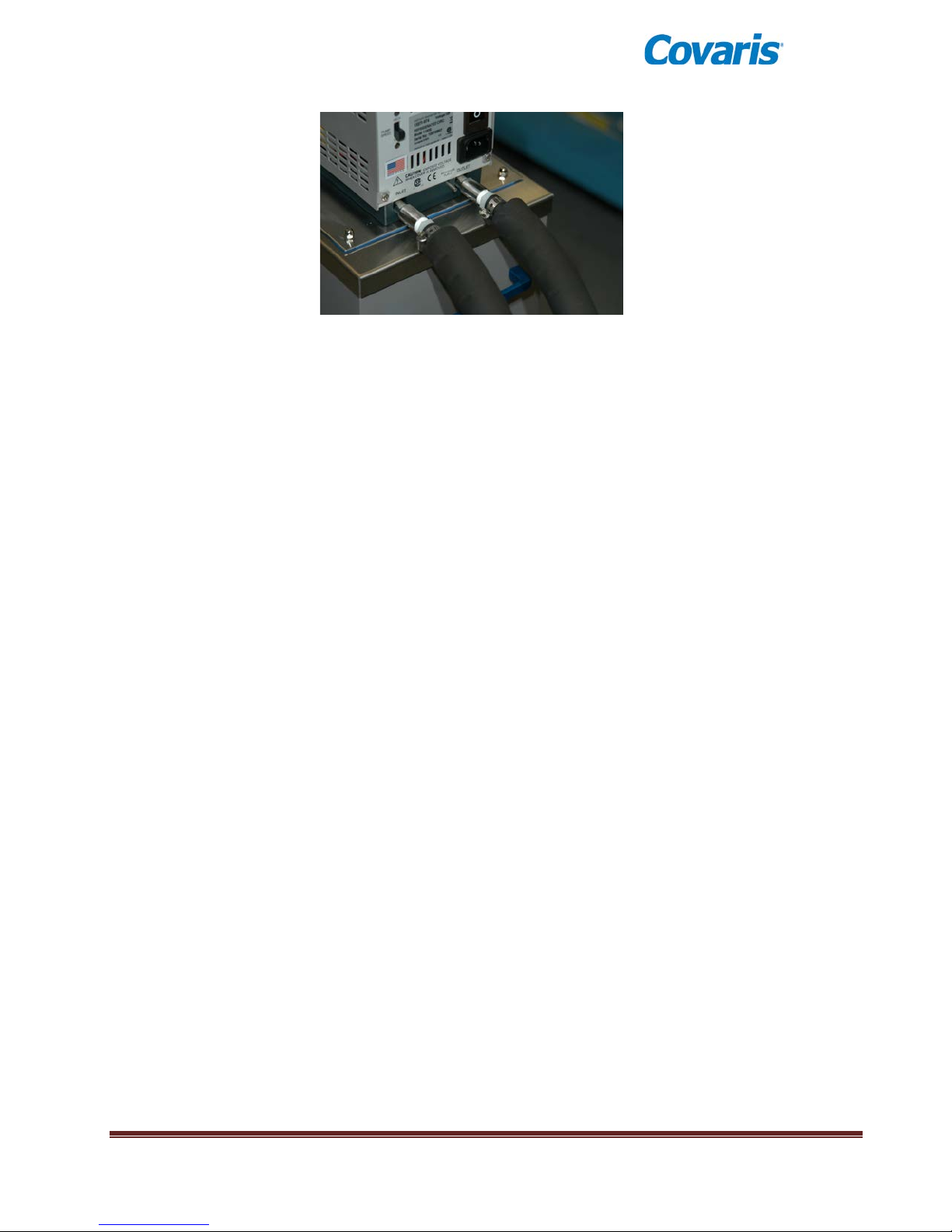
Hoses assembled to barbed fittings
Connect the other ends of the hoses (the ends with the quick-connect fittings pre-installed) to the ports on
the left side of the instrument. These connections are bi-directional. There is no specific INLET or OUTLET.
Follow the instructions provided in the chiller user manual to fill the unit with a water-glycol solution. Covaris
recommends a 20% solution of propylene gl ycol, such as Polyscience PolyCool PG 20 in the chiller, to
prevent freezing in the heat exchanger. Do not use pure antifreeze, as this thickens when cold causing
chiller flow faults.
The Covaris CH-03 Chiller (PolyScience MM7) has a reservoir capacity of 2.7 liters. Add .5 liters of glycol to
the empty reservoir and fill with water to yield approximately a 20% mix.
The Covaris CH-04 Chiller (PolyScience AD-07) has a reservoir capacity of 7 liters. Add about 1.5 liters of
glycol to the empty reservoir, then fill to within an inch of the top for approximately a 20% mix.
Please also follow the chiller manufacturer’s instructions regarding power connections, changing the chiller
fluid, draining and/or cleaning the system, and any air filter maintenance.
To test the setup, turn the chiller ON, program the set point to a low (but non-freezing) temperature, such as
4°C, and verify that the chiller temperature begins to drop. As the chiller temperature approaches the cold
set point, verify that the stainless steel chiller coils in the instrument are cold.
Fill the instrument’s bath with DI water, start SonoLab, and allow the chiller and degas pump to operate for at
least 60 minutes. Verify that the Degas status has turned green, and that the bath temperature has reached
(or is approaching) a few degrees above the chiller’s set point.
The instrument and chiller system is ready to use.
E220 evolution User Manual Page 54
Page 55

APPENDIX E: Humidity and Water Management in Covaris E and LE Systems
Covaris E and LE Systems employ a six-liter tank of distilled or deionized water located inside the instrument
housing. For the system to operate correctly, the water must be filled to an appropriate level (dependent
upon the protocol being run), must be clean, free of algae growth, and degassed to retard bubble formation
in the acoustic field outside of the sample vessel. Additionally, bath temperature should be controlled by an
external chiller connected to the system’s chiller loop. Managing this water and associated humidity is
important for the correct operation and reliability of your Covaris system. The following suggestions will help:
• When the system is powered on, the interior is vented by fans located in the rear panel to maintain
an appropriate air temperature and humidity within the instrument enclosure. It is recommended,
when the acoustic tank is full, that the instrument be left with power on, so that these fans run and
retard water condensation on interior surfaces. If it is not practical or desirable to leave these fans
running when the instrument is not in use, please leave the front access door ajar so that interior air
may exchange with ambient air. The risk of condensate forming within the instrument is increased
when operating with a Water Conditioning System (WCS), because the WCS will add a small
amount of heat to the bath water.
• To maintain a clean system, Covaris recommends that the bath water be changed daily and that
once each month, the tank be disconnected from the WCS (if applicable) and filled with a 10%
solution of bleach (e.g. Clorox). Run this solution through the degas system for a few minutes and
change back to pure water. The bleach will kill algae growth that may have begun inside hoses or
along the inner wall of the tank.
• Employing the optional WCS with an E or LE System precludes the need for a daily change of bath
water. It is, however, important that water which evaporates each day be made up with fresh
distilled or deionized water. It is also important that a monthly bleaching protocol continue to be
followed, as the WCS will retard but cannot completely prevent algae from taking hold in hoses and
interior tank surfaces. Detach the WCS water flow from system when bleaching.
• When the system is being employed with a chiller set to a low temperature, you may notice
condensate water forming on the black manifold block, on hoses leading to the degas pump, and
around the fittings and chassis of the WCS (if employed). Particularly in summer, when relative
humidity is higher, condensate may drip onto interior surfaces and small amounts may leak onto the
laboratory bench. This condensation is expected and no harm is being done to the system. Excess
condensate dripping onto a laboratory bench may be captured by placing an absorbent pad (e.g.
VWR 82020-845) beneath the system and/or WCS.
• If operating the acoustic bath at temperatures at or near 4°C, it is important to realize that
temperatures in the chiller will be approaching zero degrees. To retard freezing within the chiller, it
is recommended that a 20% solution of ethylene glycol be employed in the chiller water. Most chiller
and laboratory suppliers carry ethylene glycol for this purpose. Do not employ automotive antifreeze, and do not put glycol in the E or LE acoustic bath water.
• If the instrument is going to be idle for more than 2 weeks, it may be beneficial to turn all
components off to prevent any damage to the instrument. Please follow the recommended
sequence:
1. Turn off chiller
2. Move instrument to service position
3. Turn WCS off and disconnect hoses
4. Empty the water tank
5. Replace the water tank and move instrument to load position
6. Purge the degas pump by turning on for 10 seconds. Purge the WCS lines by connecting the
hoses and powering on WCS until flow subsides
E220 evolution User Manual Page 55
Page 56

7. Turn the WCS off and disconnect hoses. Raise instrument to service position.
8. Empty the water tank and dry
9. Gently dry transducer and surfaces of instrument.
E220 evolution User Manual Page 56
 Loading...