

COVANA Evolution Series, Evolution GHSC Installation Manual

1 INSTALLATION MANUAL
Revision 1
2017/05/29
Revision 2
2017/11/10

2 TABLE OF CONTENTS INSTALLATION MANUAL
TABLE OF CONTENTS
TABLE OF CONTENTS ............................................................................................................................................. 2
SAFETY ...................................................................................................................................................................... 4
Safety information ................................................................................................................................................... 4
LABELING ................................................................................................................................................................. 7
GLOSSARY ..............................................................................................................................................................10
HARDWARE IDENTIFICATION TABLE .................................................................................................................14
INSTALLATION PREPARATION ............................................................................................................................16
Location considerations ........................................................................................................................................16
Foundation preparation.........................................................................................................................................18
INSTALLATION .......................................................................................................................................................18
Uncrating ..............................................................................................................................................................18
Assembly ..............................................................................................................................................................22
Lifting mechanism assembly ................................................................................................................................27
Testing the Evolution cover ..................................................................................................................................35
Applying the wiper bracket....................................................................................................................................36
Seal application ....................................................................................................................................................37
Non-permanent mounting plates installation ........................................................................................................39
ELECTRICAL HOOK-UP .........................................................................................................................................40
Avoiding the risk of electrocution ..........................................................................................................................40
Grounding and power supply connection .............................................................................................................41
TECHNICAL SPECIFICATIONS ..............................................................................................................................42
Side elevation dimensions ....................................................................................................................................42
Frame dimensions and foot print ..........................................................................................................................43
Electrical specifications.........................................................................................................................................45
Operating limitations .............................................................................................................................................45
General specifications ..........................................................................................................................................45
LIMIT SWITCH ADJUSTMENT ...............................................................................................................................46
TROUBLESHOOTING .............................................................................................................................................47
APPENDIX ...............................................................................................................................................................49
Wiring diagram (North America) – 60 Hz, 120 VAC Operator ..............................................................................50
Wiring diagram (Europe) – 50 Hz, 220 VAC Operator .........................................................................................51

INSTALLATION MANUAL TABLE OF CONTENTS 3
INSTALLATION CHECKLIST (Customer copy) ....................................................................................................52
INSTALLATION CHECKLIST (Installer copy) .......................................................................................................55
4 INSTALLATION MANUAL
SAFETY
IMPORTANT SAFETY INSTRUCTIONS
SAVE THESE SAFETY INSTRUCTIONS AND
REVIEW THEM REGULARLY.
Safety information
The Covana cover was designed, tested and certified
to be installed over a residential hot tub and under
important installation instructions issued by Covana.
Any other type of usage will void the warranty and
product certification.
The extra load maximum weight provided in the
specification section of this manual is a provision for
environmental outcomes, such as a small amount of
leftover snow or damp leaves that temporarily
accumulate on the cover and evenly distributed on the
surface of the cover.
The Covana cover was not designed to support any
additional load or people walking or standing on its lid.
Failure to observe this instruction will void the cover’s
warranty and nullify its certification.
The power safety cover meets ASTM F1346-91
requirements.
DANGER
To reduce the risk of injury, do not allow children
to use this product unless they are supervised at
all times.
Failure to follow all instructions may result in
injury or even death.
Do not allow people to climb or walk on the
cover.
Do not allow children to have access to the
Covana cover without supervision.
Never operate the Covana cover until all people
and objects are out of the spa.
WARNING
Be sure to keep the key switch and the key out
of the reach of children.
Do not put any type of fabric or plastic sheet,
such as a tarpaulin, on the Covana cover. This
could overheat the cover and result in
deformation or delamination of the cover.
Inspect the cover periodically. It should raise
smoothly and evenly. Contact your Covana
dealer if any unusual mechanical sound is heard
during use.
Never use any type of pressure washer or buffer
to clean any surface of the Covana cover. This
could result in premature wear or damage.
Use a pressure washer to clean any component
of the Covana cover.
DO
Remove the control key after operating the
Covana cover. Store the key in a secure location
when not in use. Users must bring the control key
in the hot tube with them to prevent unauthorized
operation of the cover.
Never leave the key in the key switch.
Check the cover frequently for signs of
deterioration.
Have any repairs, adjustments or mechanical
work performed by your certified Covana dealer
as soon as possible when you notice a
malfunction.
Close the cover when it is not in use or if the
swim spa is not being monitored.
DO NOT
Operate the unit before all mechanical and
electrical connections have been made.
Step on or stack anything on the Covana control
box.
Operate the Covana cover while somebody is in
the hot tube.
Climb, walk or stand on the Covana cover at any
time.
Leave the Covana cover open for more than 12
hours. This could cause the cover to warp.
Converge or directly reflect sunlight on the cover.
This could cause permanent damage.

INSTALLATION MANUAL SAFETY 5
Wash the cover with harsh chemicals or
cleaners.
Use an extension cord to connect the Covana
cover to its power source. The cord may not be
properly grounded and the connection is a shock
hazard. An extension cord may cause a voltage
drop, which would cause the motor to overheat.
CAUTION
Be sure to follow all instructions in this manual
and use only accessories and tools approved by
Covana.
Do not roll the Covana cover onto its side or slide
it on its side. This will damage the siding.
After removing a part, always place it in a safe
place on a clean and level surface to ensure
proper functionality.
All four jacks of the Covana cover must be
properly anchored to the foundation using the
anchoring holes located at the foot of each jack.
The optional non-permanent mounting plates
can be used when anchoring is not possible, but
under strict condition. See ‘’Non-permanent
mounting plates installation” section for details.
This product mainly contains steel, plastic,
copper (Cu) and die-cast aluminum (Al). The
gearbox contains oil and other materials. Please
recycle them properly.
Both the up and down limit switches are pre-
adjusted at the factory. The down-limit switch
should never be re-adjusted. The up-limit switch
should be re-adjusted only to reduce the
maximum height of the cover to avoid possible
contact with its surroundings. Please refer to the
Limit Switch Adjustment section in this manual
before making any adjustments. An improper
adjustment can result in damage to the drive
system and/or cover.
Avoiding the risk of electrocution
ELECTRICAL DANGER
Failure to comply with these instructions may
result in death by electrocution or serious injury.
Disconnect or turn off and secure all power
supplies before starting any intervention on the
Covana cover.
Always have a licensed electrical contractor
perform any electrical maintenance or repairs on
the Covana cover. The wiring must comply with
all applicable local electrical codes and
regulations.
The Covana operator must be connected to a
circuit that is protected by a Class A dedicated
ground-fault circuit-interrupter (GFCI) that
complies with all applicable local electrical codes
and regulations.
Install the Covana cover in such a way that
drainage directs water away from the electrical
components and base mechanical components.
Do not connect any auxiliary components to the
electrical system of the Covana cover unless
they have been approved by Covana.
Replace electrical components with original
components provided or approved by Covana.
Ask your dealer for replacement parts.
To reduce the risk of electrical shock, replace a
damaged cord immediately. Failure to do so may
result in death or serious personal injury due to
electrocution.
Do not bury the power cords. A buried power
cord may result in death, or serious personal
injury due to electrocution if direct burial-type
cable is not used, or if improper digging occurs.

6 SAFETY INSTALLATION MANUAL
ELECTRICAL WARNING
To reduce the risk of electric shock, the green-
colored terminal or the terminal marked “g,” “gr,”
“ground,” “grounding” or with a ⏚ symbol that is
located inside the supply terminal box or
compartment must be connected to the
grounding means provided in the electric supply
service panel with a continuous copper wire
equivalent in size to the circuit conductors
supplying the equipment.
Two lugs marked “bonding lugs” are provided on
the external surface or on the inside of the supply
terminal box or compartment. To reduce the risk
of electric shock, connect the local common
bonding grid in the area of the Covana cover.
Use terminals with an insulated or bare copper
conductor not smaller than No. 6 AWG (4.11
mm).
To reduce the risk of electrical shock, replace a
damaged cord immediately. Failure to do so may
result in death or serious personal injury due to
electrocution.
All field-installed metal components, such as
rails, ladders, drains or other similar hardware,
within 10 ft. (3 m) of the hot tub must be bonded
to the equipment grounding bus with copper
conductors not smaller than No. 6 AWG (4.11
mm). (NEC art. 680.)
WARNING REGARDING DRUG OR
ALCOHOL USE
The use of drugs or alcohol while operating the
Covana cover is strictly prohibited. The
impairment of judgement, vision or hearing might
affect the security of other people or result in
death.
WARNING REGARDING
MODIFICATIONS TO THE COVANA
COVER
Any modifications to the Covana cover, such as
mechanical, electrical or aesthetic ones, may
cause the cover to operate in an unwanted or
dangerous way. Furthermore, these
modifications are not permitted and might void
the warranty and certification.
The Covana cover has been designed, tested
and certified for the only purpose of covering and
securing a spa. Any installation that differs partly
or entirely from this purpose will void the
warranty and certification.
INSTALLATION MANUAL 7
LABELING
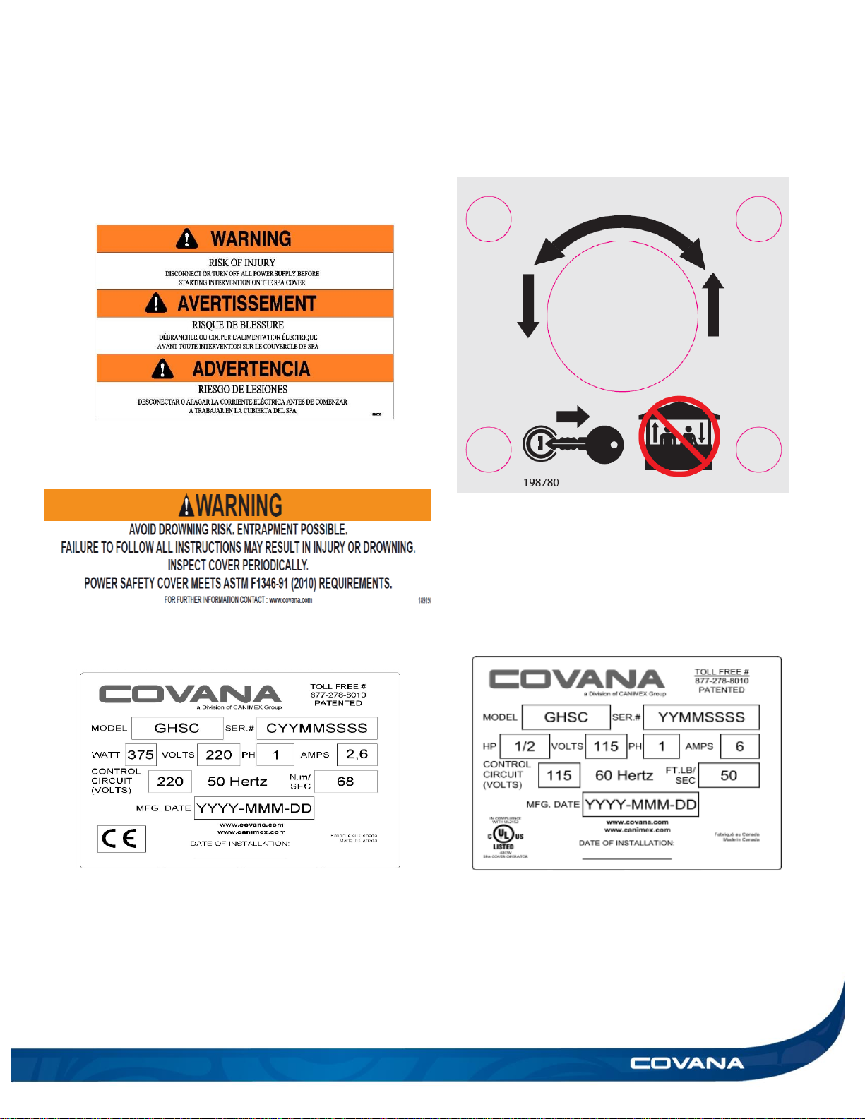
Risk of electrocution warning, located on
the operator.
Drowning risk warning, located on the
inside of the Covana cover.
Specification sticker, located on the operator
(European model) Note: This sticker
provides the serial number.
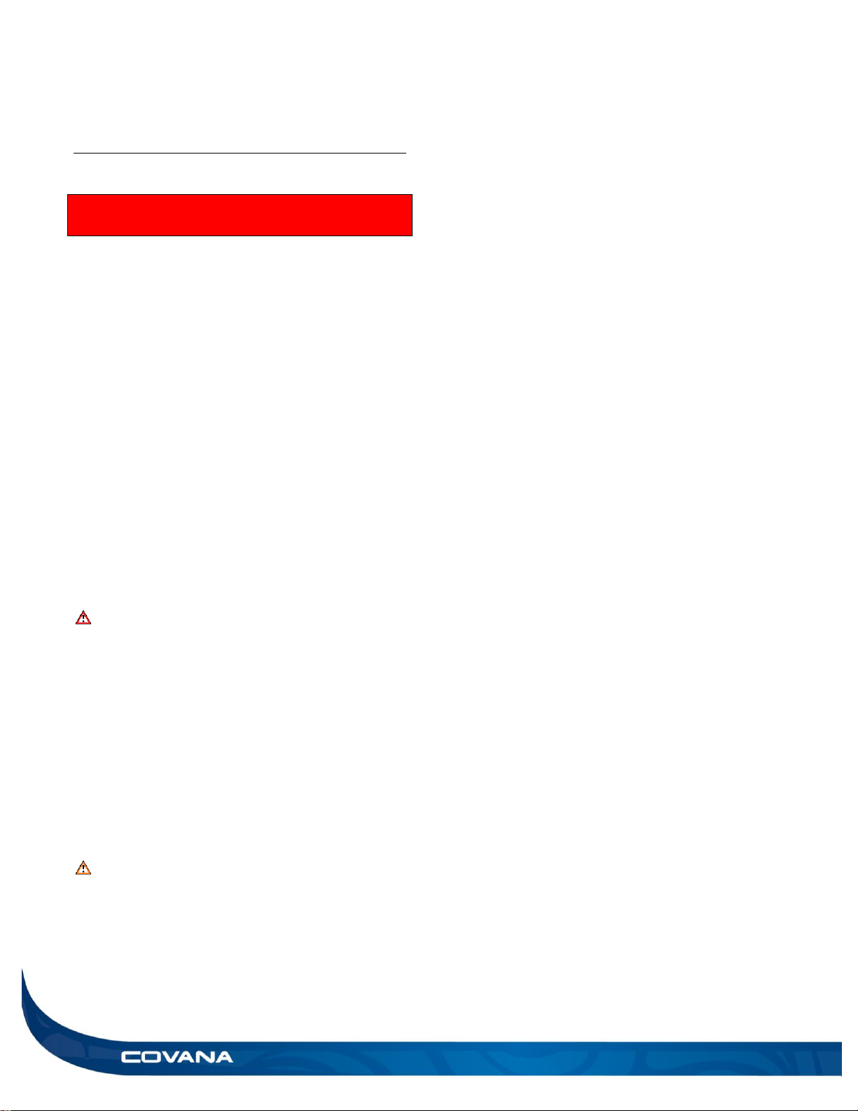
Key operating diagram, located on the key
switch.
Specification sticker, located on the
operator.
(North American model) Note: This sticker
provides the serial number.
8 LABELING INSTALLATION MANUAL
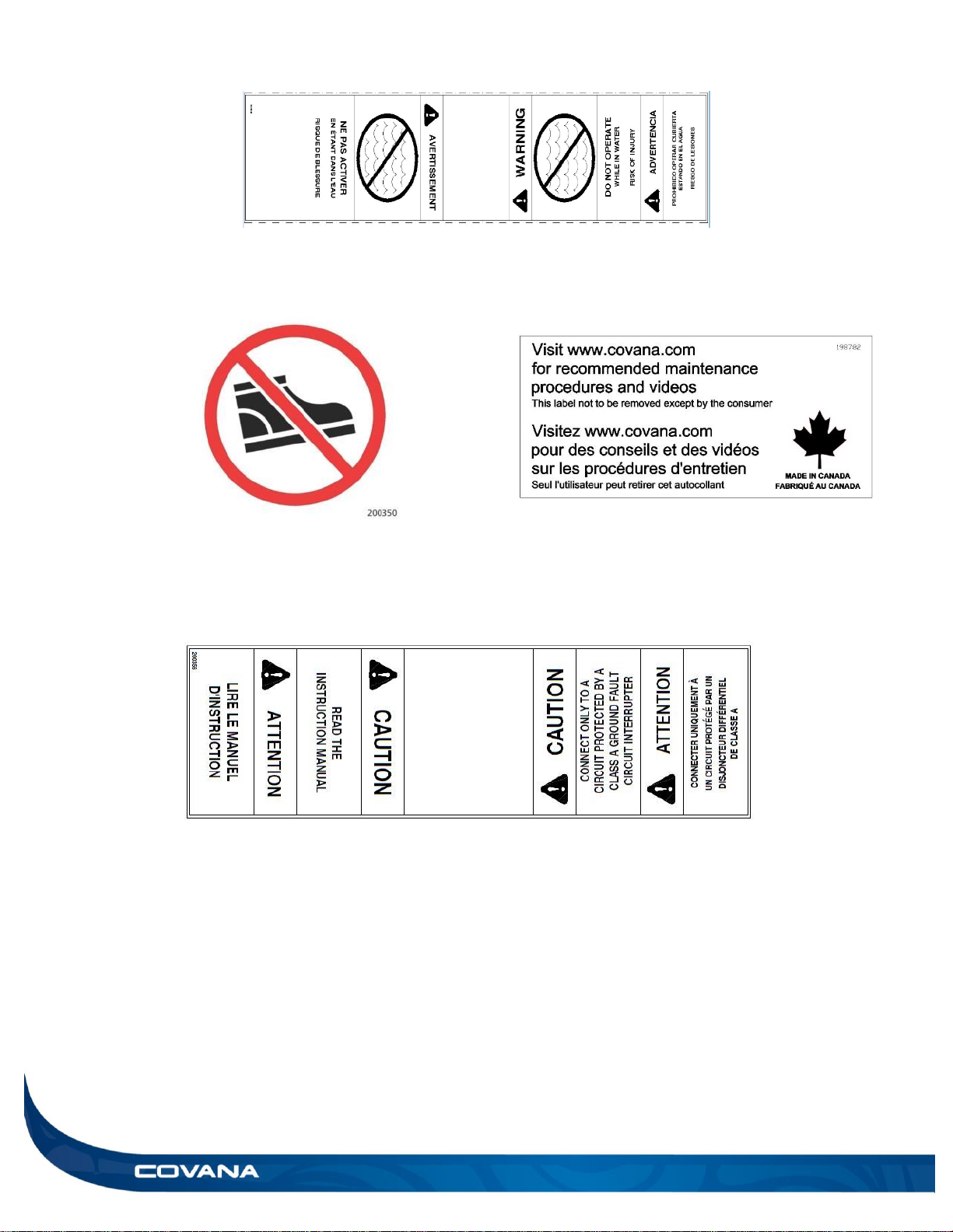
Sticker located on the key switch cable.
Do not step symbol, located on top of the operator. Sticker located on the outer shell.
Electrical information, located on the key switch cable.
INSTALLATION MANUAL LABELING 9
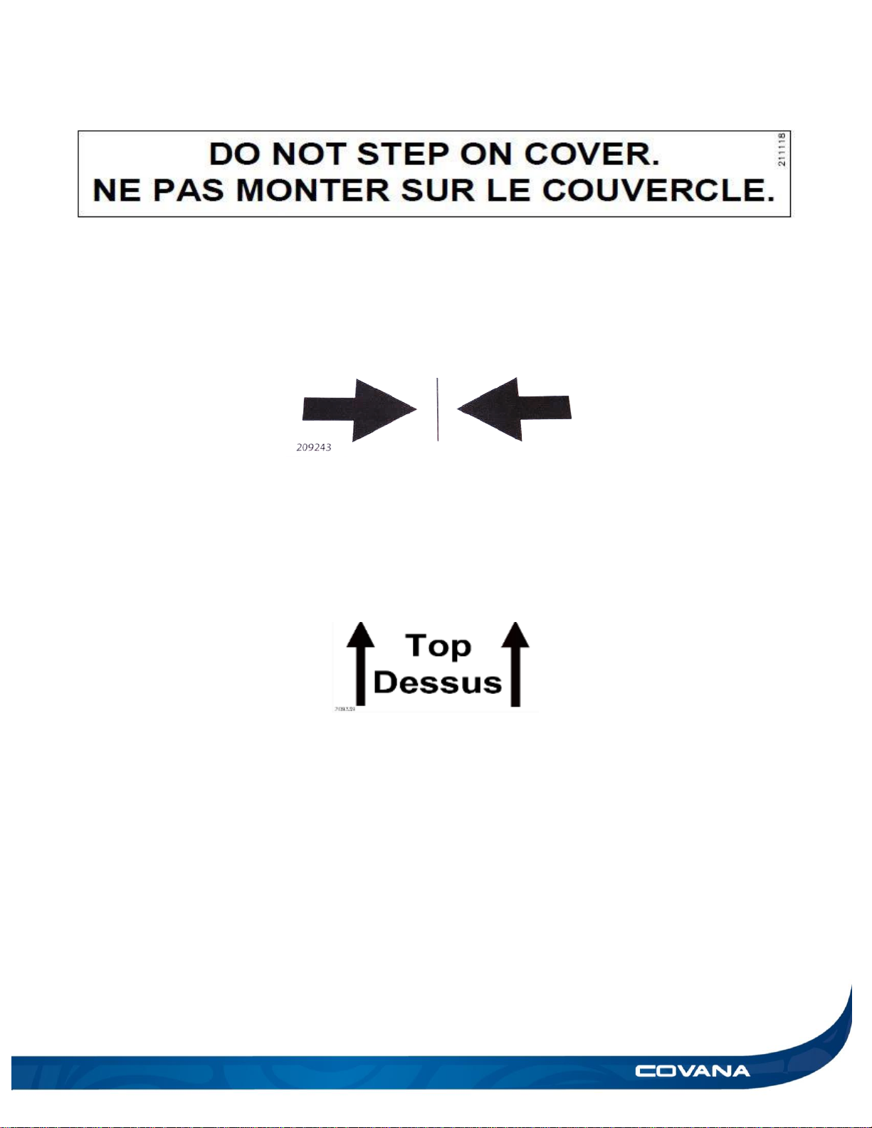
Do not step on cover sticker located of the end C-channels of the Evolution cover.
Center sticker located on the center of the 94 9/16 in. (240 cm) C-channel.
Top sticker, located on the interior of the I-beams and escape hatch opening to indicate
orientation.
10 GLOSSARY INSTALLATION MANUAL
GLOSSARY
Part
Figure
Function
All-weather seal
The all-weather seal prevents water from leaking between the
sleeves when the Covana cover is fully closed. Failure to install this
part may result in water infiltration in between the sleeves and
damage to the mechanism.
Binding block
The binding block is used during installation to tighten the I-beams
with the panels. It allows the use of straps without damaging the
components of the Covana.
C channel
The C-channel is the outer frame of the cover. The panels are
installed between the C-channels
Contour seal
The contour seal ensures uniform contact between the inner shell
and the hot tub. It prevents excessive water and other contaminants
from entering the hot tub. It also reduces heat loss.
Contour seal
installation clip
Contour seal installation clips are used during the installation
process to ensure the seal is installed properly.
Contour seal
connector
The seal connector is used to link both ends of the seal. It ensures
a strong and effective joint.
Figure 6
Figure 4
Figure 5
Figure 1
Figure 2
Figure 3
INSTALLATION MANUAL GLOSSARY 11
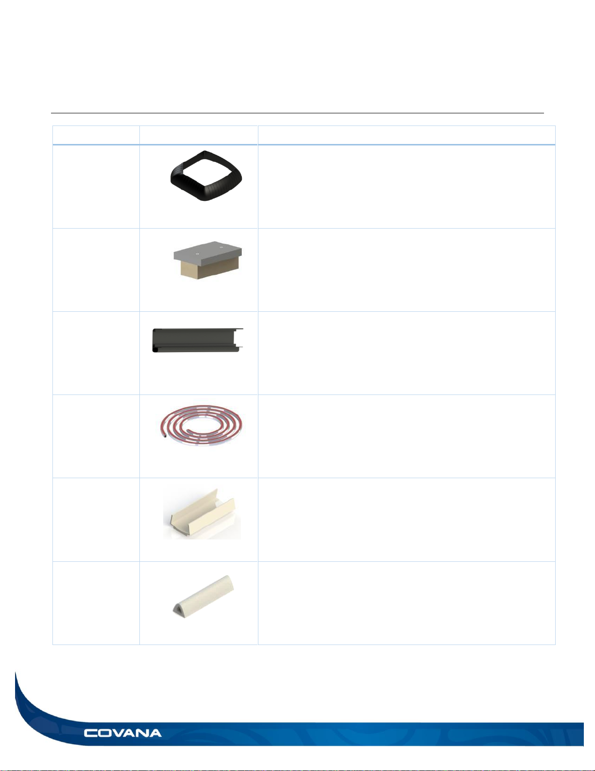
Corner bracket
The corner bracket is the piece that links the cover to the sleeves.
There is one in each corner of the Covana cover to ensure proper
weight distribution.
Corner bracket
The corner brackets links the C-channels on the side to the ones in
front and back. It holds in place with 3 screws per C-channel. Never
use a power tool to screw hardware, as they might break.
Drive shaft
The drive shaft transmits the power between the motor-side and
non-motor-side jack assemblies.
Escape hatch
The escape hatch is a removable panel part of the cover. In case of
entrapment, the escape hatch is removable from the inside by
turning the locking mechanism.
Hammer block
The hammer block is a piece of plastic or wood used during the
installation to hit on the panels without damage. To use the hammer
block, insert the opening of the block on the foam panel. Ensure the
block is snugly fit on the panel before hammering.
Foot bracket
The foot brackets are located in the part boxes. They provide a solid
footing for the Covana cover and are assembled with the jacks.
Front frame cutout
The front frame cut-out gets installed under the front step of your
hot tub. It links the two non-motor-side jacks.
Figure 7
Figure 9
Figure 12
Figure 10
Figure 11
Figure 8
Figure 13
12 GLOSSARY INSTALLATION MANUAL
I beam
The I-beams are the aluminum extrusions installed between the
panels.
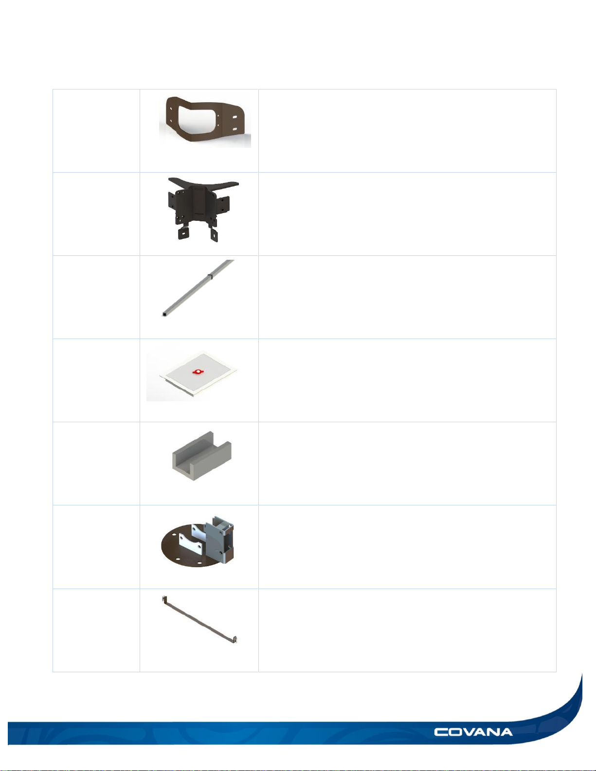
Jack lock
bracket
The jack lock brackets prevent the non-motor-side jacks from
extending during shipping and installation. Do not remove this
bracket until the drive shaft is connecting the motor-side jack to the
non-motor-side jack. Follow the installation steps carefully.
WARNING: There is a risk of injury if this step is not done properly.
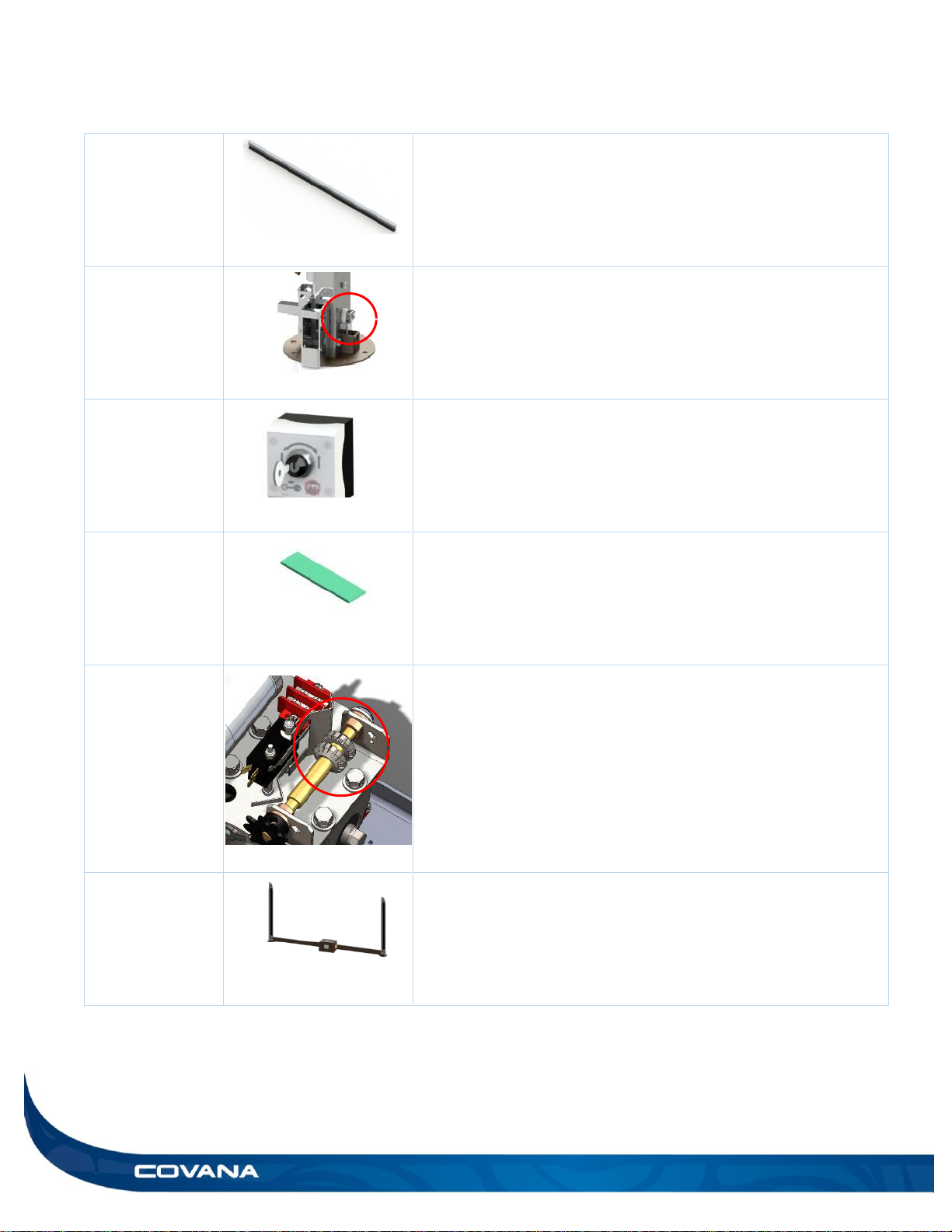
Key switch
The key switch is used to operate the Covana cover.
Installation
foam
The installation foam is used during the installation process to
protect the hot tub from direct contact with the cover. Use the
provided masking tape to temporarily stick the pieces of foam on
the surface of the hot tub.
Limit switch
The limit switches are located in the operator. They control the
minimum and maximum travel height of the Covana cover. Refer to
the Limit Switch Adjustment section for further details.
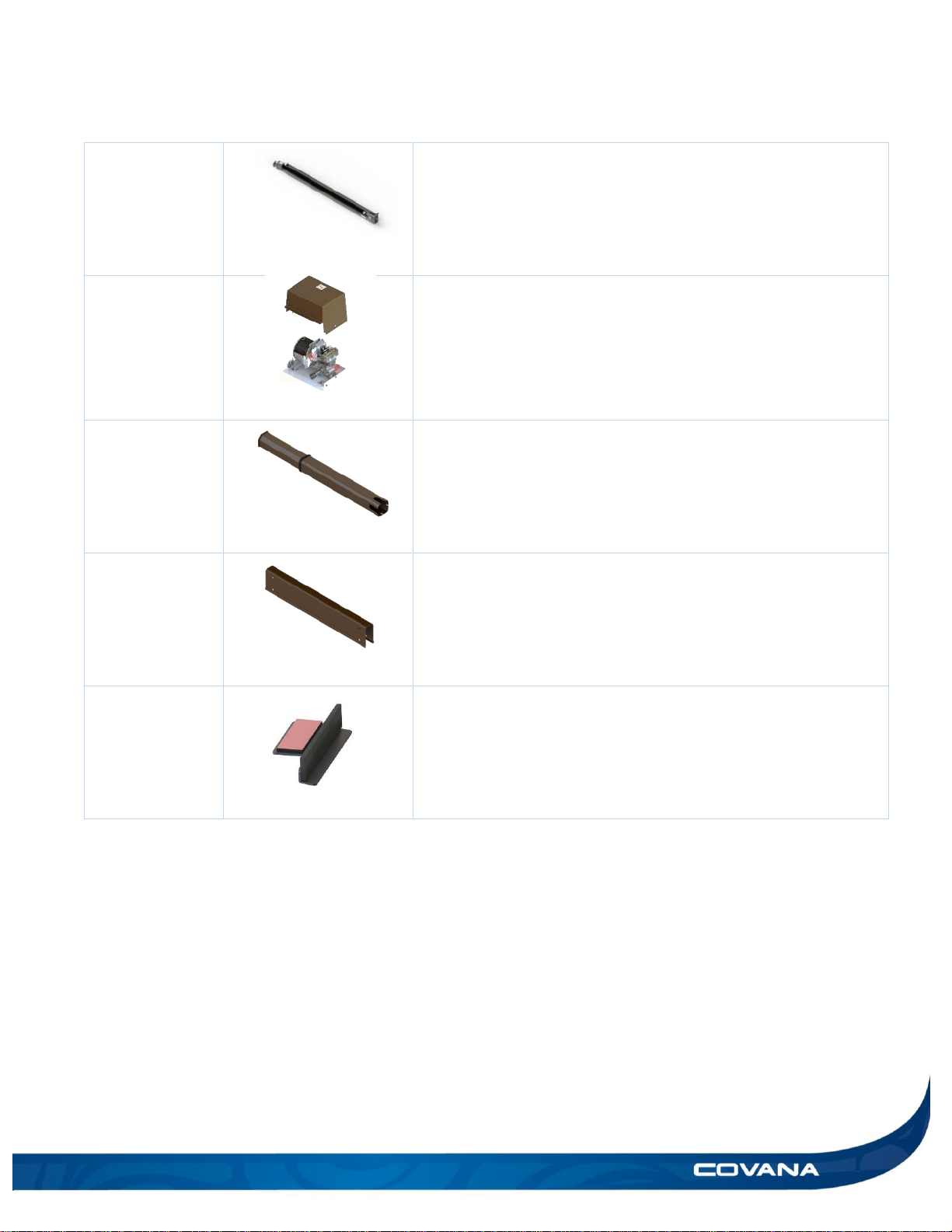
Motor frame
The motor frame is composed of the two motor-side jacks and the
operator.
Figure 15
Figure 18
Figure 19
Figure 16
Figure 17
Figure 14
INSTALLATION MANUAL GLOSSARY 13
Non-motor-side
jack
The non-motor-side jacks are a main part of the Covana cover.
They and the motor-side jacks enable the cover to move.
Operator
The operator powers and controls the lifting mechanism of the
Covana cover. It contains the motor and the limit switches.
Sleeve
The sleeves make up the aluminum case for the lifting mechanism
of the Covana cover. They protect the components and connect the
jacks and the cover.
U-frame
The U-frames protect the mechanical parts resting on the
foundation and connect all four posts.
Wiper bracket
The wiper bracket is adhered under the I-beams using double-faced
tape. This part is required to ensure waterproofing of the Evolution
cover.
Figure 20
Figure 21
Figure 22
Figure 23
Figure 24
14 HARDWARE IDENTIFICATION TABLE INSTALLATION MANUAL
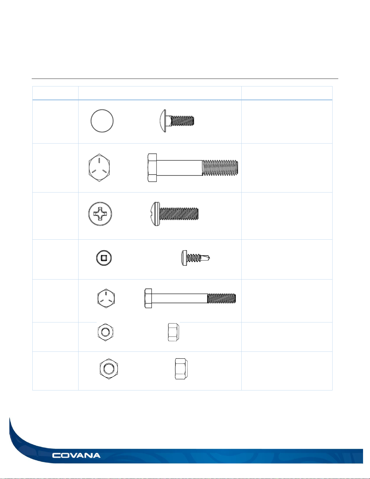
HARDWARE IDENTIFICATION TABLE
Quantity
Visual representation
Description
4
1/4″-20 x 3/4″ carriage bolt
used to assemble the front
frame cut-out.
17
5/16″-18 x 2″ hexagonal bolt
used to assemble the lower
frame.
19
M6 x 20 mm screw used to
hold the inner and outer shell
together.
17
#8 x 1/2″ self-drilling Robertson
screw used to fasten the inner
sleeve to the Covana cover.
4
1/4″-20 x 2 1/4″ hexagonal bolt
used to assemble the feet of
the posts.
8
1/4″″-20 Nylon- insert locknut.
Used to assemble the feet of
the posts and the front cut-out.
17
5/16″-18 nylon-insert locknut
used to connect the U-frames.
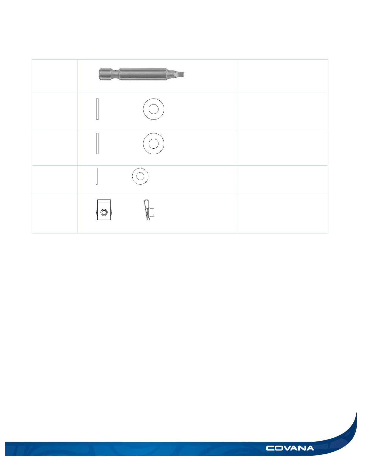
INSTALLATION MANUAL 15
1
#2 x 2″ Robertson bit.
33
5/16″ nylon washer used to
connect the U-frames
17
5/16″ painted washer.
2
1/4″ nylon washers used to
fasten the bottom of the
sleeves with M6 x 20 mm
screw.
2
M6 clip-on barrel nut used to
secure the sleeve at the bottom
of each post.
16 INSTALLATION PREPARATION INSTALLATION MANUAL
INSTALLATION
PREPARATION
To ensure safe use of the Covana cover, it must be
installed on a properly prepared surface. It is
important to adequately prepare the foundation and
carefully read the following recommendations.
Location considerations
Ensure the future Evolution cover location is not
subjected to water downpour or debris falling
from another rooftop.
Ensure that the base of the Covana cover is not
in a flood zone. Any damage caused by flooding
or water accumulation will not be covered under
the warranty.
Ensure there are no obstacles, such as branches
or electrical power lines, in the operating range
of the Covana cover.
Refer to the Technical specifications section for
dimensions of cover.
Ensure there is safe access to the hot tub, free
of obstacles or debris.
All the base components of the Covana cover
must be supported by the foundation.
Ensure the Covana cover is installed on a clean
surface free of any vegetation, such as grass,
branches or roots, or mineral contaminants, such
as rocks, dust or sand.
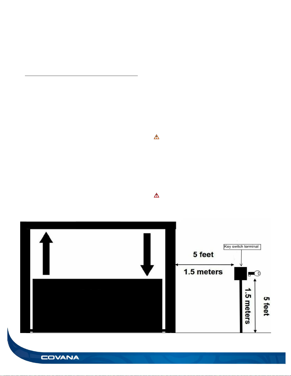
The key switch must be permanently mounted
and located 5 ft. (1.5 m) away from the hot tub
and 5 ft. (1.5 m) above the deck or ground level.
(Figure 25) This ensures the user has a clear
view of the Covana cover when operating it.
Furthermore, the key switch terminal should be
located in a place where no water downpour or
debris could fall on it.
WARNING
Failure to permanently install the key switch as
indicated could cause serious injury or even
death and void the warranty and certification.
Only proper installation of the key switch
combined with the suggested procedures and
caution will reduce such risks.
Do not place the roof in an area prone to snow
accumulation and water runoff.
DANGER
Failure to properly install the key switch
according to these instructions could result in
injury or even death.
Figure 25
Evolution Cover
Spa
INSTALLATION MANUAL INSTALLATION PREPARATION 17
Foundation preparation
The Evolution cover requires a clean, flat and
level surface such as an engineered wood deck
or a concrete slab.
Each of the four jacks of the Covana cover must
be properly anchored to the foundation using at
least one of the pre-drilled holes located at the
foot of each post. Use a 1/4 in. (6 mm) concrete
anchor for concrete pads or a 1/4 in. (6 mm) lag
bolt for wood foundations, and insert minimum
11/4 in. (30 mm) deep. If you cannot meet these
requirements, install a set of non-permanent
mounting plates.
WARNING
The non-permanent mounting plates can only
be used in areas with low winds (less than 30
mph (50 km/h) open and less than 45 mph (70
km/h) in close position).
The non-permanent mounting plates must also
be properly installed.
Just like the hot tub, the Covana cover requires
a solid foundation. The foundation for the
Covana cover must be able to support at least
600 lb. (272 kg).
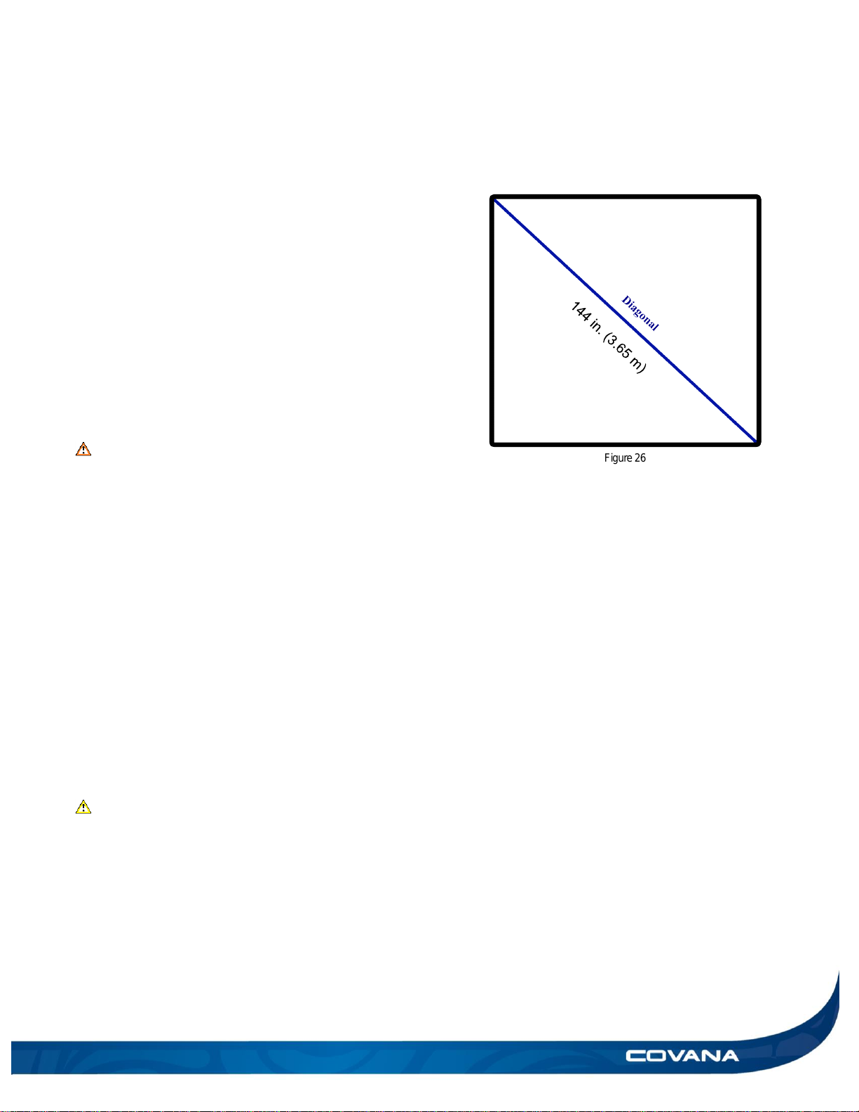
The foundation must be leveled with a
maximum tolerance of 1 in. (2.54 cm) over a
144 in. (3.65 m) diagonal section. (Figure 26).
Refer to Frame dimensions and foot print
section for information on the minimum base
size.
The annual variation in levelness for the same
diagonal section cannot exceed 1/4 in. (6 mm)
CAUTION
Damage caused by inadequate foundation
construction is not covered by the Covana
warranty. It is the responsibility of the owner to
provide a proper foundation.
Failure to follow these guidelines might cause
permanent damage or improper functioning of
the Covana cover. Such damage might not be
covered by the warranty.
Figure 26
 Loading...