

coval LEMAX90X10SB2, LEMAX90X10S, LEMAX90X10SB3, LEMAX90X10SB, LEMAX90X10SB4 Operating Instruction
...
ZA des Petits Champs 26120 Montélier France
tel +33 (0)4 75 59 91 91 - www.coval.com
4.5/7 bar
P=4.5/7 bar
3.5 bar
Vmax=85%
%V
L2=75%
L1=65%
0
0
c
t
t
A
1
Air Saving Control "ASC"
c
%V
0
L1=65%
L2=75%
Vmax=85%
t
CYCLE 1
Air Saving Control (ASC) no ASC
"ASC alarm"
ASC
CYCLE 2 CYCLE 3
2 3
B
LEMAX
modules
- 1 -
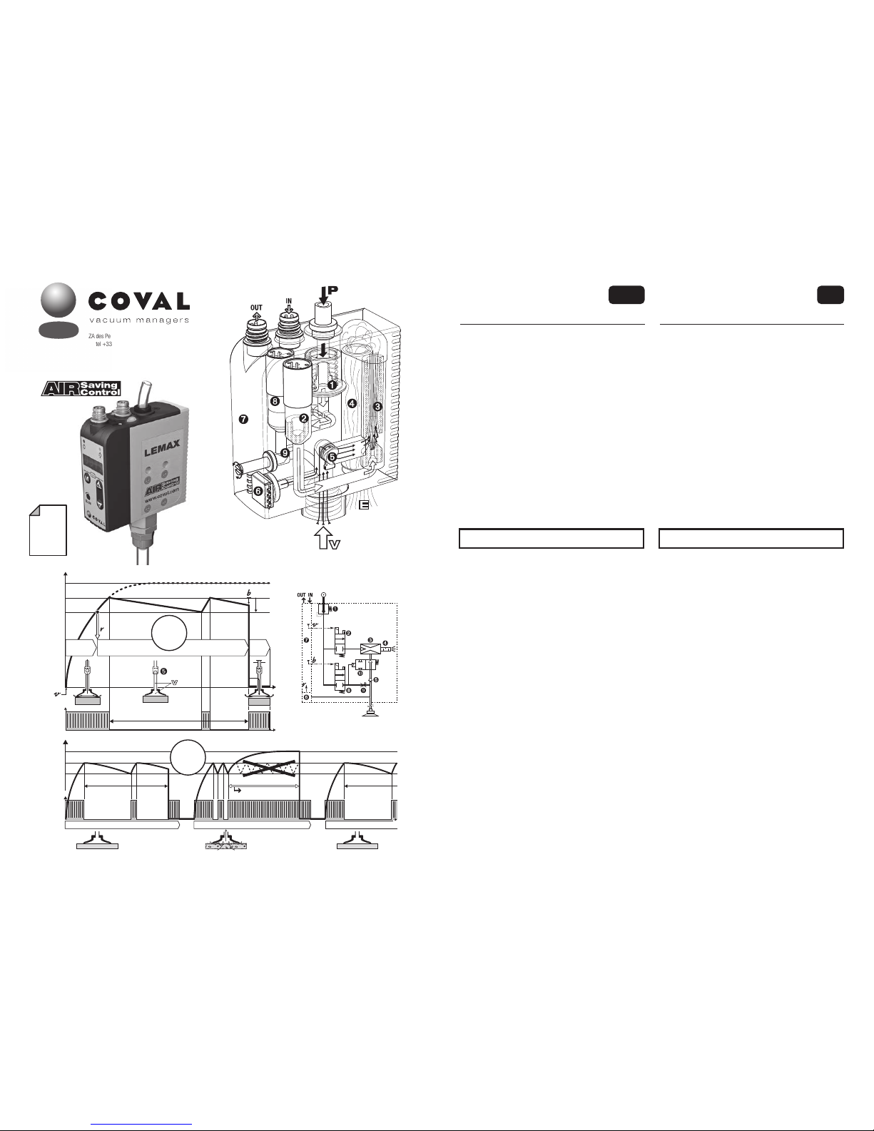
I - WORKING PROCEDURE
The LEMAX vacuum pumps operate with “ASC”: Air Saving Control.
Once vacuum is established, no more air consumption to hold the
product. The resulting energy saving is a key progress. Here is how
it is obtained.
A- The "Air Saving Control" automatic cycle
Example with a LEMAX--X--S module; On this module, the solenoid
valve ➋ is normally closed (NC).
The A diagram presents the 3 steps of the cycle:
1- Product gripping
Pressure regulator* ➊ supplies 3.5 bar to the "vacuum" solenoid
valve ➋. Vacuum signal
v starts the cycle by piloting valve ➋ that
feeds venturi ➌. The generated vacuum grips the product. At 65%
vac., vacuum sensor ➏ generates the "product gripped"
r signal
that authorizes next step.
2- Operations on vacuum gripped product
The operations on the product (transfer, machining…) will start.
When vacuum reaches threshold L2 (75%), the pressure supply
to the venturi is automatically stopped by solenoid valve ➋ no
more consumption. The product remains gripped by vacuum V that
is preserved, due to the closing of poppet ➎. Micro-leaks may lead
to the decrease in vacuum level. Each time it goes below L2-h2
(65%), the vacuum level is regenerated to L2 (75%) thanks to a
brief pressure supply to the venturi.
3- Product release
At the end of operations, release is ordered. "Blow-off" solenoid
valve ➑, piloted by blow-off signal
b, generates an air jet that
closes isolation valve ➓ and, through flow regulator ➒, blows off
the product for a quick release.
B- "Air Saving Control" cycle self-adaptation
The B diagram shows how the module adapts the cycle to fit to the
production realities: leaks due to products, to vacuum pads…
- Here, cycle 1 deals with an air tight product under the influence of
"ASC", resulting in optimum energy savings.
- At cycle 2 however, the porous product generates leaks that
provoke repeated intermittent vacuum regeneration. The anomaly is
automatically detected, and the cycle goes on but without "ASC. A
"ASC missing" signal is then emitted and displayed, and production
goes on.
- Cycle 3 illustrates the automatic return to the "ASC" cycle as
soon as leaks are eliminated: air tight products, vacuum circuit
maintenance…
The LEMAX module thus provides the maximum energy saving,
without any limitations to the performance and functioning of the
overall production system.
integrated compact
vacuum pumps
Operating instruction
ENG
LEMAX
modules
This document is intended for users of LEMAX vacuum pumps in the
following versions:
- LEMAX90X--S - LEMAX90X--SC14
- LEMAX90X--V - LEMAX90X--W
* The pressure regulator ➊ is included on standalone modules only.
V4.0.1 software
h2=10%
I - BETRIEB
Die LEMAX-Vakuumpumpen funktionieren in „ASC“: Air Saving Control.
Sobald das Vakuum hergestellt ist, verbraucht das Modul nicht weiter, um
das Vakuum aufrecht zu erhalten. Die derart erzielte Energieeinsparung
ist ein wesentlicher Fortschritt. Und so wird sie erzielt.
A- Der automatische Air Saving Control-Zyklus
Beispiel mit einem Modul LEMAX--X--S ; bei diesem Modul ist das
Elektromagnetventil ➋ normal geschlossen (NC).
Das Nomogramm A zeigt die 3 Schritte des Zyklus.
1- Werkstückaufnahme
Der Druckregler* ➊ versorgt das „Vakuum“-Magnetventil ➋. Das
Signal
v zum Steuern des Vakuums startet den Zyklus unter Steuern
von ➋, das das Venturi ➌ versorgt. Das dabei erzeugte Vakuum erfasst
das Werkstück. Bei 65 % Vakuum erzeugt der Vakuumschalter ➏ das
Signal r „Werkstückaufnahme“, das den nächsten Schritt erlaubt.
2- Vorgänge an den vom Vakuum gehaltenen Werkstücken
Die Vorgänge an dem Werkstück (Transfer, Bearbeitung,…) finden
jetzt statt. Wenn das Vakuum den Schaltwert L2 (75%) erreicht, wird
die Versorgung der Venturidüse vom Magnetventil ➋ unterbrochen.
Der Druckluftverbrauch sinkt auf null. Das Werkstück wird weiterhin,
durch das Schließen der Klappe ➎, vom Vakuum V gehalten. Das
Vakuumniveau wird hierdurch aufrechterhalten. Mikroleckagen
können das Niveau des Vakuums langsam absinken lassen.
Immer, wenn das Vakuum auf L2-h2 (65%) sinkt, wird eine kurze
Vakuumerzeugung ausgelöst, um auf L2 (75 %) zurückzukehren.
3- Werkstückablegen
Am Ende des Vorgangs wird das Ablegen angesteuert. Das
Magnetventil „Abblasen“ ➑, das vom Signal
b der Abblassteuerung
gesteuert wird, erzeugt einen Luftstrahl, der das Absperrventil ➓
schließt und bläst das Werkstück für ein schnelles Ablegen über die
Durchflusseinstellung ➒.
B- Automatische Anpassung des Air Saving Control-Zyklus
Das Nomogramm B zeigt, wie das Modul den Zyklus in Abhängigkeit
von den Produktionsgegebenheiten anpasst: Lecks auf Grund der
Werkstücke, der Saugnäpfe,…
- Hier verarbeitet der Zyklus 1 ein dichtes Werkstück und läuft in
„ASC“ mit optimaler Energieeinsparung ab.
- Im Zyklus 2 hingegen, kommt ein poröses Werkstück an, dessen Lecks
aufeinander folgende „schlagende“ Verbesserungen des Vakuums
auslösen. Diese Anomalie wird automatisch erkannt und der Betrieb
wird fortgesetzt, allerdings ohne „ASC“. Ein Signal „Ohne ASC“ wird
ausgegeben und angezeigt, die Produktion wird fortgesetzt.
- Der 3. Zyklus veranschaulicht die automatische Rückkehr zum
„ASC“-Betrieb, sobald die Lecks eliminiert sind: das Werkstück ist
dicht, der Vakuumkreislauf wird aufrecht erhalten, …
Das LEMAX-Modul stellt daher die maximale Energieeinsparung sicher,
ohne irgendwelche Zwänge aufzuerlegen und ohne den Betrieb jemals
zu unterbrechen.
Diese Dokument richtet sich an Nutzer der LEMAX Vakuumpumpen,
folgender Versionen:
- LEMAX90X--S - LEMAX90X--SC14
- LEMAX90X--V - LEMAX90X--W
* Der Druckregler ➊ ist nur für die autonomen Module verfügbar.
V4.0.1 Software
Kompakte integrierte
Vakuumpumpen
Bedienungsanleitung
D
LEMAX
modules
1
1
LEMAX90X--S
2
LEMAX90X--V
P=4.5/7 bar
3.5 bar
NC
NF
P=4.5/7 bar
3.5 bar
NO
3
LEMAX90X--W
P=4.5/7 bar
3.5 bar
NO
II
1
LEMFIXA
LEMFIXB
LEMFIXB
2
DIN
35
3
Ø 4
LEMFIXA
Ø 4
64
13.5
Ø 4.2
32.510
64.5
18.5
G1/4"-F
75
85
25
15
76
29.9
6.7
64.5
71.2
35
DIN
LEMFIXA
LEMFIXB
III
- 2 -
II - AUSWAHL DES RICHTIGEN MODULS
Um jede Art von Bedarf zu decken, weist die Produktreihe von LEMAX
autonome und Inselmodule auf, die jeweils eine Steuerung des Vakuums
mit Normalerweise Geschlossenem (NF) und Normalerweise Offenem
(NO) Magnetventil haben. Um Ihr Modul anhand der vorliegenden
Anweisungen effizient zu nutzen, müssen Sie in der Produktreihe anhand
seiner Bezeichnung das passende Modul ausfindig machen.
A- AUTONOME MODULE
1- LEMAX90X--S und LEMAX90X--SC14
Bei diesem Modul ist das Magnetventil ➋ Normalerweise Geschlossen
(NC). Bei Stromausfall wird kein Vakuum mehr erzeugt.
2- LEMAX90X--V
Bei diesem Modul ist das Magnetventil ➋ Normalerweise offen
(NO). Bei Stromausfall wird das Vakuum weiterhin erzeugt, um das
Werkstück zu halten: Sicherheitshalten.
Diese Module werden von ein und demselben Signal
v gesteuert,
das von der Steuerung der Anlage kommt. Für das NO-Modell erfolgt
die Umkehrung des Signals in
v
–
produktintern.
3- LEMAX90X--W
Bei diesem Modul ist das Magnetventil ➋ normalerweise offen NO. Bei
Stromausfall wird das Vakuum weiterhin erzeugt: Sicherheitsfunktion.
In dieser Version NO, steuert das Signal
v "Vakuum aus"
B- INSELMODULE
Alle oben beschriebenen autonomen Module gibt es auch in einer
Inselversion: LEMAX90X
---
B.
Wenn alle Inselmodule identisch sind, wird die Insel zusammengebaut
geliefert: Gegenüberstehend das Modul LEMAX90X
---
B3, eine Insel,
die aus 3 identischen Modulen besteht.
Gehören die Module zu unterschiedlichen Typen, werden sie einzeln
geliefert, jedes mit einem Satz von Endteilen, die für ihr Zusammenbauen
vor Ort in Abhängigkeit von den Erfordernissen der Anlage nötig sind.
Jedes Inselmodul wird von der gemeinsamen Druckversorgung, die die
ganze Insel durchquert, versorgt (siehe Skizze).
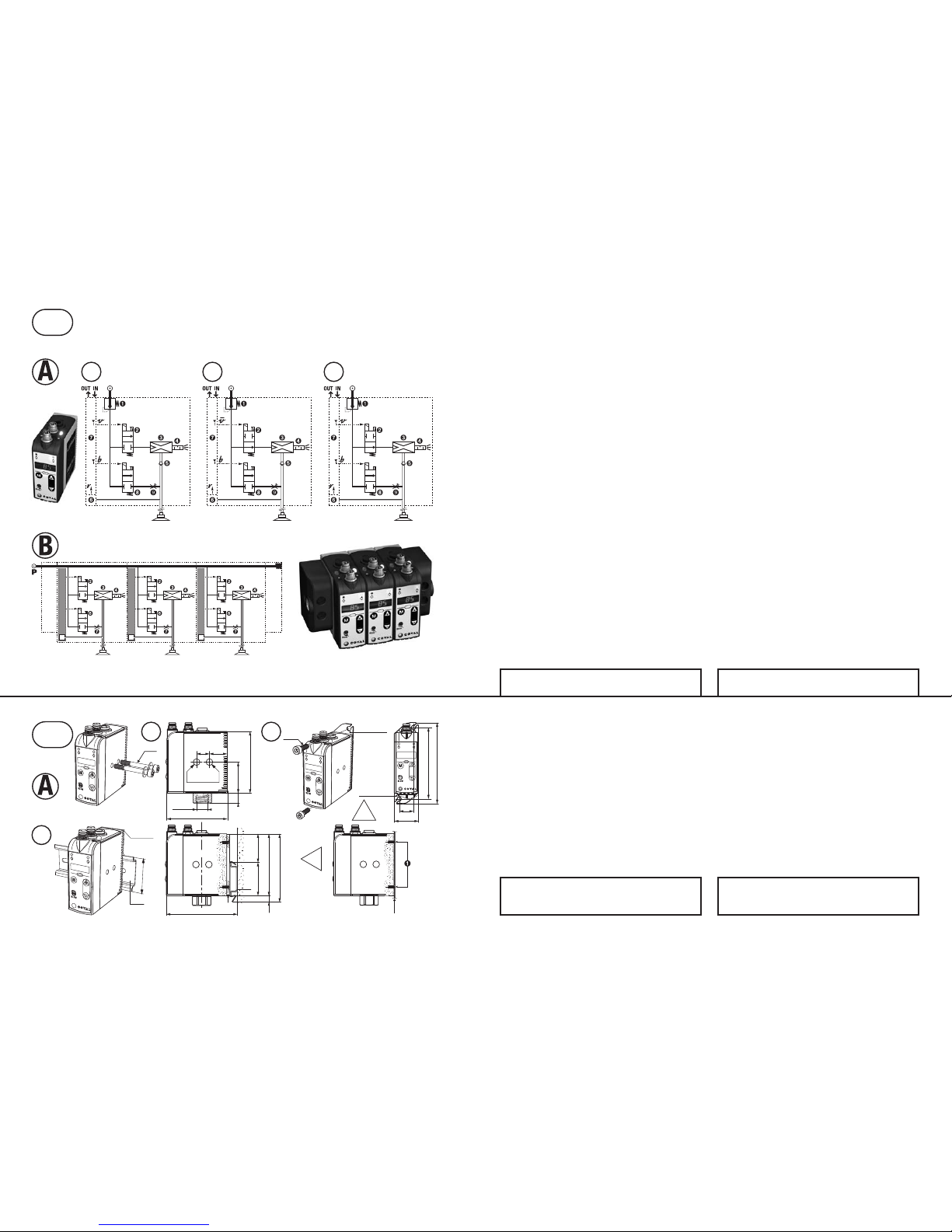
III - ANORDNUNG
A- AUTONOME MODULE
Auswahl aus 3 Anordnungstypen:
1- Befestigung von der Seite
2 durchgehende Schrauben Ø 4 mm mit breiten Unterlegscheiben
unter den Köpfen.
2- Befestigung von vorn
- Das Modul mit den 4 mitgelieferten Schrauben ➊ auf die LEMFIXA
Platte schrauben.
- Befestigung mit 2 Schrauben Ø 4 mm.
3- Befestigung auf DIN-Schiene
- Das Modul mit den 4 mitgelieferten Schrauben ➊ auf die LEMFIXB
Platte schrauben.
- Das Modul mit dem Clip der Platte LEMFIXB auf die Schiene zu 35
mm clipsen.
Wichtig
Für kurze Reaktionszeiten und einen minimalen Verbrauch, ordnet
man das Modul möglichst nahe an den Saugnäpfen an.
III - MOUNTING
A- STAND-ALONE MODULES
Mounting options: 3 types
1- Mounting from side
2 protruding screws Ø 4mm with large washers.
2- Mounting from front
- install the fixing plate LEMFIXA with 4 screws ➊ furnished with
product.
- Mount with 2 screws Ø 4mm .
3- Mounting over a DIN rail
- Fix the plate LEMFIXB on the module with the 4 screws ➊ furnished
with the product.
- Clip on the module over the 35 mm DIN rail, with the plate LEMFIXB clip.
Important
For short response times and minimum consumption install the
module close to suction pads.
II - IDENTIFYING YOUR MODULE
In order to answer ta all needs, the LEMAX range includes stand-alone
and island modules, each of them with a vacuum solenoid valve either
NC or NO. For an efficient installation of your LEM module with the
current operating instructions, it is necessary to identify your module
with the help of its specific reference.
A- STAND-ALONE MODULES
1- LEMAX90X--S and LEMAX90X--SC14
On this module, solenoid valve ➋ is Normally Closed (NC). In case
of electrical cut-off, the vacuum generation stops.
2- LEMAX90X--V
On this module, solenoid valve ➋ is Normally Open (NO). In case
of electrical cut-off, the vacuum generation goes on to hold the
product: positive security.
These modules are controlled by the same
v signal provided by
the installation control. In fact, for the NO version, the inversion of
the signal to
v
–
is internal to the product.
3- LEMAX90X--W
On this module, solenoid valve ➋ is normally open (NO). In the
event of an electrical failure, vacuum continues to be generated,
thus holding the part: product safety.
In this NO version, the signal
v controls the vacuum shutdown.
B- ISLAND MODULES
All stand-alone modules described above also have a version to be
island assembled : LEMAX90X
---
B.
If all modules in an island are identical, this island is supplied all
assembled : see example LEMAX90X
---
B3, 3 identical modules
island.
If modules are different, they are supplied separately, together with the
island end set to complete the assembling on site in accordance to the
requirements of the application.
In the island, each module is fed by common pressure covering the
whole island (see figure).
The switching type of the inputs / outputs can be set to PNP (by
default) or NPN (see IX-4).
Der Schaltmodus der Ein- / Ausgänge ist in PNP (Standard) oder
NPN (siehe IX-4) konfigurierbar.

Ø4.2
Ø4.2
Ø4.2
Ø4.2
25 2020
LEMAX90X
---
B3
Torx T8
25 x n LEMAX + 20
25 x n LEMAX + 40
2
3 4
20
25
25
25 x n LEMAX + 40
25
1
64.5
25
10
24.515
37
0.5
64.5
26
G1/4"-F
64.5
7.5 2235
65.5
DIN
71
clip
33.5
10
G1/4"-F
B
L
A
A
A
B
P 4.5/7 bar
Ø6
1.0 mm
1.2 mm
1.4 mm
2 3 4 5 6 7 8 9
Simultaneously active module number
Anzahl der gleichzeitig aktiven Module
nozzle ID
Düse ID
G1/8"-F
P = 4 bar
B
B
d
D
G1/4"-F
IV - TUBE CONNECTIONS
A- CONNECTION FOR PRESSURE SUPPLY
- 5µ filtered, non-lubricated air relevant to standard ISO 8573-1:2010
[4:5:4].
1- Stand-alone modules
- Push fitting for 6 mm OD tube (A).
- Network pressure P = 4.5 to 7 bar.
2- Islands
- Side connection on threaded port G1/8"-F (A), on one or both island
ends, depending upon simultaneously active number and size of
units: nozzle ID 1.0 mm, 1.2 mm or 1.4 mm.
Follow table recommendations.
- Pressure preferably regulated to 4 bar for energy savings and noise free
performance (island stacked modules have no integrated regulator).
B- VACUUM CIRCUIT CONNECTION
For an optimum performance with "Air saving control" it's a must to
maintain the airtightness of the vacuum network at all times. If there is
movement of the vacuum tube with respect to the module, a compresssion
fitting (illustration) is recommended to assure an air-tight connection.
see COVAL catalogue, fittings choice for tubes dxD= 4x6 mm, 6x8
mm, 8x10 mm.
Important: for short response times and minimum consumption it
is advised to reduce the volume to be evacuated.
While doing this, the module is installed closed to the suction pads
and the length L of the tube connecting the suction pads is as short
as possible.
Note : module's protection
- Vacuum entry sieve
A 200 µ sieve, integrated in port B, protects the module by stopping
any abrasive particle (sand…).
- Possible additional filter on vacuum circuit
In the rare cases of thin dust in wet environment, an adequate filter
will prevent any clogging:
see COVAL catalog, "vacuum circuit filters".
IV - ANSCHLÜSSE
A- ANSCHLUSS DER DRUCKVERSORGUNG
- Gefilterte, nicht geölte Luft, 5 µm gemäß Norm ISO 8573-1:2010
[4:5:4].
1- Autonome Module
- Schnellkupplung für Schlauch Ø 6 mm (A).
- Druck des Netzes: P = 4.5 bis 7 bar.
2- Inseln
- Anschluss an Gewindeöffnung G1/8"-F (A), auf einer oder auf beiden
Seiten der Insel, in Abhängigkeit von der Anzahl der gleichzeitig aktiven
Module und von ihrer Leistung : Düsen Ø 1 mm, 1,2 mm oder 1,4 mm.
Die Anweisungen der links stehenden Tabelle einhalten.
- Druck vorzugsweise zum Energiesparen und für ruhigen Betrieb auf
4 bar entspannt (die vereinten Module haben keinen integrierten
Druckminderer).
B- ANSCHLUSS AN VAKUUMKREISLAUF
Für einen zufriedenstellenden „Air Saving Control“, muss der Vakuumkreislauf dauerhaft dicht sein. Wenn sich der Schlauch in Bezug zum Modul
bewegt, wird ein Anschluss mit geschraubter Kappe (Abbildung) empfohlen.
Siehe COVAL-Katalog, Auswahl der Schlauchanschlüsse dxD =
4x6 mm, 6x8 mm und 8x10 mm.
Wichtig: für kurze Reaktionszeiten und einen minimalen Verbrauch,
ordnet man das Modul möglichst nahe an den Saugnäpfen an. Dazu
und weil das Modul möglichst nahe an den Saugnäpfen angeordnet
wird, muss dafür gesorgt werden, dass die Länge L des Schlauches,
das sie mit dem Modul verbindet, möglichst kurz gehalten wird.
Hinweis: Schutz des Moduls
- Siebfilter am Eingang des Vakuums
In die Öffnung B ist ein Siebfilter zu 200 µ eingebaut, um das Modul
zu schützen und scheuernde Partikel aufzufangen (Sand usw.).
- Eventuell zusätzlicher Filter auf dem Vakuumkreislauf
In seltenen Fällen, wenn feiner Staub in feuchter Umgebung vorliegt,
vermeidet ein entsprechender Filter ein internes Verstopfen:
siehe Katalog COVAL „Filter für Vakuumkreisläufe“.
IV
- 3 -
B- INSELMODULE
1- Zusammengebaute Inseln
Wenn es sich um Module des gleichen Typs handelt, wird die
Insel zusammengebaut geliefert, zum Einbauen, Verbinden und
Anschließen bereit.
2- Zusammenbauen einer Insel
Die Module sind unterschiedlichen Typs und werden in Abhängigkeit
von den Erfordernissen der Anlage in Inseln angeordnet. Das
Zusammenbauen erfolgt durch einfaches Schrauben eines Moduls
auf das andere, mit einem Schraubendreher Torx T8 (Abbildung).
3- Befestigen einer Insel von vorn
mit 2 durchgehenden Schrauben Ø 4 mm.
4- Befestigung einer Insel auf DIN-Schiene
Der Befestigungsbausatz LEMFIXC besteht aus 2 Schrauben und 2
Clips, um jedes der Enden der Insel auszustatten. Die Insel wird auf
das DIN-Profil geclipst.
Anmerkung: Alle Maßangaben in mm.
B- ISLAND MODULES
1- Pre-assembled island
With all identical modules, the island is supplied all assembled,
ready for fixation and connections.
2- Island assembly
When different, the modules may be positionned into the island
according to the installation needs.
Assembly is easily made by screwing each module on the other,
using a T8 Torx screw driver (illustration).
3- Island mounting from front
2 protruding screws Ø 4mm.
4- Island mounting over a DIN rail
Fixing set LEMFIXC provides 2 screws and 2 clips to equip each
island end. The island may then be clipped over the DIN rail.
Note: All dimensions are in mm.

OUT
IN
(LEMAX90X--S / LEMAX90X--V / LEMAX90X--W)
B1 A1
214
3
214
3
OUT
24 V
5 V
0 V 0 V
IN
CDM8
OUT IN
CCM8
B2
B3
A2
(LEMAX90X--S)
214
3
214
3
24 V
1
➝
5 V
0 V
0 V
V
VI
PNP
NPN
V - ELECTRICAL CONNECTIONS
The LEMAX vacuum pump must be used with power supply units
that provide a Protective Extra Low Voltage (PELV) and with an
isolation of the supply voltage according to EN60204.
The electrical connections to be made depend of the module use,
which will also correspond to a specific configuration illustrated in
chapter IX.
A- IN connections
PIN 3 (blue wire) ➞ 0V permanent.
PIN 2 (white wire):
- LEMAX90X version --S / LEMAX90X version --V ➞ vacuum
command
v .
- Version LEMAX90X--W ➞ command
v = vacuum stop.
A1- Connection for blow-off controlled by specific signal
PIN 4 (black wire) ➞ blow-off command
b.
A2- Connection for automatic-timed blow-off (see VIII-3)
PIN 4 (black wire) ➞ no connection.
note : automatic-timed blow-off only on LEMAX90X--S.
B- OUT connections
Permanent supplies:
PIN 3 (blue wire) ➞ 0V PIN 1 (brown wire) ➞ 24V
PIN 4 (black wire) ➞ switching output
r
B1- Connection for "ASC missing" signal (see VIII-2)
PIN 2 (white wire) ➞ output “ASC missing” signal + 5V DC output NO.
B2- Connection for "vacuum level" signal (see VIII-2)
PIN 2 (white wire) ➞ output analogic signal 1 to 5V DC.
B3-Connection version LEMAX90X--SC14
PIN 2 (white wire) ➞ vacuum control
v
VI - DIALOGUE PANEL
A- Dialogue
Visual indicator v signal vacuum command (green).
Visual indicator
b signal blow-off command (orange).
Vacuum manual override.
Blow-off manual override.
Operation indicator "vacuum" (green).
Operation indicator "blow-off"(orange).
3 digit digital display.
Visual indicator "gripped product" (green).
Keyboard: configurations and settings.
Blow-off flow regulator.
B- Configuration
3 digit digital display :
- configuration and diagnostics interface
- production follow-up.
Keyboard
:
- M: mode selection.a
- + & −: value selection.
V - ELEKTROANSCHLÜSSE
Die LEMAX-Vakuumpumpe erfordert die Verwendung von
Schutzkleinspannung (= PELV - Protective Extra Low Voltage)
und eine sichere Trennung von der Versorgungsspannung nach
EN60204.
Die herzustellenden elektrischen Anschlüsse hängen vom
Gebrauch des Moduls ab, von dem auch ein Parametrieren, in
Kapitel IX angegeben, abhängt.
A- Anschlüsse IN
PIN 3 (blauer Leiter) ➞ 0V permanent.
PIN 2 (weißer Leiter):
- Version LEMAX90X--S / LEMAX90X--V ➞ Vakuumsteuerung
v .
- Version LEMAX90X--W ➞ command
v = Vakuumstopp.
A1- Anschluss für durch spezifisches Signal gesteuertes Abblasen
PIN 4 (schwarzer Leiter) ➞ Abblassteuerung b .
A2-Anschluss für Self-Timed Abblasen (siehe VIII-3)
PIN 4 (schwarzer Leiter) ➞ kein Anschluss.
Hinweis: Das Self-Timed Abblasen ist nur auf LEMAX90X--S
verfügbar.
B- Anschlüsse OUT
Ständige Versorgungen:
PIN 3 (blauer Leiter) ➞ 0V PIN 1 (brauner Leiter) ➞ 24V
PIN 4 (schwarzer Leiter) ➞ Signalausgang
r
B1- Anschluss für das Signal „ohne ASC“ (siehe VIII-2)
PIN 2 (weißer Leiter) ➞ Signalausgang „ohne ASC“ + 5 V DC NO.
B2- Anschluss für das Signal „Vakuumlevel“ (siehe VIII-2)
PIN 2 (weißer Leiter) ➞ Ausgang für Analogsignal 1 bis 5 V DC.
B3- Anschlussversion LEMAX90X--SC14
PIN 2 (weißer Draht) ➞ Vakuumkontrolle
v
VI - ANZEIGE UND BEDIENFELD
A- Zustand und Bedienfeld
Anzeigelampe Steuersignal des Vakuums v (grün).
Anzeigelampe Steuersignal des Abblasens
b (orange).
Manuelles Steuern des Vakuums.
Manuelles Steuern des Abblasens.
Statusanzeige „Vakuums“ (grün).
Statusanzeige „Abblasen“ (orange).
Anzeige 3-Stellig 7 Ziffern.
Anzeige „Objekt angesaugt“ (grün).
Tastatur: Parametrierung und Einstellung.
Einstellung des Abblas-Volumenstroms.
B- Konfiguration
Anzeige 3-Stellig 7 Ziffern :
- Bedienfeld für Parametrierung und Einstellung.
- Betriebsüberwachung.
Bedientastatur
:
- M: Auswahl der Betriebsart.
- + & −: Auswahl des Werts.
BN: brown
BK: black
BU: blue
WH: white
The switching type of the inputs / outputs can be set to PNP ( by
default) or NPN (see IX-4).
Der Schaltmodus der Ein- / Ausgänge ist in PNP (Standard) oder
NPN (siehe IX-4) konfigurierbar.
+ 24V DC
v
b
0V DC
LEMAX PNP IN
2 WH
4 BK
3 BU
LEMAX NPN IN
v
b
0V DC
2 WH
4 BK
3 BU
R
L
1 BN
+ 24V DC
5 V DC / 1➞5V
r
0V DC
LEMAX PNP OUT
2 WH
4 BK
3 BU
R
L
1 BN
+ 24V DC
r
5 V DC / 1➞5V
0V DC
LEMAX NPN OUT
4 BR
2 WH
3 BU
214
3
24 V
0 V
- 4 -
 Loading...