

Country Hearth 2200iA Owner's Operation And Instruction Manual

Owner’s Operation and Instruction Manual
C
S
S
U
C
O
M
P
A
N
Y
U
N
I
T
E
D
S
T
A
T
E
S
S
T
O
V
E
MODEL: 2200iA
Fireplace Insert
Masonry Fireplace Insert or Zero-Clearance (metal) Fireplace Insert
SAFETY TESTED TO UL 1482-2010 and ULC-S628-1993
Also tested to Australian Standards: AS/NZS 4012:1999, AS/NZS 4013:1999 and AS/NZS 2918:2001
US ENVIRONMENTAL PROTECTION AGENCY PHASE II CERTIFIED WOODSTOVE
See Appendix A for Special Australian Installation, Operation and Safety Requirements.
DO NOT use this appliance in a mobile home, manu-
CAUTION!
Please read this entire manual before you install and use your new
heater. Failure to follow instructions
may result in property damage,
bodily injury, or even death.
THIS MANUAL WILL HELP YOU TO OBTAIN EFFICIENT, DEPENDABLE SERVICE FROM THE HEATER, AND ENABLE YOU TO
ORDER REPAIR PARTS CORRECTLY. KEEP IN A SAFE PLACE FOR FUTURE REFERENCE.
French version is available for download from the U. S. Stove website: http://www.usstove.com/
United States Stove Company
South Pittsburg, TN 37380, USA
factured home, trailer, or tent.
SAFETY NOTICE:
If this heater is not properly installed, a house fi re may
result. For your safety, follow the installation instructions.
Contact local building or fi re offi cials about restrictions
and installation in your area.
SAVE THESE INSTRUCTIONS
227 Industrial Park Road
P.O. Box 151
1-800-750-2723
852161

CONGRATULATIONS!
You’ve purchased a heater from North America’s oldest manufacturer of wood burning products. By heating with wood
you’re helping to CONSERVE ENERGY! Wood is our only Renewable Energy Resource. Please do your part to pre-
serve our wood supply. Plant at least one tree each year. Future generations will thank you.
The instructions pertaining to the installation of your wood stove comply with UL-1482 and ULC-S628 standards.
SAFETY INSTRUCTIONS
1. The installation of this appliance must comply with your local
building code rulings.
2. DO NOT INSTALL THIS APPLIANCE IN A MOBILE HOME,
MANUFACTURED HOME, TRAILER OR TENT (NO EXCEPTIONS PER HUD FEDERAL STANDARD: 24 CFR CH.XX).
3. Verify that the appliance is properly installed before fi ring for
the fi rst time. This appliance should be installed by a qualifi ed
installer to insure a correct and safe installation. NEVER use
temporary or makeshift compromises during the installation.
4. If there are any missing or damaged components of the appliance, contact your dealer immediately. DO NOT OPERATE
THIS APPLIANCE WITH MISSING OR DAMAGED PARTS.
5. WARNING: RISK OF FIRE. Observe the minimum clearances to combustibles stated in this manual and on the labels
attached to the appliance. DO NOT store wood, any type
of fl ammable vapors or liquids, place furniture, rugs,
carpet, clothing or other combustible objects within the
clearance area.
6. DO NOT connect this appliance to any air distribution duct
or system.
7. DO NOT tamper with the combustion air control of this unit
beyond normal adjustment range.
8. Provide adequate combustion air to the room where the appliance is installed. Restricting combustion air will result in a
lazy fi re which causes soot or creosote buildup and greatly
reduces effi ciency.
9. Always connect this appliance to a chimney that vents to the
outside. Never vent into another room, crawl space, attic,
or inside a building. DO NOT CONNECT THIS UNIT TO A
CHIMNEY FLUE SERVING ANOTHER APPLIANCE.
10. DO NOT connect a wood burning appliance to an aluminum
Type B gas vent. This is not safe. Use approved masonry
or a UL 103 HT (U.S.) Listed Residential Type and Building
Heating Appliance Chimney. Use a 6” diameter chimney, that
is high enough to create suffi cient draft.
11. Be sure your chimney is safely constructed and in good
repair. Have the chimney inspected by the fi re department
or a qualifi ed inspector. Your insurance company should be
able to recommend a qualifi ed inspector.
12. Creosote or soot may build up in the chimney liner or chimney
and cause a house/building fi re. Inspect the chimney and
chimney liner twice monthly during the heating season and
clean if necessary.
13. In the event of a chimney fi re, turn the air controls to the
closed position, leave the building and CALL THE FIRE
DEPARTMENT IMMEDIATELY!
14. To prevent injury, do not allow anyone to use this appliance
that is not familiar with its correct operation. Do not operate
this appliance while under the infl uence of alcohol or drugs.
15. CAUTION: HOT SURFACES. KEEP CHILDREN AWAY.
DO NOT TOUCH WHILE IN OPERATION. CONTACT MAY
CAUSE SKIN BURNS.
2 Ussc
16. Children should be alerted to the hazards from high surface
temperatures. Never leave small children unsupervised
when they are in the same room as the appliance during
operation. To prevent burns, always wear protective clothing,
leather hearth gloves, and eye protection when refueling or
fi re maintenance. Always be aware of heated surfaces. Heat
radiating from the appliance can potentially discolor, melt,
or even ignite combustible materials. KEEP ALL COMBUS-
TIBLE MATERIALS WELL AWAY FROM THE HEATER!
17. WARNING: RISK OF FIRE. Keep the feed door tightly closed
at all times except when tending the fi re.
18. DO NOT overfi re this appliance. Overfi
feed door is left open during operation. If any part of the
appliance glows, you are overfi ring. Adjust air controls to a
lower setting to slow down the fi re.
19. DO NOT ELEVATE THE FIRE! Build the fi re directly on the
fi rebrick. This appliance has not been tested with the use of
any means to elevate the fi re and it should not be attempted.
20. Ashes should not be allowed to accumulate more than two
to three inches in the fi rebox.
21. The paint on your appliance is durable but will not stand rough
handling or abuse. The paint used may give off smoke and/or
an odor during the fi rst few fi res. This will occur until the paint
has cured. Animals / people with lung problems should not
be present during the curing process. Build small fi res at fi rst
to help this process and open windows and doors as needed
to clear the smoke and odor. If the appliance is overfi red,
the paint will discolor. When installing your unit, take care
in handling. Clean with soap and water when the appliance
is not in use. Do not use any acids, abrasive cleaners or
scouring soap as these solvents wear and dull the fi nish.
22. DO NOT ROUTE THE BLOWER POWER SUPPLY CORD
NEAR OR ACROSS HOT SURFACES!
23. Canada Installations requires that this fi replace must be
installed with a continuous chimney liner of 6 inch diameter
extending from the fi replace insert to the top of the chimney.
The chimney liner must conform to the Class 3 requirements
of CAN/ULC-S635, Standard for Lining Systems for Existing Masonry or Factory-Built Chimneys and Vents, or CAN/
ULC-S640, Standard for Lining Systems for New Masonry
Chimneys.
24. Permanently seal any opening between the masonry of the
fi replace and the facing masonry.
25. Fireplace insert surround panels may be removed to inspect
fi replace insert and fi replace.
26. U.S. Stove Company requires installing smoke detectors in
the same room as the heater if not already installed. Smoke
expelled from the unit by either paint curing, opening the fuel
loading door, or a negative pressure inside the home could
trigger the smoke detectors.
27. For further information on using your heater
a copy of the National Fire
publication “Using Coal and Wood Stoves Safely” NFPA No.
HS-10-1978. The address of the NFPA is 1 Battery March
Park, Quincy, MA. 02269.
Protection Association (NFPA)
ring will occur if the
safely, obtain
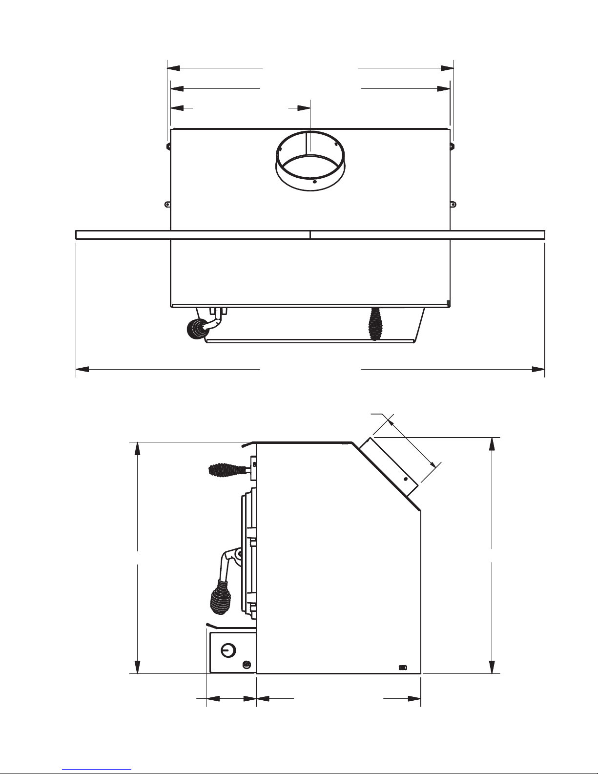
2200I DIMENSIONS
27 1/32 [686.6 mm]
26 11/32 [669.0 mm]
13 5/32 [334.5 mm]
21 13/16 [554.0 mm]
44 7/32 [1123.0 mm]
P6.00 INSIDE
22 1/4 [565.0 mm]
Ussc 3
15 1/2 [394.0 mm]4 11/16 [118.8 mm]
PRE-INSTALLATION REQUIREMENTS
FIREPLACE CONDITION AND
ZERO CLEARANCE REQUIREMENTS
A masonry fi replace must meet minimum code require-
ments, National Fire Protection Association, (NFPA) 211,
or the equivalent for a safe installation. Contact a professional, licensed installer, your local building inspector or
the local fi re authority for the requirements in your area.
Your insurance company should be able to recommend a
qualifi ed inspector.
Inspections should include the following:
1. Condition of the fi replace and chimney. A masonry
fi replace and chimney MUST be inspected prior to installation of this appliance. They must be free from
cracks, loose mortar, creosote deposits, blockage or
other evidence of deterioration. If found, these items
MUST be repaired prior to installation. DO NOT REMOVE BRICKS or MORTAR from existing fi replace
when installing this unit.
2. Chimney Size. Minimum chimney size is 6˝ (152mm)
diameter. Maintain a 15 ft. minimum overall chimney
height measured from the top of appliance to the top
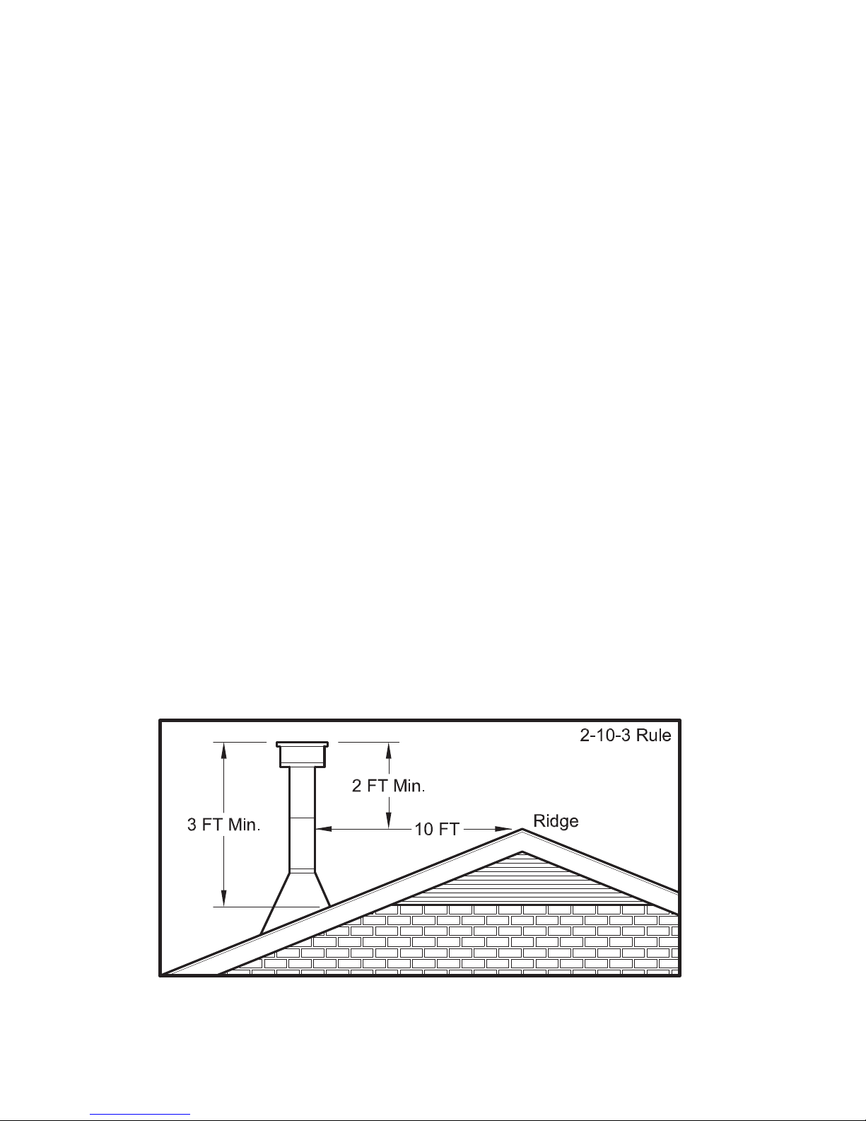
of the chimney. Chimneys must extend at least 3 ft.
above the roof and at least 2 ft. above the highest
point within 10 ft. of the chimney top. See the Chimney Connections section of this manual.
3. Zero Clearance or Metal Heatform Fireplaces.
These fi replaces and chimneys must meet the mini-
mum code specifi cations as noted above. Factory
built zero clearance fi replaces must be listed and
suitable for solid fuel use. Chimneys must be at least
7 inch diameter to accommodate a required, continuous, stainless steel liner from the appliance’s fl ue col-
lar to the top termination of the chimney.
Only detachable parts that can be easily replaced (i.e.
damper parts, screens, doors and side, and back refractory panels) are to be removed. These parts must
be stored and readily available for replacement if the
appliance is ever removed. The removal of any parts
that render the fi replace unusable for burning solid
fuel requires a permanent label to be affi xed by the in-
staller that states the fi replace is unsuitable for burn-
ing solid fuel unless the missing parts are replaced
and the fi replace is restored to its original, certifi ed
condition.
4. Chimney Caps. Mesh type chimney caps and spark
arrestors must be able to be removed for regular inspection and cleaning. Otherwise the mesh should be
removed to prevent possible plugging. Check your local fi re and building codes.
5. Chimney Liner. The chimney must be suitable for
burning solid fuel. Install a continuous stainless steel
liner from the fl ue collar of the appliance to the top of
the chimney. Liner must be UL Listed to UL1777.
4 Ussc
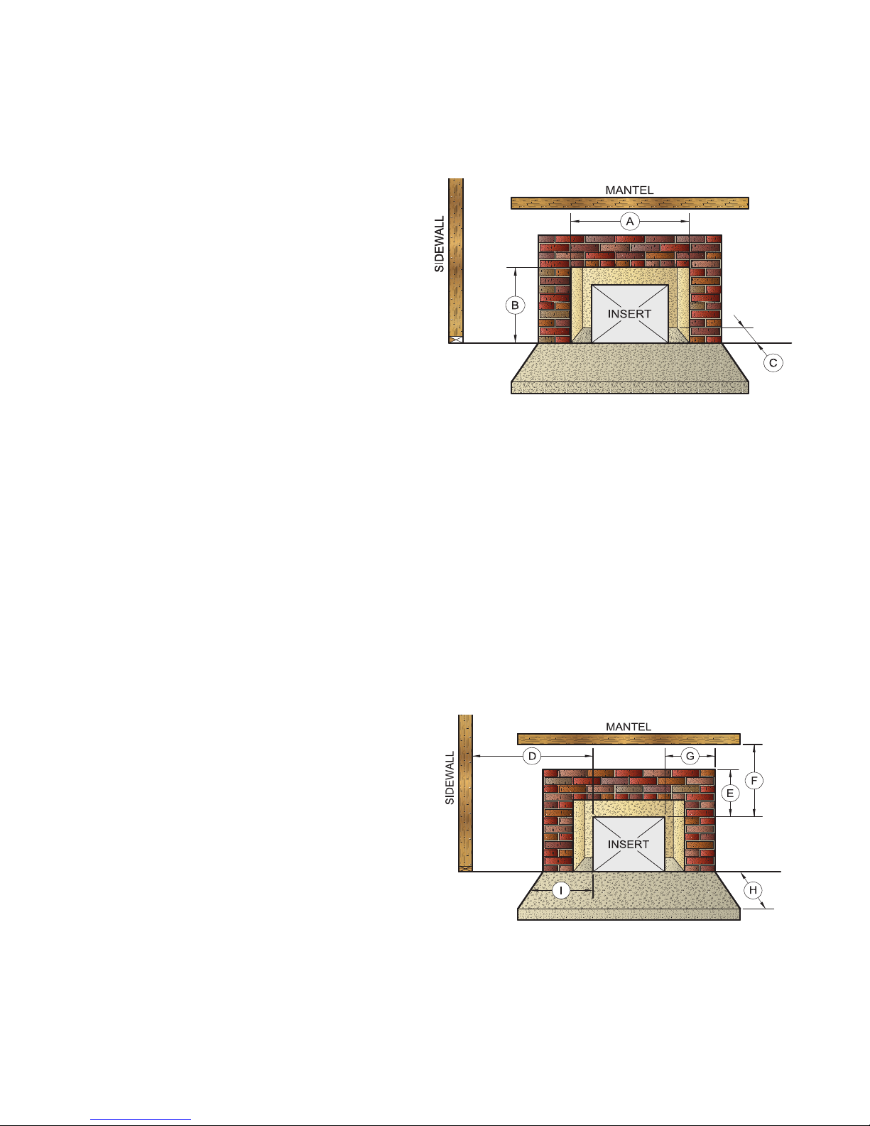
6. Fireplace Opening Dimensions.
A. Minimum Width ...............................29˝ [737mm]
B. Minimum Height ..............................23˝ [584mm]
C. Minimum Depth ..............................14˝ [356mm]
7. Combustible Material Clearances. The fi replace
and chimney must be inspected to make sure there
is adequate clearance to combustible materials. This
includes the top, side, front, and back as well as
concealed combustibles in the chimney and mantle
areas. Your local building inspector or fi re authority
should have information on whether older fi replace
meet current codes and are suitable for use. See also
fi gure 1 and fi gure 2.
D. Min. Distance to Sidewall ..................9˝ [228mm]
E. Min. Distance to Top Trim ................14
F. Min. Distance to Mantle ...................19˝ [482mm]
G. Min. Distance to Side Trim .................9˝ [228mm]
H. Min. Floor Protector Front ................12˝ [304mm]
I. Min. Floor Protector Side ...................6˝ [152mm]
Min. Floor Protector Side Canada ....8” [203]
8. Makeup Air Requirements. This appliance requires
an adequate supply of makeup air to operate safely
and effi ciently. In some areas, this is a building code
requirement. Inadequate air supply will cause poor
combustion, ineffi cient operation, creosote buildup,
back drafting and smoke puffi ng into the living areas.
If any of the following conditions are evident, a makeup air supply MUST be installed.
˝ [355mm]
PRE-INSTALLATION REQUIREMENTS continued...
a. Existing fuel-fi red equipment shows evidence of
back puffi ng, smoke roll-out, ineffi cient operation,
or excessive smell in the living area.
b. Opening a window or door alleviates any of the
above problems or symptoms.
c. The building is constructed with a well-sealed va-
por barrier, tight fi tting windows, or has powered
exhaust fans.
d. Excessive condensation on windows in the winter.
e. The building has a ventilation system installed.
f. If, once installed, the solid-fuel appliance does not
draw steadily, burns poorly or ineffi ciently, back-
drafts or experiences back-puffi ng when adding
fuel.
VENTING (DRAFT) REQUIREMENTS
The chimney fl ue is a critical component to the proper and
effi cient operation of any heating appliance. Heating appli-
ances do not create draft, draft is provided by the chimney.
This appliance requires a draft of 0.05 in. water column
(0.1 Pa) at the fl ue collar.
WARNING: RISK OF FIRE - EXCESSIVE DRAFT CAN
CAUSE OVERFIRING AND A POSSIBLE STRUCTURE
FIRE. DO NOT OPERATE THIS APPLIANCE WITH
THE FLUE DRAFT EXCEEDING 0.06 in. w.c. (0.1 Pa).
To achieve proper draft, your chimney must meet three
minimum height requirements; minimum height from top of
appliance (15 ft. total height from top of appliance), minimum
height above roof penetration (3 ft.), and minimum height
(2 ft.) above highest point of roof within a 10 ft. diameter
from the chimney.
The chimney must also meet minimum and maximum
cross sectional requirements. For that reason a continuous 6˝ stainless steel liner from the fl ue collar to the top
of the chimney is required. A stainless steel adapter is
recommended for fastening the stainless steel liner to the
fl ue collar. The male (or crimped) end of the adapter must
be installed inside the fl ue collar to allow condensation or
creosote in the liner to drain back into the fi rebox. Chimney
liners and/or adapters must be permanently fastened using
a minimum of three (3) screws at each connection.
Chimneys outside of the home or on an exterior wall are
diffi cult to keep at operating temperatures and may result
in increased creosote buildup, less draft, back drafting
problems and poor appliance performance and should be
avoided.
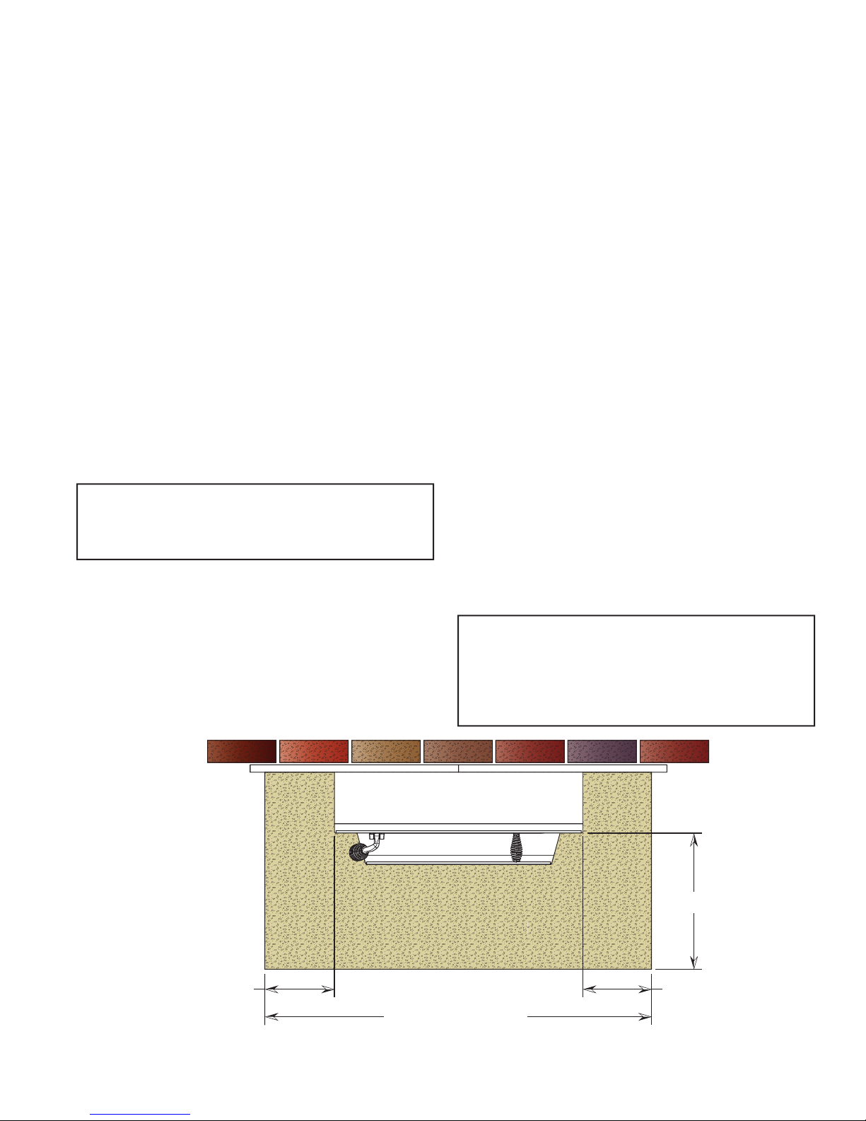
FLOOR PROTECTOR
A solid non-combustible fl oor, concrete or solid masonry,
must extend 6˝ to either side of the body of the appliance
and 12˝ in front of the face of the appliance.
When combustible fl ooring falls within these minimum
dimensions, it must be covered with a listed fl oor protec-
tor meeting the requirements of UL 1618, such as Hy-C
or Imperial Model UL 2840BK or equivalent with 0.84 Rfactor, 1” thick. (Note: to calculate R-value of alternative
materials see Floor Protector Material Calculations at
the back of this manual.) A grouted ceramic fl oor tile that
meets local building codes and the minimum 0.84 R-factor
requirements is considered a durable equivalent.
WARNING: RISK OF FIRE - DO NOT ALLOW COMBUSTIBLE MATERIALS (CARPET, FURNITURE,
FUELS) TO BE PLACED ON OR COVER THE FLOOR
PROTECTOR. ALL COMBUSTIBLE MATERIALS MUST
REMAIN OUTSIDE OF THE MINIMUM CLEARANCE
DIMENSIONS.
US - 6 in. [152mm]
CAN - 8 in. [203mm]
Ussc 5
12 inches [305mm]
FLOOR PROTECTOR
US - 6 in. [152mm]
CAN - 8 in. [203mm]
US - 38 inches [965mm]
CAN - 42 inches [1.06M]
DŝŶŝŵƵŵ&ůŽŽƌWƌŽƚĞĐƚŽƌ^ƉĞĐŝĮĐĂƟŽŶƐ
ASSEMBLY INSTRUCTIONS
TOOLS AND MATERIALS REQUIRED FOR INSTALLATION
TOOLS
• Pencil
• 6 foot Folding Ruler or Measuring Tape
• Tin Snips
• Drill: Hand or Electric
• 1/8” dia. Drill Bit (for sheet metal screws)
• Screwdrivers (Blade and Phillips type)
• 14mm Nut Driver or Ratchet with 14mm Socket
CAUTION: THIS APPLIANCE IS HEAVY. MAKE
SURE THAT YOU HAVE ADEQUATE HELP AND USE
PROPER LIFTING TECHNIQUES WHENEVER MOVING THIS APPLIANCE.
1. Clean the fi replace opening properly disposing of
any ashes in a closed metal container. See Safety
Instructions.
2. Install a 6˝ (152mm) minimum diameter, continuous
stainless steel chimney liner into the existing chimney. The liner must extend to the top of the existing
chimney. Use only listed chimney liners that meet
UL1777 standards. Follow liner manufacturer installation instructions.
MATERIALS
(NOTE: The following items are NOT included with your stove.)
Flooring Protection: as specifi ed herein.
Chimney Liner: Continuous stainless steel chimney liner
(as required)
Stainless Steel Adapter (connects the liner to the fl ue collar)
1/2” Sheet Metal Screws
Furnace Cement (manufacturer recommends Rutland
Code 78 or equivalent)
3. Remove or lock the fi replace damper in the open
position. Note: Masonry or damper plate may be removed to accommodate the chimney liner provided
this does not weaken any structural components of
the existing fi replace or chimney nor reduces protec-
tion of combustible materials required by national
building codes. Consult with your local building or fi re
authority before doing this.
4. Uncrate the appliance, remove all packing materials,
and any items stored in the fi rebox.
5. WARNING: Any fi replace which has had parts re-
moved or modifi ed to accommodate the installation
of this appliance MUST have a warning plate permanently installed in a visible location stating that the
fi replace is unfi t for use with solid fuel. Permanently
attach the warning plate to a visible location in the
fi replace.
6. Position the appliance into the fi replace opening until
the top lip of the air jacket is fl ush with the fi replace
facing.
8. Level the appliance with the adjusting screws at the
rear of the appliance.
9. Connect the chimney liner to the appliance using a
stainless steel adapter and securing with a minimum
of three (3) sheet metal screws. The liner MUST be
attached with the male (or crimped) end of the adapter inside the fl ue collar of the appliance to allow con-
densation and/or creosote to drain back into the fi re-
box.
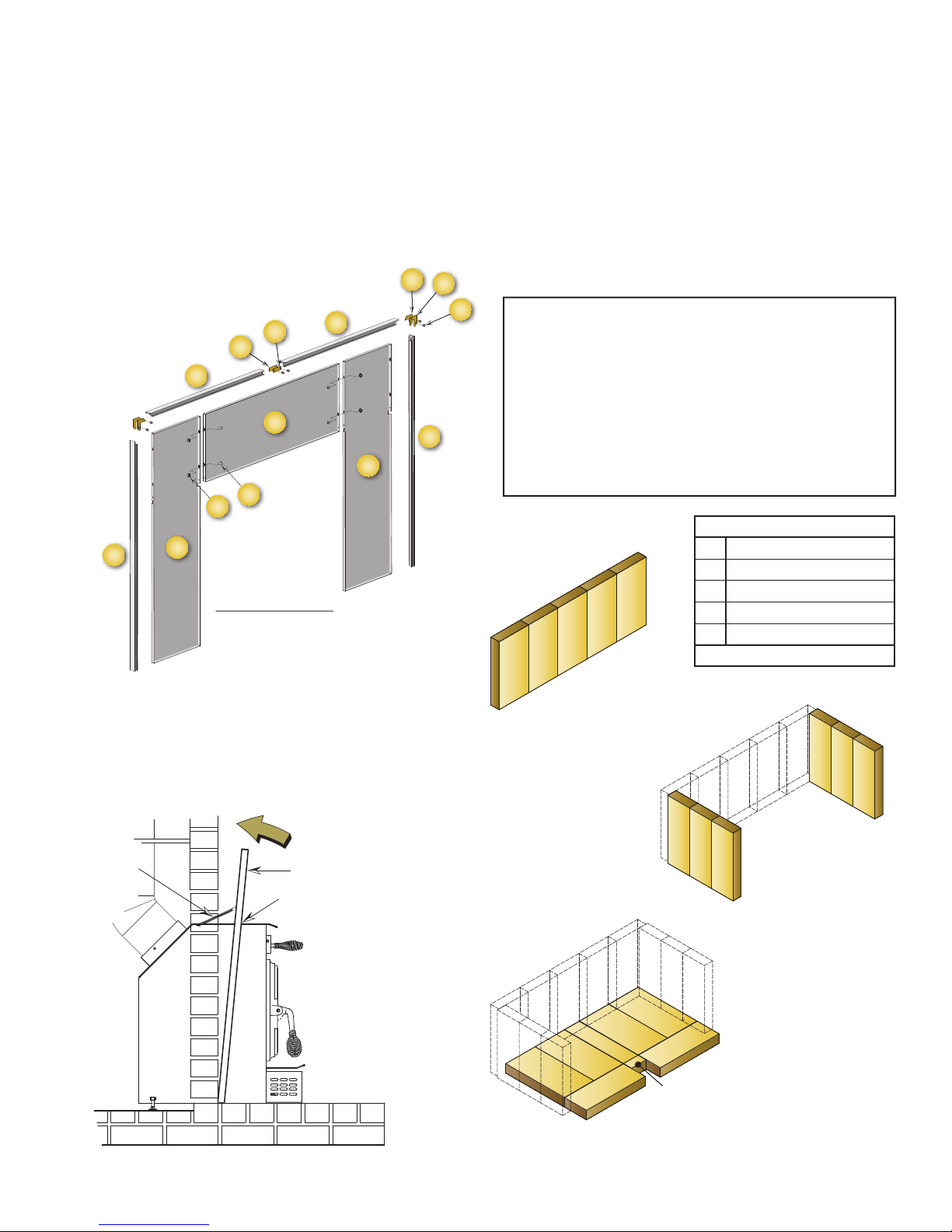
10. Assemble the Surround. Lay pieces face down on
carpet or other soft surface to protect fi nish during
assembly. The Surround consists of two side panels,
a top panel, and a decorative trim frame.
6 Ussc
ASSEMBLY INSTRUCTIONS continued...
11. Bolt the top panel (1) to the side panels (2 and 14) so
the top surfaces are fl ush to one another using items
3 and 4.
12. Assemble the trim frame. The trim consists of a left (6)
and right (5) side piece and a split top piece (left #8,
right #7). These are joined by corner connectors (11-
13) and two straight center connectors (9-10). These
slide into the channel on the back of the frame and
are secured with two set screws (13) in each piece.
11
12
10
9
7
1
4
3
5
13. The trim slides over the surround assembly and is secured at the base of each side with a machine screw.
14. The Surround Assembly is then slid over the appliance. Slots in the two side panels accommodate the
hood at the top of the appliance (fi gure 6).
14
SURROUND ASSEMBLY
VIEW FROM BACK
Figure 6. Surround Installation
8
2
13
6
15. The surround assembly is held in place with two
springs at the top of either corner of the appliance
(fi gure 6).
16.
Connect power cord of blower to grounded receptacle.
17. Firebrick extends the life of your stove and radiates
heat more evenly. If fi rebricks were removed to posi-
tion appliance, replace them before fi ring appliance.
See fi gure 7 for proper orientation and positioning.
Install the back row fi rst, then sides and fi nally install
bottom fi rebricks.
CAUTION: RISK OF FIRE!
• REPLACE FIREBRICKS BEFORE FIRING WOODSTOVE. POSITION FIREBRICKS SO NO GAPS
REMAIN BETWEEN BRICKS.
• NEVER OPERATE THIS APPLIANCE WITH MISSING OR CRACKED FIREBRICK.
• KEEP FURNISHINGS AND OTHER COMBUSTIBLE MATERIALS AWAY FROM THE STOVE AND
OUTSIDE MINIMUM CLEARANCES.
Figure 7a Back Firebrick Arrangement
Five (5) A-Size
A
A
A
A
Firebrick Dimensions: (inches)
A
B
C
D
E
Note: All Firebrick is 1.25” Thick
4.50” x 9.00”
3.33” x 9.00”
3.38” x 9.00”
2.25” x 9.00”
1.25” x 2.25”
A
Figure 7b Side Firebrick Arrangement
Six (6) B-Size
B
B
B
SPRING
SURROUND
Slots in surround
slide of rebox top
Ussc 7
A
A
D
C
A
A
B
C
E
B
B
Figure 7c Bottom Firebrick Arrangement
Four (4) A-Size
Two (2) C-Size
One (1) D-Size
One (1) E-Size
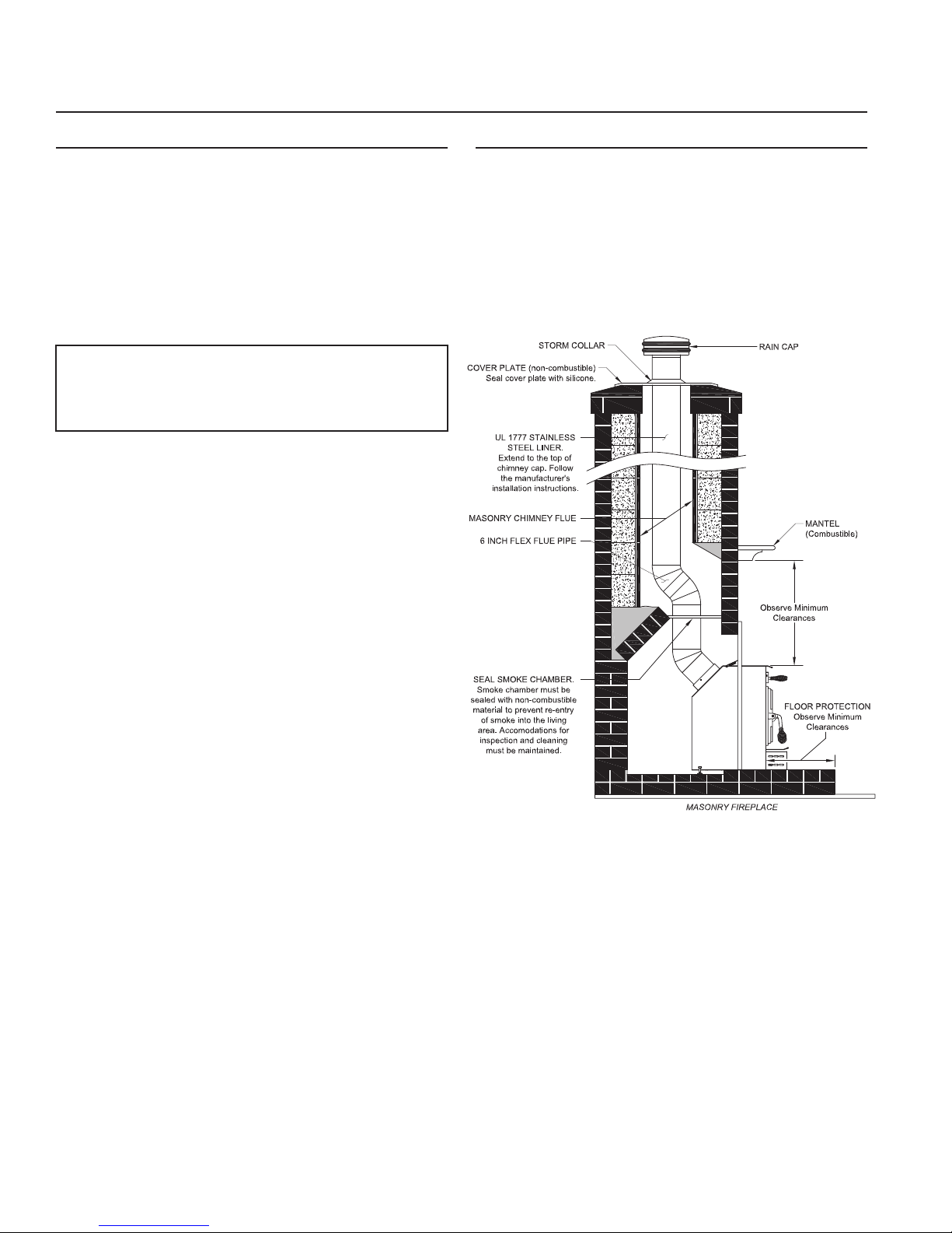
CHIMNEY SPECIFICATIONS
This appliance must be connected to a listed Stainless
Steel Liner, that meets UL1777, which extends from the
collar to the chimney cap according to the specifi cations
listed on the previous pages.
Chimneys perform two functions:
1. As a means of exhausting smoke and fl ue gases which
are the result of fuel combustion.
2. The chimney provides “draft,” which allows oxygen to
be continuously introduced into the appliance, so that
proper combustion is possible. This stove relies on
natural draft to operate.
NOTICE: Always provide a source of fresh air into the
room where the stove is located. Failure to do so may
result in air starvation of other fuel burning appliances and
the possible development of hazardous conditions, fi re,
or death.
Your appliance itself does not create draft. Draft is provided by the chimney. To achieve proper draft your chimney
must meet the three minimum height requirements detailed in fi gure 8. A minimum draft of 0.05 w.c. (measured
in water column) is required for proper drafting to prevent
back puffi ng, smoke spillage, and to maximize perfor-
mance. (Gauges to measure draft are readily available
at stove stores and are economical to rent or purchase.)
Factors such as wind, barometric pressure, trees, terrain
and chimney temperature can have an adverse effect on
the draft. The manufacturer cannot be held responsible
for external factors leading to less than optimal drafting.
Should you have a problem with inadequate draft, you
should contact a licensed heating and cooling contractor
for assistance in solving the problem.
IMPORTANT INSTALLATION POINTS
1. Size chimney fl ue to appliance collar. This stove re-
quires a minimum 6” diameter fl ue.
2. Never connect this unit to a chimney serving another
appliance.
3. The chimney must meet all minimum height requirements.
4. Never use a chimney to ventilate a cellar or basement.
5. Contact your local building authority for approved methods of installation and any necessary permits and/or
inspections.
MASONRY CHIMNEY
Before using an existing masonry chimney, clean the
chimney, inspect the fl ue liner, and make any repairs
needed to be sure it is safe to use. As mentioned previously, this appliance requires a continuous stainless steel
liner from the appliance collar to the chimney cap. Make
repairs before attaching the stove. The connector stove
pipe and fi ttings you will need to connect directly to a ma-
sonry chimney are detailed in the installation instructions.
If the fi replace chimney must go through a combustible
wall before entering the main chimney, consult a qualifi ed
mason or chimney dealer regarding proper materials that
meet all local building and fi re authority codes. The instal-
lation must conform to local building and fi re codes and
latest edition of NFPA 211.
If there is a cleanout opening in the base of the chimney,
close it tightly.
8 Ussc
 Loading...