

Counterline vision aire Operation And Maintenance Manual
vision aire
Operation and Maintenance Manual
freestanding
01-2018
drop-ins
Chilled Displays
part of the idesign range
Counterline Limited
Randles Road
Knowsley Business Park
Merseyside
L34 9HZ
United Kingdom
tel: + 44 (0)151 548 2211
fax: + 44 (0)151 549 2179
service enquiries: servicelog@counterline.co.uk
spare parts enquiries: spareparts@counterline.co.uk
general enquiries: enquiries@counterline.co.uk
web: www. counterline.co.uk
Contents
Page 1 Operation & Maintenance Manual - Vision Chilled Displays
1. OPERATION
1.0 Switching Your Vision Chilled Display Unit On
1.1 Fault When Switching On
1.2 Temperature Control
1.3 Defrost Cycles
1.4 Display Lighting
1.5 Loading With Food
1.6 Chilled Vision Sliding Rear Doors
1.7 Shelf Adjustment
1.8 Installation Of Wall-Sited Chilled Vision Displays
2. CLEANING
2.0 Cleaning Safety Note
2.1 Stainless Steel
2.2 Sliding Rear Doors
2.3 Vision Glass
2.4 Rear Air Guides
2.5 Cleaning Chilled Display Main Tank
2.6 Condensing Unit Finned Coil
2.7 Automatic Evaporating Drip Tray
3. TROUBLE-SHOOTING
3.0 Ice Build-Up On The Coil
3.1 Self Help Guide
Page 3
Page 3
Page 4
Page 4
Page 5
Page 5
Page 5
Page 5-6
Page 7
Page 7
Page 7
Page 7
Page 7-8
Page 9
Page 10
Page 11
Page 12
Page 13
Page 14
Important Information
Page 2 Operation & Maintenance Manual - Vision Chilled Displays
IMPORTANT
Counterline Ltd cannot be held responsible for any accidents or injuries sustained through misuse or improper operation /
maintenance of its products. Please follow our guidelines set out within this handbook for safe working practice. At the design stage, please ensure that the counter understructure can take the weight of the display(s), and that adequate provision
has been made for lifting and positioning the display, to avoid risk of damage or injury.
SAFETY INFORMATION
It is essential that this Vision unit is provided with an electrical supply by a qualied electrician and
installed by a competent person.
The presence of liquids on the display and risk of spillage must be taken into account in designing the electrical
installation around the unit. For additional safety we strongly recommend the tting of a 30ma trip RCD
protection device to the electrical supply. Under no circumstances should electrical cables or points be installed below
the evaporator tray area, as water may overow and cause a hazard.
Vision display units are heavy. We strongly recommend the use of mechanical lifting equipment when handling the units and
positioning them in counters. If no such lifting equipment is available then sufcient personnel must be available to handle
each unit without contravening Company or site Health and Safety Policies.
Before commencing any cleaning or maintenance operation the Vision unit must be isolated from the mains supply by either
removing the supply plug from its socket or switching off at the local isolator.
NB: Switching off using the power switch on the control panel does not fully isolate the unit. These instructions
must be implemented in conjunction with your own Company’s Health and Safety instructions.
WARRANTY
All Counterline products are guaranteed against faulty materials and workmanship for 12 months from the date of invoice
provided that they have been installed, operated, cleaned and maintained in accordance with these instructions.
This guarantee specically excludes damage caused by misuse, scratched or broken glass, quartz heat lights, uorescent
lights and electronic starters.
WARNING
Operation
Page 3 Operation & Maintenance Manual - Vision Chilled Displays
OPERATION
It is essential that you read the instructions carefully and follow all of the cleaning and maintenance
instructions. Failure to do so can result in premature failure that will not be covered by warranty.
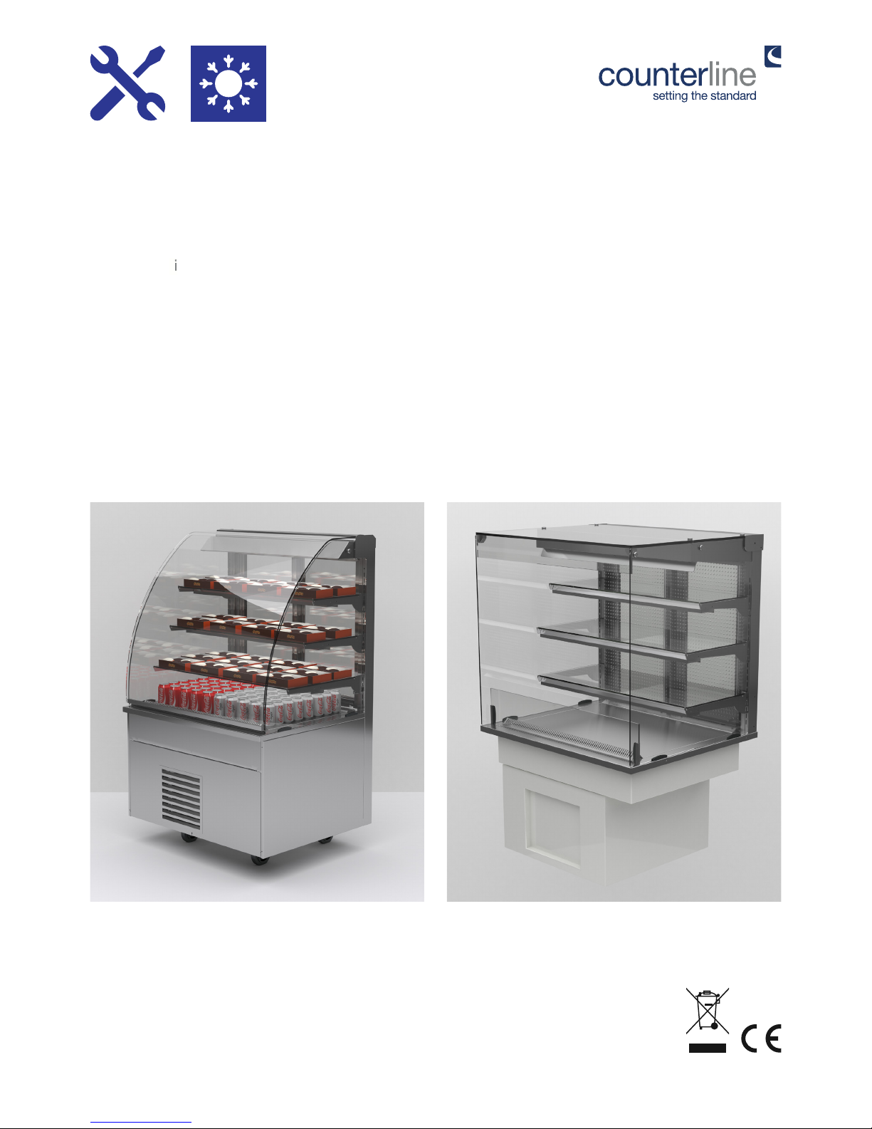
Vision chilled display units are designed to merchandise chilled food maintaining food temperatures by using re-circulated
cold air.
Each shelf level is illuminated by a uorescent strip light for optimum product presentation. Assisted service units have full
height curved glass sneeze screen.
All units have solid glass ends and either xed rear panels or double-glazed doors. The principles of operation and cleaning
are the same for all models whether self help or assisted service, oor mounted or tabletop.
If you have any difculties or need advice please do not hesitate to call our Service department on 0151 548 2211. Make
sure that you have the unit serial number to hand before calling.
Vision units are available as stand-alone units with an integral base or as a drop-in unit with under-slung compressor. The
basic operation and maintenance of these units is the same.
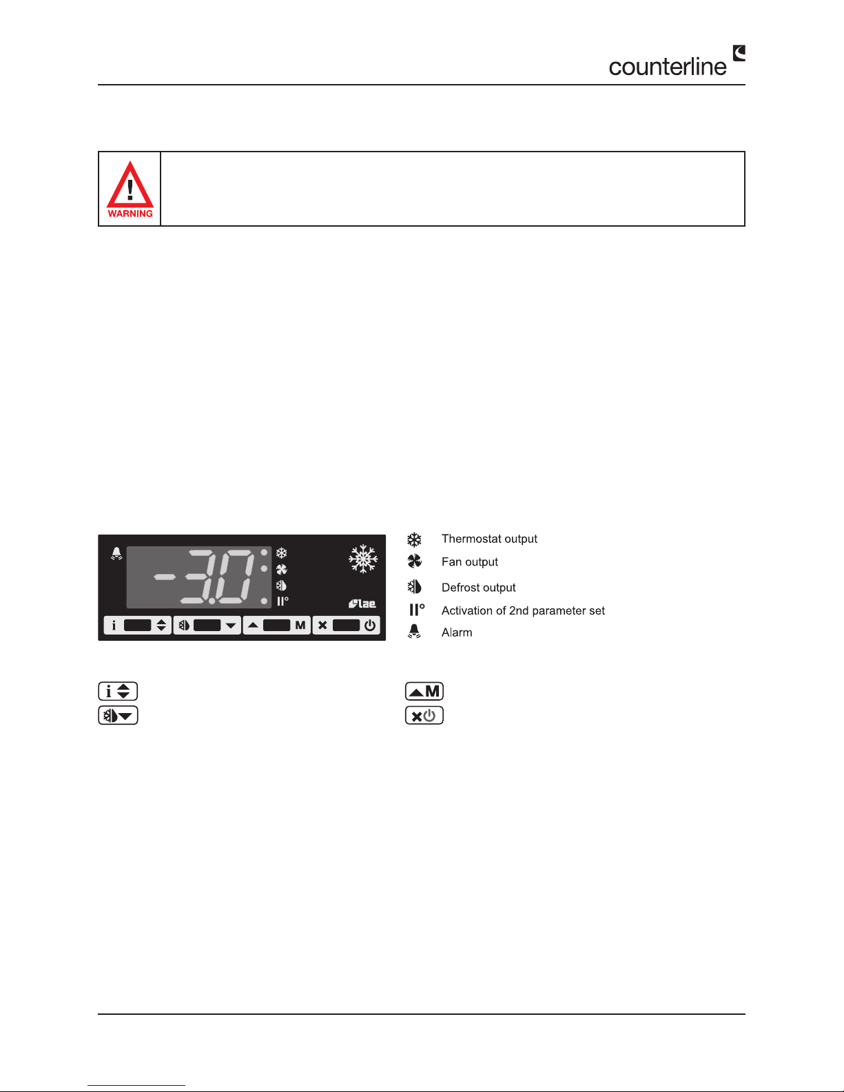
1.0 - SWITCHING YOUR VISION CHILLED DISPLAY UNIT ON
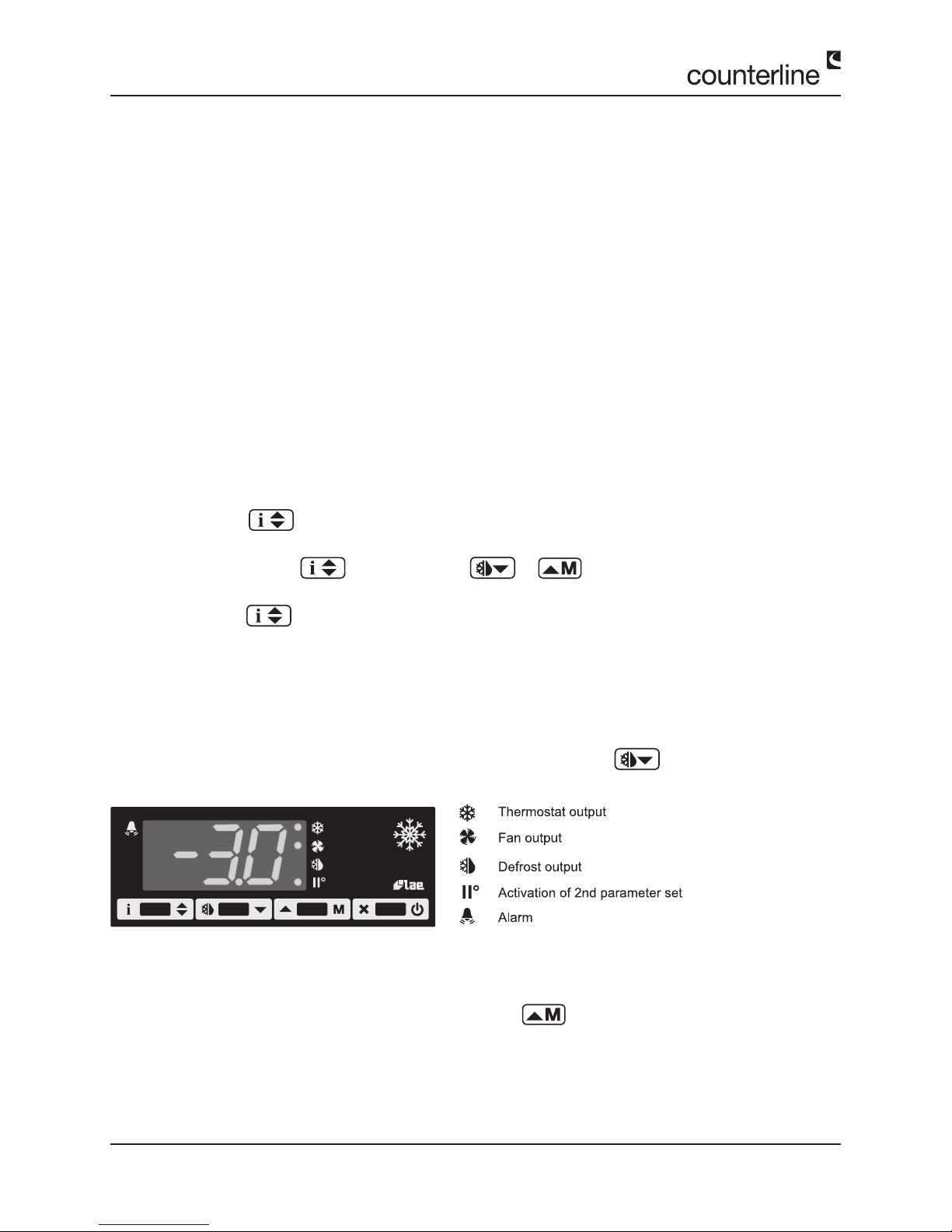
Info / Set point button
Manual defrost / decrease button
Manual activation/ increase button
Stand-by button
INDICATIONSCONTROLLER SET UP
BUTTONS
The digital controller controls both the circulating air temperature and the defrost cycles. It is pre-set to an average air temperature of 0°C, which should maintain food below 5 °C in an ambient temperature below 25 °C.
At this stage there is no need to alter this or any other setting of the digital controller.
1.1 - FAULT ON SWITCHING ON
If after the operation of the main power switch on the control panel it does not illuminate:
1. Check that your Idesign unit has been connected to a mains supply by your installer, and that this supply is live.
2. Isolate the unit and check the supply fuse.
3. Take care to ensure that you replace a fuse with one of the same rating. If you can nd no fault call your installer for
help.
Page 4 Operation & Maintenance Manual - Vision Chilled Displays
Operation
1.2 - TEMPERATURE CONTROL
In the Vision system of chilled food display, the food temperature is maintained at or below 5 °C by a stream of re-circulated
cold air.
The air blows across the display deck, coming from grilles or holes on the operators side and returning to the fans via a
grille at the customer’s side.
It is essential that neither of these grilles be obstructed in any way, as the airow and efciency of the refrigeration
system will be restricted.
The top of the displayed food must also be 50mm lower than the edge of the well or the glass surround if tted. This system
is very effective in a draught free environment with an ambient temperature of no more than 25°C.
Where ambient temperatures above 25 °C or draughty conditions exist, the display will not maintain food temperatures at
required levels.
Your digital controller will be pre set at the factory to give a food display temperature of 2/5°C in typical operating conditions. Under normal conditions the controller displays the actual temperature of the cold air around the food.
If you need to alter the pre set temperature proceed as follows:
Gantry digital controller (See diagram below)
1. Press Button for a least half a second, to display the set point value.
2. By keeping the button pressed, use button or to set the desired value.
3. When button is released, the new value is stored.
It is important that only small adjustments of say 1 or 2°C are made to the controller at any one time. The unit should then
be allowed to operate for at least one normal working day and food core temperatures monitored before any further adjustments are made.
1.3 - DEFROST CYCLES
On a gantry controller, if required, a manual defrost can be started by pressing button for ve seconds.
1.4 - DISPLAY LIGHTING
On a gantry control display lights are switched on by pressing button with the light symbol on it. If the lights do not
come on, consult the self help page on section 3 of this manual.
 Loading...