

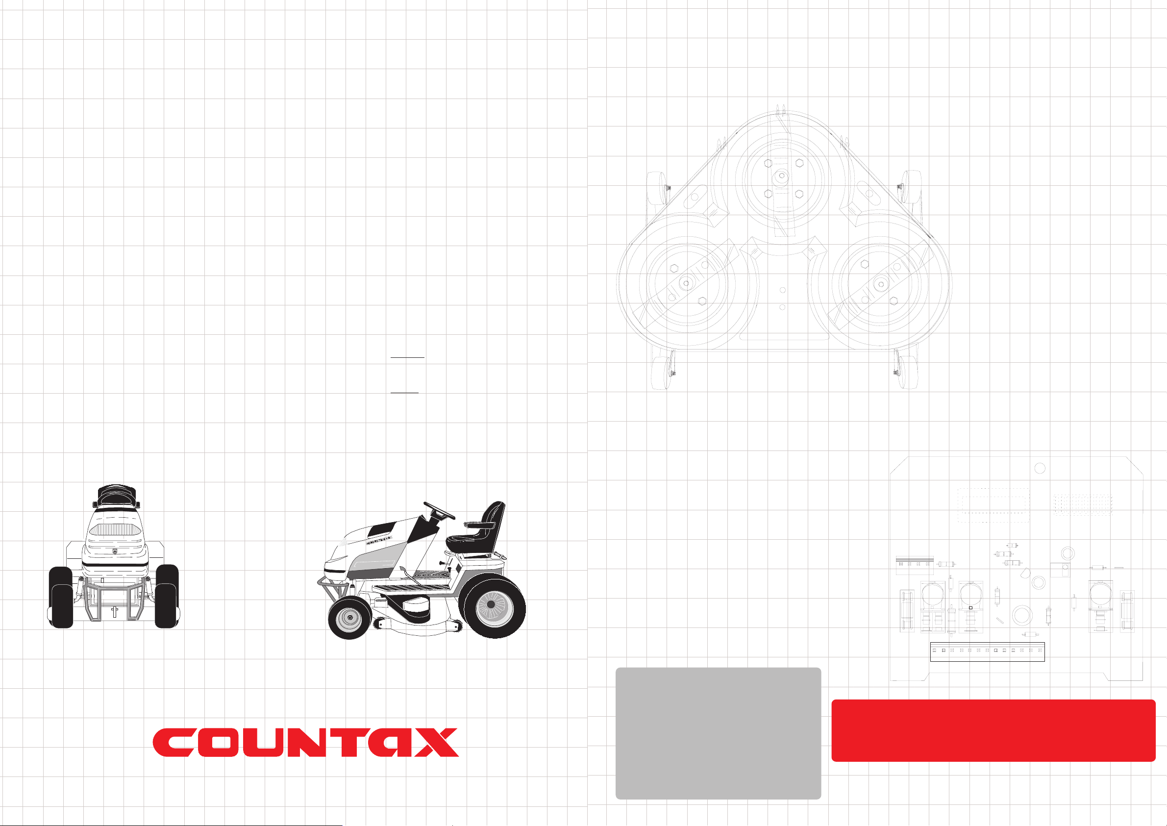
OPERATORS MANUAL
SPECIFICATION SUMMARY
Engine Lubricant
1.7 litres
Recommended SAE30 or 10W - 30 high quality
detergent oil classified for service; SG, SF, SE.
Read and follow the instructions in the engine
manufacturer’s handbook.
Fuel Tank Capacity
7 litres (1.5 gallons)
Transmission
Tuff Torq Heavy Duty Hydrostatic K62,
infinitely variable speed control with
Diff lock. Sealed for life lubrication.
Dimensions (approx.)
Length 1.96m (78”)
Inc Sweeper 3.07m (121”)
Height 1.17m (46”)
Width 1.3m (51”) (excluding Deck)
Weight
A20/50 325Kg
Sweeper 62Kgs
Net 36Kgs
PGC Capacity
390 litres
Forward Speeds
0-7mph
Countax Limited, Countax House, Great Haseley, Oxford OX44 7PF
Tel: (01844) 278800 Fax: (01844) 278792
Email: email@countax.com Website:www.countax.com
®
All figures are approximate. We reserve the right to change specification and price without notice E&OE
© copyright 2002 Countax Limited
Turning Radius
125cm
Recommended Tyre Pressure
FRONT
0.8-1.1KgF/cm (12-16lb PSI)
REAR
0.43-0.7KgF/cm (6*-10lb*PSI)
* Pressure recommended for maximum grip.
NEVER INFLATE ABOVE THE
MAXIMUM PRESSURE SHOWN
A20-50
Page 2 Page 27
Notes:Safety Instructions
CERTIFICATE OF CONFORMITY
EC Declaration of Conformity
I, the undersigned A. Bennett of Countax Limited Great Haseley Oxford
OX44 7PF declare that the Lawnmowers described below :
Model A20/ 50
Power (kW) 14.9
Maximum blade rotation (rpm) 3100
Engine Manufacturer Briggs & Stratton
Engine Type 4 stroke Petrol
Guaranteed Maximum Sound Power level 105dB(A)
Max. Vibration m/s_ (Hands) 2.05
Max. Vibration m/s_ (Seat) 0.53
Cutting Device Cutter
Cutting Device Width 127cm
Complies to the provision of the directive 89/392/EEC amended by
98/37/EC and the regulations transposing it into national law.
Complies with the provisions of "noise emission in the environment by
equipment for use outdoors" directive 2000/14/CE and the regulations
transposing it into national law Complies with the provisions of "electromagnetic compatibility" 89/336/EEC directives and the regulations transposing it into national law.
Tested at : Oxford, England
Signed:
A.Bennett 1/2/02
MANDATORY SAFETY INSTRUCTIONS FOR
THE OPERATION OF GARDEN TRACTORS
1. Read the instructions carefully. Be familiar with the controls and
the use of equipment.
2. Never allow children or people unfamiliar with these instructions
to use the mower.
3. Never mow while people, especially children, or pets are nearby.
4. The operator or user is responsible for accidents or hazards
occurring to other people or their property.
5. Do not carry passengers.
6. All drivers should seek to obtain professional and practical
instruction. Such instruction should emphasise:
• The need for care and concentration when working with this
machine.
• Control of a Tractor sliding on a slope will not be regained by the
application of the brake.
The main reasons for loss of control are:
• Insufficient wheel grip.
• Driving too fast.
• Inadequate braking.
• Incorrect load distribution.
1. Check that the machine complies with all applicable
regulations, including those in force when used on the
public highway.
2. When mowing always wear substantial footwear and long
trousers. Do not operate when barefoot or with open toe
sandals.
3. Warning – petrol is highly flammable:
• Store fuel in containers specifically designed for this
purpose.
• Refuel outdoors only and do not smoke when refuelling.
• Add fuel before starting the engine. Never remove the cap
from the fuel tank or add petrol while engine is running or
when engine is hot.
• If petrol is spilled, do not attempt to start engine but move
the machine away from area of spillage and avoid creating a
source of ignition until petrol vapours have dissipated.
• Replace the fuel tank cap securely.
TRAINING
PREPARATION
Contents Summary:
Safety Instructions -Page 2 and 3
Controls and Indicators - Dashboard -Page 4
Controls -Page 5 and 6
Mulch Deck -Page 7
Rear Discharge Deck -Page 8
Cutter Deck Removal -Page 9
Cutter Deck - Check List -Page 10
Deck Levels - Front to Back -Page 11
Cutter Levelling Side to Side -Page 12
Cutter - Drive Belt -Page 13
Powered Collector -Page 14
CollectorAdjustments -Page 15
Collector Drive Belts -Page 16
Collector Brush -Page 17
Tyres - Check List -Page 18
Tyres - Removal of Wheels -Page 19
Engine - Oil -Page 20
Engine - General Maintenance -Page 21
Electrical -Page 22
A20/50 Wiring Diagram -Page 23
READ THE INSTRUCTION MANUAL BEFORE USING
THE GARDEN TRACTOR AND ENSURE THE
OPERATORS STUDY IT FOR THEIR OWN SAFETY.
THE FOLLOWING PRECAUTIONS ARE OUTLINED
TO HELP PREVENT ACCIDENTS. A CAREFUL
OPERATOR WHO USES COMMON SENSE IS THE
SAFEST OPERATOR.
THESE SAFETY PRECAUTIONS ARE IN ADDITION
TO THOSE IN THE INSTRUCTION MANUAL.
THIS SYMBOL MEANS BE ALERT
CAUTION

Page 26 Page 3
Safety InstructionsNotes:
4. Replace faulty silencers.
5. Before using always inspect to see that the blades, bolts and
cutter assembly are not worn or damaged.
6. Check the condition of the tyres and ensure that they are
inflated to the correct pressure (refer to the specifications).
This is particularly important if the machine is to be taken
on the public highway.
7. Check the mower is in good working order, paying
particular attention to brakes and steering.
8. Check that all linkages, connections, and pivot nuts are
secure and that the wheel nuts are torqued correctly.
1. Do not operate the engine in a confined space where
dangerous fumes can collect.
2. Mow only in daylight or in good artificial light.
3. Before starting the engine, disengage blade and attachment
drives and shift into neutral.
4. Take care on slopes of more than 10º incline or decline
(Maximum safe operation is at 15º).
5. Remember that there is no such thing as a ‘safe’slope.
Travel on grass slopes requires particular care to guard
against overturning:
• Do not stop or start suddenly when going up or downhill.
• Engage clutch slowly. Always keep machine in gear,
especially when travelling downhill.
• Machine speed should be kept low on slopes and in tight
turns.
• Stay alert for humps and hollows and other hidden hazards.
• Avoid mowing across the face of the slope.
6. Watch out for traffic when crossing or near roadways.
7. Stop the blades rotating before crossing surfaces other than
grass.
8. When using the machine, never direct discharge of material
toward bystanders or allow anyone near the machine while
in operation.
9. Never operate the mower with defective guards, shields or
without safety protective devices in place and in good
working order.
10.Do not change governor settings to increase the revs of the
engine. Operating an engine at excessive speed increases
the risk of injury.
11.Before leaving the operators position:
• Disengage the drive to the cutter blades and attachments
and lower the attachments.
• Change to neutral and set the parking brake.
• Stop the engine and remove the ignition key.
12 .Disengage drive to attachments, stop the engine and
disconnect the spark plug lead or remove ignition key
before:
• Clearing blockages.
• Checking, cleaning or working on the mower.
• Refuelling.
• Removing the grass catcher.
• After striking a foreign object. (Inspect the mower for
damage and make repairs before restarting the Tractor).
• If the machine starts to vibrate abnormally check immediately
and call dealer if necessary.
13.Disengage drive to attachments when transporting or not in use.
14.Reduce the throttle setting during engine run-out.
15.Never work on the mower when the engine is running.
1. Check that all nuts, bolts, and screws are tight to be sure the
equipment is in safe working condition.
2. Never store the equipment with petrol in the tank inside a
building where fumes may reach open flame or spark.
3. Allow the engine to cool before storing in any enclosure.
4. To reduce the risk of fire keep the engine, silencer and battery
compartment free of grass, leaves, petrol or excessive grease.
5. Check the grass catcher frequently for wear and tear or
deterioration.
6. Replace worn or damaged parts for safety.
7. If the tank has to be drained, this should be done outdoors.
8. Be careful during adjustments of the machine to prevent
entrapment of the fingers between moving blades and fixed parts
of the machine.
9. Do not use steam cleaners or high pressure washers directly
towards bearings or electrical components (Countax do not
recommend the use of these power cleaners).
SUPPLEMENTARY INSTRUCTIONS FOR USE
OF COUNTAX A20/50 TRACTOR
1. Use good sense at all times and, to ensure this Tractor is safe and
serviceable, fit only original manufacturers’ supplied spares.
2. When inspecting the area to be cut, note also the position of any
stumps, manhole covers, bumps and depressions and avoid them
to prevent damaging the blade.
3. We recommend the use of standard UNLEADED fuel and that
you ensure the fuel tank is full before you start the machine.
4. Always disconnect both battery terminals before attempting any
work in the engine compartment.
5. Do not leave the Tractor unattended and running.
6. Do not put hands near moving belts or the Power Take-Off pulley
while it is rotating.
OPERATION
MAINTENANCE AND STORAGE
Page 4 Page 25
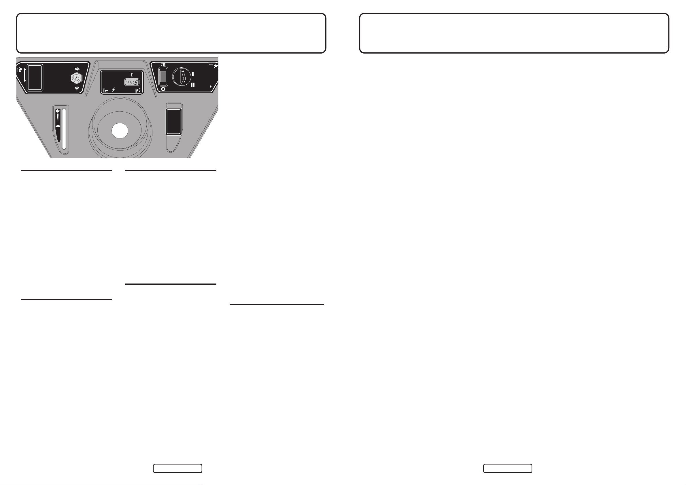
Notes:Controls and Indicators - Dashboard
IGNITION
The ‘Key Start’controls both the ignition
and the starter. Insert the key and turn to
the 1st position, the dashlights will come
on (check that all is ready to start), then
turn further to activate the starter. Release
when engine starts. To stop, turn the key
to the left (having first switched off both
cutter and PTO).
IT IS ALWAYS GOOD PRACTICE
TO REMOVE THE KEYAND KEEP
IT SAFE.
As with a car, it is important to prevent
unauthorised use by children who could
injure themselves.
CHOKE
An independent choke is fitted to the
A20/50. This choke should be used in
combination with a fast throttle setting to
start a cold engine. Cancel as soon as
possible. Do not use choke on a warm
engine.
CUTER ON/OFF SWITCH
The cutter switch controls the
Electromagnetic Blade Clutch. It works
like a light switch (but in reverse) – UP
for ON and DOWN for OFF. Although it
always returns to the central position and
the cutter deck will automatically be
turned off when the engine is switched
off, it is not good practice to rely on this.
The cutter deck should always be
switched
OFF as soon as you have
finished cutting and certainly BEFORE
stopping the engine or getting off the
Tractor.
THROTTLE
The lever is pushed forward and up for
FAST, back and down for SLOW. A
cold engine is started on the
FAST
setting with choke, a warm one on the
FAST setting. The Choke setting should
be cancelled as soon as possible and the
engine operated on
FAST setting at all
times.
HEADLIGHT SWITCH
The headlights are turned ON by switching
the rocker switch on. The headlights will
not operate when the ignition is
OFF. Turn
the headlights OFF before starting or
stopping.
O

Page 24 Page 5
Controls - Forward/ReverseHE Wiring Diagram

Page 6 Page 23
Wiring DiagramControls - Levers
POWER-TAKEOFF (PTO)
Push the lever down and to the left to engage the pto, to disengage
push the lever down and lift to the right.
ELECTRIC LIFTS
The cutting height is adjusted by rotating the ‘dial-a-height’switch
anti-clockwise to lower the deck and clockwise to raise the deck.
The indicated heights (1-lowest to 10-highest) are shown for
guidance purposes only. To get the best from this refinement use it
to continuously adjust cutting height to suit ground and grass
conditions. Do not make downward adjustments on the move until
you are familiar with this height control, to avoid scalping.
Raising the Auxiliary Lift is achieved by pressing the switch (
B) to
the left of the dashboard – UP to raise, DOWN to lower (fig 3).
PGC NET EMPTY SWITCH
A third switch is fitted to those Tractors with a Powered Grass
Collector. This switch empties the collector net via an electric
actuator mechanism that lifts the grass box and pushes out the
bottom pan, fully emptying the collector contents. Press the switch
UP to open and DOWN to close the net (fig 5).
SEAT ADJUSTMENT
The seat on the A20/50 is adjustable forwards and rearwards to suit
the operator. Simply lift the seat latch at the front of the seat (fig 4)
and slide the seat forwards or backwards to suit. Always ensure the
seat is latched back into position before driving off.
(A) Dial-
a-height
Switch
(B)Auxiliary
Lift Switch
fig 1
fig 2
fig 3
fig 4
fig 5
PGC Net Empty
Switch
Press UP to empty
and DOWN to Close
Electric ClutcElectric Clutch
Switc Switch
Light SwitcLight Switch
LoomLoom
ConnectorConnector
RedRed
LoomLoom
ConnectorConnector
Light LoomLight Loom
ConnectorConnector
Brake SwitcBrake Switch
Fuel SolenoidFuel Solenoid
Soc Socketket
RegulatorRegulator
StarStarterter
MotorMotor
Seat SwitcSeat Switch
P.T.O.
SocSocketket
(Red / Blue)(Red / Blue)
Ignition Cut OutIgnition Cut Out
(Bolt on Connector)(Bolt on Connector)
Ignition Cut OutIgnition Cut Out
(Female Spade Connector)(Female Spade Connector)
Connector For H.E.Connector For H.E.
EarEarth Connectorth Connector
For H.E. For H.E.
IgnitionIgnition
SwitcSwitch
15A15A20A20A
20A20A
SolenoidSolenoid
Electric ClutcElectric Clutch
BatterBattery
EngineEngine
1
2
4
5
TRATRACTCTOR OR WIRING DIAWIRING DIAGRAMGRAM
Ignition SocIgnition Socketket
10A10A
10A10A
12 Red / 12 Red / Yellow w
1 WhiteWhite
2 Red / Blue 2 Red / Blue
3 Br 3 Brownwn
4 Gre4 Grey
5 Red / Blue
6 White / RedWhite / Red
7 Black
8 Purple
9 Yellow
10 Green10 Green
11 Orang11 Orange
13 Blue13 Blue
Orange
Purple
Black
Red
Red /
Blue
+
-
3
6
PTO
IMPORTANT - READ SAFETY INSTRUCTIONS BEFORE OPERATING THIS MACHINE
MULCHING
For Best results;
- Do not reduce the height of the grass by more than 1/3 in a single pass
- Mow often - short clippings of 25mm (1") or less decompose more quickly
- If possible, avoid cutting in the wet
- Always cut with the engine at full running speed
- If an unsightly residue is present - increase cutting height
- Vary mowing pattern from cut to cut
- Always keep the underside of the deck clean to permit good grass flow
- Always ensure that blades are sharp and in good condition
VIBRATION TESTED TO THE FOLLOWING STANDARDS
BS 6842:1987, DD ENV 25349:1993, SI 1992:3073, BS6841:1987
O
O
15 MAX
15 MAX
EXERCISE CAUTION WHEN CUTTING
ON SLOPES
O

Page 22 Page 7
Mulch DeckElectrical
MULCH MOWING
Mulching can save time, avoids gathering
piles of rotting cuttings and feeds your
lawn. It is however necessary to observe
certain rules to mulch mow successfully:
• Reduce the height of the grass by no
more than 1/3rd its height in each pass.
If the grass has grown long make
several passes to achieve the cut height
you require.
• Always cut with the throttle set to
FAST – mulching needs the full
running speed of the engine.
• Mow often, particularly in Spring and
early Summer. Short clippings of
25mm (1") or less decompose more
quickly.
• If possible avoid cutting in the wet.
• If an unsightly residue of cuttings is
being left – increase the cutting height.
• Vary the mowing pattern from cut to
cut.
• Always keep the underside of the
cutting deck clean to ensure good grass
flow.
• Always check that the blades are sharp
and in good condition – but do not
attempt to sharpen or replace them
yourself. New Countax blades are not
expensive and it is good practice to ask
your dealer to change them regularly.
There are five 20 Amp fuses on the
A20/50 Tractor.
1. 20Amp (
yellow) for charging circuit.
2. 20Amp (
yellow), ignition, safety
switches.
3. 20Amp (yellow) electric lift for Cutter
Deck and Auxiliary lift.
4.20Amp (
yellow) located left-hand side
of the console is for net emptying circuit.
To check - remove fuse and check small
window, there should be an unbroken
metal strip bridging the gap (fig 4).
Note - If No.2 20Amp fuse blows when
the ignition key is turned this means there
is a short between the red and blue
coloured wire and the body of the Tractor.
The usual places to investigate are:
• The electrical PTO and socket.
• Seat switch wires (fig 3).
If fuses blow after these have been
checked, call your dealer.
PRINTED CIRCUIT BOARD
FUSES
There are 2 10Amp Blade fuses on the
circuit board (fig 5) which can be reached
by removing the cover (fig 1). These two
fuses control the lights and the
Electromagnetic Blade Clutch. If the
problem is not a fuse and you cannot see
any loose connections - call your dealer.
ELECTROMAGNETIC BLADE
CLUTCH
If the blade clutch disengages without
being switched off these are the possible
causes:
• You have got off the seat - the safety
switch will disengage the cutter.
• The battery has lost charge and will no
longer hold the clutch in operation.
• Fuse blown on Printed Circuit Board -
see above.
• Faulty Safety Switch or break in wire -
see your dealer.
fig 1
fig 2
fig 4
fig 5
fig 3
Fuse Box
PCB located
under the
Dashboard
Possible
source of short
- Seat Switch
Printed Circuit Board
Mulch Deck
Blades
Mulch Deck
Pulley Arrangement
The Mulch Deck
Process
Hour Meter
(Located on the
other side of the
PCB)
10 Amp Blade
Fuse for
Electric Clutch
10 Amp Blade
Fuse for Lights
1
2
3
20
20
20Amp
( yellow )
20
20
20Amp
( yellow )
20
20
20Amp
( yellow )

Page 8 Page 21
Engine - General MaintenanceRear Discharge Deck
fig 1
Specified Belts and Blades
Engine/Deck Belt - B56 Dayco Super II - Pt No. 22940100 (IBS)
Engine/Deck Belt - B57 Dayco Super II - Pt No. 22871200 (MULCH)
Deck Internal Drive Belt (Mulcher) - BB112 Pt No. 228000900
(Rear Discharge) - Dayco Super II BB155 Pt No. 22950200
Mulcher Blades x3 Pt No. - 216938100
IBS RH Blade Pt No. 169381300
IBS LH Blade Pt No. 169381400
IBS Front Blade Pt No. 1692000
PGC Drive Belt Super II A49 - Pt No. 228001200
PTO Drive Belt - Dayco Super II A92 - Pt No. 22950100
Transmission Drive Belts - A92 Dayco Super II - Pt No. 22950100
N.B. Only use specified Belts and Blades - Never accept a substitute!
Routing for IBS internal deck drive belt
VANGUARD
Page 20 Page 9
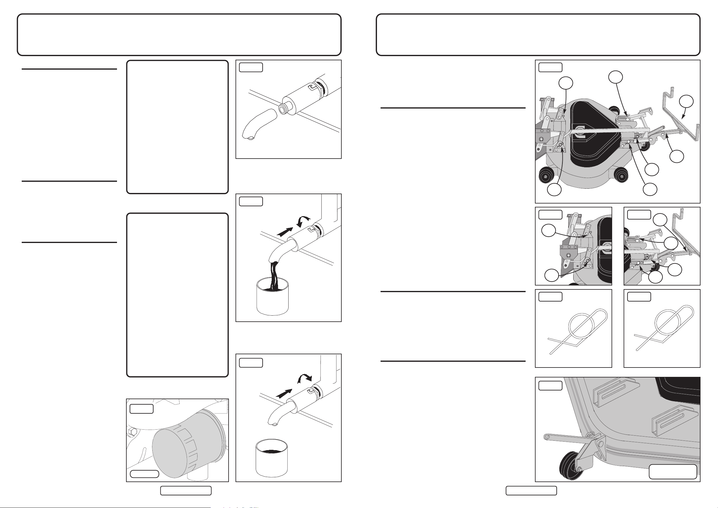
Cutter Deck Removal
(Mulch/Rear Discharge Deck)
Engine - Oil
The Rear Discharge Deck is used in conjunction with the
PGC. It ejects the grass rearwards after cutting for the
Powered Grass Collector to collect. Either the Mulch Deck or
the Rear Discharge Deck can be fitted to the A20/50 using the
following instructions:
REMOVAL OF CUTTER DECK
The cutter deck can be quickly removed for servicing or
cleaning or to give greater clearance when driving or towing
over uneven ground.
Follow this sequence:
1. Put cutter to lowest position.
2. De-tension the Cutter Drive Belt with the lever under the
left (nearside) running board.
3. Remove the 3 securing pins from the front of the deck
(fig 3 – A, B and C) by pulling out the spring clips.
4. Remove pin G and remove deck tension bar.
5. Remove fifth anti-scalp wheel (fig 6)
6. Remove the 2 securing pins from the back of the deck
(fig 2 – D and E).
7. Slip the Cutter Drive Belt off the Engine Pulley.
8. Slide the deck out.
9. If you are going to use the Tractor without the deck, remove
the Securing Bar (F).
WHEN REPLACING THE CUTTER DECK, RE-TENSION
THE BELT WITH THE LEVER UNDER THE RUNNING
BOARD. Then check the belt tension (see page 13).
TO CLEAN CUTTER DECK
Remove the deck as instructed, stand it on its side and hose off
accumulated cuttings. This may be necessary routinely to
prevent build-up of cuttings, particularly at the beginning of
the season when the grass is lush and wet. Thoroughly wash
the underside of the cutter deck as regularly as possible.
ENGINE TO CUTTER DRIVE BELT
REPLACEMENT
Follow this sequence:
1. Pull the Belt Tension Lever (page 13 fig 1) forward.
2. Lower the Cutter Deck to the lowest position.
3. Remove the belt from the forward Electric Clutch Pulley –
it will slip off.
4. Remove the Cover of the Cutter Deck Pulley Housing –
loosen and remove the 1/4" UNF nut and bolt using two
7/16" spanner/sockets – then slide (tap) the cover off.
5. Remove the belt from the Cutter Deck Pulley – you may
have to ease it off by rotating the pulley.
6. Now replace with the CORRECT BELT (see previous page)
by reversing this procedure, taking care to fit the belt
into the ‘V’grooves.
7. Pull back the Belt Tension Lever so the belt is tensioned.
Now check and adjust belt tension as detailed on page 13.
fig 1
fig 2
fig 4
fig 3
fig 5
SECUREDUNSECURED
C
B
A
F
G
D
E
D
E
F
C
B
A
fig 6
OIL DRAINING
NOTE: OIL SHOULD BE CHANGED
WITHOUT FAILAFTER THE FIRST
FIVE HOURS OF RUNNING.
The A20/50 Tractor has an oil drain
adaptor (fig 1) located on the right hand
(off side) of the engine. This is like a
bayonet light fitting, which you push in
and turn anti-clockwise to release. A
short length of clear hose is supplied in
the toolkit that fits on this adaptor so that
waste oil can be poured into a can or
bottle.
BEFORE DRAINING
* Start up the engine and allow to idle
until it is warm (about five minutes).
* Switch off the engine, lift open the
bonnet, and unscrew the oil
cap/dipstick.
TO DRAIN
* Locate the Oil Drain (fig 1).
* Remove the Yellow Dust Cap.
* Fit the short length of hose supplied
over the nozzle of the adaptor (see fig
2) and direct the other end into a
container large enough to take 2 litres
of waste oil.
* Press the adaptor in; turn anti-
clockwise to lock (fig 3). Remove hose
and store for next use. Replace Yellow
Dust Cap.
* Refill with recommended oil (SAE30
detergent oil classified for service SG, SF, SE) to engine manufacturer’s
instruction.
DO NOT OVERFILL
The use of lubricants that are not
recommended may lead to excessive
wear or damage - and this will NOT be
covered by warranty.
ALWAYS READ AND FOLLOW THE
ENGINE MANUFACTURER’S
INSTRUCTIONS ON ALL MATTERS
RELATING TO USE AND
MAINTENANCE. OBSERVING THE
OIL CHANGE INTERVALS WILL
GREATLY ENHANCE THE SERVICE
LIFE OF YOUR ENGINE!
N.B.
The information contained in
the following pages is given
on the understanding that
Countax accepts no
responsibility for work
carried out by a customer or
for any damage thus caused
whether or not the service
instructions have been
misunderstood. To be
absolutely sure that your
warranty terms are not
breached, service work
should only be carried out by
a Countax dealer.
Before carrying out any
repair or servicing
Ensure that the Tractor is on
a firm level surface.
Apply the handbrake.
Disconnect the battery.
Extinguish all naked flames.
Oil Filter
fig 4
fig 1
fig 2
fig 3
Removal of Fifth
Anti-scalp wheel

Page 10 Page 19
Tyres - Removal of WheelsCutter Deck - Check List
CUTTER FAILS TO START OR CUTS OUT
WHEN SWITCHED ON
Check:
* Are you on the Tractor? – Unless you sit on the seat the safety
switch cuts out the Cutter Deck.
* Is the battery low? – The Clutch Engage Switch will only
operate if the battery is well charged.
* Does the 10Amp-blade fuse on the printed circuit board need
replacing? (see page 22)
* That either the cutter switch or the safety switch on the seat is not
faulty – if so, call your dealer.
UNEVEN CUT (CUTS SHORTER ONE SIDE
THAN THE OTHER)
Check:
* That the tyres are all inflated to the correct pressure (see back
page).
* That the front axle is pivoting freely.
* That the deck suspension brackets are moving freely and not
hitching up.
* That the side to side deck level adjustment is correct
(see page 12).
CUT IS UNEVEN OR UNTIDY IN ONE OR MORE
SECTORS
Check:
* That Cutter Deck is levelled correctly front to back (see page 11).
* That one or more of the blades are not worn or damaged – if so,
call your dealer.
THE CUTTER SEEMS TO LOSE POWER AND
THE BELT SLIPS AND OVERHEATS
Check:
* That the Tensioner Rod is correctly applied.
* That the Cutter Belt Tension is correct (page 13).
* That the Cutter Deck is not clogged with wet cuttings.
* That the Cutter Drive Belt is not worn.
We do not recommend that customers attempt to
change cutting blades themselves - Remember
that it is never worthwhile to have blades
reground - It is cheaper and better to replace.
Re-grinding is likely to affect the hardening of the
blade and its balance.

Page 18 Page 11
Deck Levels - Front to BackTyres - Check List
The Cutter Deck should be set so that it is parallel to the
surface it is cutting with a maximum variation from side to
side, or front to back of 3mm. Check this by placing the
Tractor on a hard level surface and measuring the clearance
heights front to back and side to side with a steel ruler or tape
with the Cutter set one adjustment up from its lowest position.
If the Cutter Deck seems to require levelling first check these
other possible causes:
1. Are the tyres inflated correctly all round – if not, inflate to
the correct pressures.
2. Are the Cutter Deck Hanger Brackets (fig 2) moving
freely or are they hitching up. To check this lift the cutter
deck to its highest position and lift and rock it, watching to
ensure that the brackets move freely – if not clean and
grease.
3. Is the Front Axle pivoting freely? – If not, clean and oil.
4. Is there any impact damage that has bent or distorted the
Deck or Suspension Brackets (a matter for your dealer).
If the Deck is still uneven: -
LEVELLING FRONT TO BACK
(You need two people for this operation – one to lift the Deck
while the other removes or relocates the Trunnion)
1. Ensure that the Anti-Scalp Wheels are all adjusted in the
same hole – if not, rectify (fig 3).
2. Lower the Cutter Deck to a position one above the lowest
setting – check levels with the ruler or tape.
3. Now locate the front to back Adjustment Rod to the right
(offside) of the cutter. At the rear end of this Rod, near the
rear offside wheel, you will find the Trunnion (fig 2) that
links the rod to the Deck Hanger Bracket. Both the
Trunnion and the Rod are threaded and adjustment is
achieved by rotating the Trunnion to ‘in effect’shorten or
lengthen the Rod.
4. To free the Trunnion use a 9/16" spanner or socket to
remove the 3/8" Nyloc nut and washer and push it free.
5. Rotate the Trunnion to advance it up the Rod to lift the back
of the Deck. Rotate it the other way to lift the front.
Adjustment is rapid so try one or two turns and relocate the
Trunnion Bracket and secure – then check the effect. Repeat
and re-check if necessary.
TOOLS REQUIRED:
Steel Ruler or Tape
9/16” AF Socket
1/2” Spanner
1/2” Socket
13mm Spanner
13mm Socket
Reversible Ratchet
12” Extension Bar
fig 1
fig 2
fig 3
Front to Back
Adjustment Rod
Countax Tractors are fitted with grassland tyres that are designed to present a
large area to the ground for grip; and are soft profile to prevent marking your
turf. They are of thicker section and tougher than most 4 ply tyres.
Persistent punctures and tyre deflation are nevertheless a problem experienced
by about 5% of Countax customers. This is not a problem just for Countax
owners – it is shared by the users of all types of off-road machinery fitted with
pneumatic tyres. In practically every case there is a common cause – THORNS!
Blackthorn, Hawthorn, and Rose are usually at the bottom of it and will
puncture any tyres not fitted with very expensive guards.
There are less expensive ways to overcome this problem – so check and avoid
these possible causes:
1. The rim of the wheel has become damaged –breaking the seal on the
tubeless tyre. There are two possible solutions:
* If the damage is not severe, treat with Countax tyre sealant (Pt No 52903501).
* If the damage is significant – order a new wheel
Front wheel - (Pt No 198000500)
Rear Wheel - (Pt No 198000700)
2. You have Hawthorn, Blackthorn, or Wild Rose in your hedges – these will
puncture any tyre. It makes sense to check any area you intend to cut or drive
over and to remove any branches.
The long-term solution is to treat all four tyres with Countax tyre sealant –
follow the instructions on the bottle.
IF YOUR TYRES SPIN OR LOSE GRIP CHECK:
1. Are the tyres correctly inflated –
• Front wheels 0.8Kgf/cm (12lb PSI)* to 1.1Kgf/cm (16lb PSI)
• Rear wheels 0.43Kgf/cm (6lb PSI)* to 0.7Kgf/cm (10lb PSI)
*Pressure recommended for maximum grip.
2. Are you in too high a gear for the conditions? If so, select a lower gear or
speed setting.
Deck Hanger
Bracket
Anti-Scalp
Wheels
Trunnion
Rear Deck
Cradle
Adjustment
holes

Page 12 Page 17
Collector BrushCutter Levelling Side to Side
LEVELLING SIDE TO SIDE
Adjustment is best done with the Deck in
a position one up from its lowest cut –
check the level both sides and levelling is
then achieved by adjusting the left
(nearside) of the Deck at two points:
REAR ADJUSTMENT
1. Find the Deck Level Disc (fig 1)
near the back nearside wheel. This has
a concentric slot in which the Deck
Levelling Rod is located.
2. Using a 13mm spanner, loosen the
8mm Nyloc nut
A securing this stud
just enough to permit some movement.
3. Now lift or depress the Deck
depending on the adjustment you wish
to achieve. This will move the disc up
or down around the stud
B – the higher
up and nearer the centre of the disc the
higher the Deck is lifted on the left
hand side.
4. Check with your ruler or tape and
having levelled the Deck at the rear,
re-tighten the Nyloc nut.
FRONT ADJUSTMENT
1. Having levelled the rear of the Deck
check if the front is level. If not, you
will need to find the Deck Adjustment
Plate (fig 2) which is forward of the
Cutter Deck near the front (nearside)
wheel.
2. Before making adjustments loosen the
two sets of nuts and bolts (
A and B)
securing the Deck Levelling Bracket
(
C) using a 13mm spanner and 13mm
socket.
3. Then, using a 13mm spanner, loosen
(upper) locknut (
D).
4. Now adjust the height by using a
ratchet or spanner to turn the Nyloc nut
(
E) clockwise (up) to raise the Deck or
anti-clockwise (down) to lower it.
5. When level is achieved tighten up all
nuts and bolts.
For the closest cut set the anti-scalp
wheels (fig 3) in the middle adjustment
holes. If you are experiencing scalping
this can be minimised by setting the
wheels in the lowest adjustment holes.

Page 16 Page 13
Cutter - Drive BeltCollector - Drive Belts
Before carrying out tests or adjustments
(the problem may be simpler) – first
CHECK the following points:
1. Is the Engine to Cutter Drive Belt
slipping? Check that the Drive Belt
Tension Lever (fig 1) under the left
running board is in the rear (tensioned)
position. If not, rectify – this is the
most likely cause.
2. Has debris collected in the Cutter Deck
Pulley Housing (Page 9)? If so remove
the cover and remove the
obstruction.
ENGINE TO CUTTER DRIVE
BELT TENSION
The correct tension of the Cutter Drive
Belt (Engine to Deck) is critical. If
incorrectly set it can lead to engine
damage.
To check the tension, follow this
procedure:
1. Put the Deck in a middle cutting height
position (5 on the decal).
2. Select the midway position on the Belt
between the front (Electric Clutch)
pulley and rear (Cutter Deck) pulley
and using, a spring balance; apply a
2Kg (4 to 5lbs) pull (fig 2).
3. Using a ruler or tape, measure the
deflection achieved which must be
13mm (1/2"). If more the belt tension
must be increased, if less decreased.
To correct the tension, follow this
procedure:
1. Release the tension on the belt by
pulling the Belt Tension Lever forward
(see fig 1).
2. Taking care not to burn yourself on a
hot exhaust, locate the Trunnion at the
end of the Belt Tension Rod – lift the
bonnet and look to the front (nearside)
close to the exhaust (see fig 3).
3. Remove the spring clip and washer
holding the Trunnion in place on the
Deck Tension Cradle (fig 3a) and
release the Trunnion so it can be
turned.
4. Both the Trunnion and the Belt Tension
Specified Belts and Blades
Engine/Deck Belt - B57 Dayco Super II -
Pt No. 22940100
Deck Internal Drive (Mulcher) - BB112
Pt No. 228000900
(Rear Discharge) - Dayco Super II BB155
Pt No. 22950200
Mulcher Blades x3 Pt No. - 16938100
IBS RH Blade Pt No. 169381300
IBS LH Blade Pt No. 169381400
IBS Front Blade Pt No. 1692000
PGC A49 Drive Belt Pt No. 22923400
PTO Drive Belt - Dayco Super II A92 -
Pt No. 22950100
Transmission Drive Belts - A91 Dayco
Super II - Pt No. 228001500
N.B. Only use specified Belts and Blades
- Never accept a substitute!
Rod are threaded. You increase Belt
tension by winding the Trunnion
towards the end of the Rod and reduce
tension by winding in the reverse
direction.
5. Having made the adjustment re-locate
and secure the Trunnion, re-tension the
Belt with the Belt Tensioner Lever –
then re-check the Belt tension.
ON NO ACCOUNT MUST THE
TRACTOR BE RUN WITH THE
ENGINE TO CUTTER DRIVE BELT
OVER-TENSIONED AS IT WILL
DAMAGE THE ENGINE. As any such
damage will NOT be covered by
warranty you may prefer that your
dealer sets the tension.
fig 1
fig 2
fig 3
View from underside
Trunnion
Deck Tension
Washer
Cradle
Spring Clip
Deck Tension Rod
WARNING
REPLACING AND
TENSIONING PTO DRIVE
BELT CONNECTION
It is important that the belt from PTO to
collector (Part No. 22923400) is crossed
over in the correct direction (fig 1) before
being fitted over the collector pulley. The
easiest way to do this is to place the belt
on the PTO pulley and then stand behind
the Tractor holding the belt with two
hands. Turn the right hand above the left
and fit the belt on to the collector pulley.
To check that you have this right - start
your Tractor and engage the PTO lever
and check that the brush is revolving
against the forward direction of the
Tractor (see page 15 fig 1).
CORRECT BELT TENSION
To check tension:
1. Lower the collector to the operating
position and check the tension using a
spring balance and a ruler.
2. Select a place on the belt midway
between the PTO pulley and the
collector pulley.
3. Pull and measure the deflection using a
ruler (fig 2). It should be 19mm at 2kgs
(4-5lbs).
If the tension needs to be adjusted - first:
1. Relocate the Collector from the
Tractor.
2. Locate the adjustment holes on the
Locking Arms. These holes take the
nuts and bolts on which the Locking
Arm hinges.
3. To increase tension on the belt undo
each nut and bolt and relocate them
one or more holes forward (towards
the Tractor). To slacken move the bolts
back. Ideally the bolts should be in the
same hole on each Locking Arm,
however fine adjustment to get the
right tension may only permit you to
move one bolt - this is OK but there
should not be more than one hole
difference from side to side.
4. Replace the Collector on the Tractor
and re-check the belt tension.
CHECKING, TENSIONING
AND REPLACING SIDE
DRIVE BELT (fig 3)
1. First remove Collector from the
Tractor (page 14).
2. To remove the plastic cover, remove
the two nuts and bolts (A) using a 1/2”
spanner and socket.
3. Using a 1/2” spanner and socket,
slacken the nut and bolt (B) holding
the tension pulley and slide the pulley
out of the way.
4. Remove the belt and fit the Countax
replacement (Dayco Super II A38 Part
No. 22950300)
5. Tension the belt by sliding back and
securing the belt tensioner. The tension
is not critical but the belt must not be
too tight. The ideal is 13mm (1/2”)
deflection at 2Kgs (4/5lbs) pull use a spring balance and ruler or tape
to check.
6. Make sure that the rectangular cover
plate fits over the adjustment slot failure to do this will allow cuttings
and grit to accumulate and damage the
pulleys and belt assembly.
7.Replace the plastic cover.
PLEASE NOTE:
The information contained in
the following pages is given
on the understanding that
Countax accepts no
responsibility for work
carried out by a customer or
for any damage thus caused,
whether or not the service
instructions have been
misunderstood. To be
absolutely sure that your
warranty terms are not
breached, service work
should only be carried out by
a Countax dealer.
fig 3a
19mm deflection 2kgs push or pull
To Tighten
To Slacken
fig 1
fig 2
fig 3
Cutter Belt
De-Tensioned
Cutter Belt
Tensioned
A
Kg
B
cm
Kg
cm

Page 14 Page 15
Collector AdjustmentsPowered Collector
CONNECTION
To connect the Powered Collector to the
Tractor, ensure that both are on an even
surface with the Locking Levers (fig 3)
on the collector facing the Lift Arms on
the Tractor. Move the collector manually
to the Tractor. Lower the Lift Arms using
the button (Page 6 fig 3) on the dash
console.
At the end of each Lift Arm you will find
a Locating Lug . Slide the Channels on
either side of the Powered Collector over
the Lugs but do not engage the Locating
Lever yet. Ensure that the Rubber Flap at
the opening of the PGC locates on top of
the Transmission Grass Deflector.
INSTALLING THE DRIVE
BELT
Place the Drive Belt over the PTO pulley
(beneath the Tractor seat). Standing
adjacent to the Tractor, extend the belt
with both hands parallel to the ground.
Now twist the belt to form a figure ‘8’the right-hand up and the left-hand down.
In this position place the other end of the
belt over the Powered Collector Pulley.
Be sure that this is installed the right way
round otherwise the brush will work in
reverse and collection will be poor!
Lock Locating Lever (fig 3) over the Lift
Arm Lugs . Rotate Locking Clips over
Lift Arm Lugs.
PTO DRIVE BELT TENSION
Engaging the Locating Lever tensions the
belt which should not be run too tight - to
check the tension there should be a 19mm
deflection with light finger pressure
(2Kgs) at a midway point between PTO
pulley and Sweeper pulley. It is
important after attaching the Sweeper to
the Tractor, to check the Belt Tension and
adjust this if necessary; this must be done
before the Sweeper is put into operation
and with the Sweeper on the ground.
With light finger pressure, 2kgs (4lbs),
there should be a total deflection of
19mm (3/4”) at midway point between
PTO pulley and the Sweeper pulley. If a
spring balance is available a pressure of
4-5lbs (1.81-2.26Kgs) is required for a
deflection of 3/4” (19mm).If the Belt
Tension is incorrect it can be adjusted by
movement of Sweeper Locking Levers
on the threaded rod. Ensure the lock nuts
are suitably tightened after adjustment.
N.B. Do not overtighten lock nuts as
lever needs to pivot.
TO USE: RAISE SWEEPER TO THE
TRANSPORT POSITION
Using the switch on the dashboard, lift
the PGC to the transport position. We
recommend that you drive to and from
the area to be swept with the Powered
Collector in this transport position and
with the P.T.O disengaged.
When you reach the area to be swept,
lower the collector and then engage the
brushes by pushing the sprung PTO lever
to the right to release and engage.
LOWER THE COLLECTOR
Using the lever (page 15 fig 2), lower the
collector.
REMOVING THE NET
When removing the net, we suggest you
employ the assistance of another person.
1. Partially open the Sweeper net
(100mm (4”)). Disconnect opening rod
by pulling back on sprung locking tube
and uncoupling from pin (fig 2).
2. Repeat either side.
3. Undo net locking clip (both sides),
unhook levers from locating pins
(see fig 2).
4. With either person standing each side
of the collector net, slide the net off the
locating arms.
5. Reverse operation for fitting.
fig 1
fig 2
 Loading...