

Page 1
Serial Number ___________________________
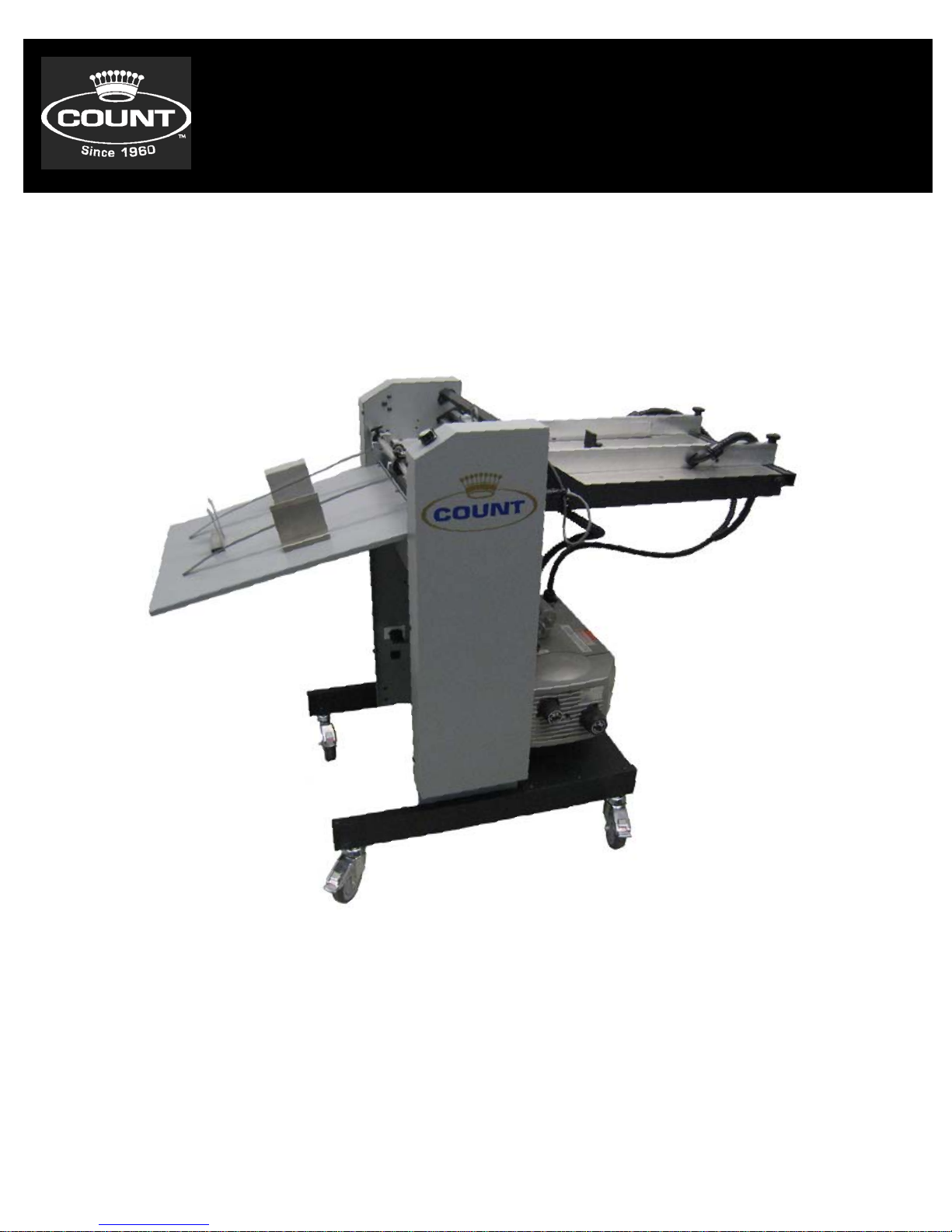
Perfmaster Air
V3
12-2015
Date ___________________________________
Page 2

TABLE OF C ONT ENTS
SPECIFICATIONS…………………………………………………………………………………………….3
SAFETY PROCEDURES/CARE & MAINTENANCE.………………………………………………….4
COMPONENT IDENTIFICATION…………………………………………………………………………5
DELIVERY TRAY ASSEMBLY…………………………………………………………………………….6
PAPER STOP ASSEMBLIES………………………………………………………………………….….7
MACHINE CONTROLS …………………………………………………………………………………...8
PUMP CONTROLS.............................................................................................9
PULSED FEED CONTROLS ………………………………………………………………………………….9
FEED TABLE ....................... .................... ..................... ............................................
Component Identification…….…………………………………………………….10
Adjusting Feed Rails………..……………………………………………….………11
Micro Skew Adjustment ………………………………………..........………….12
Setting the Automatic Feeder…………………………………………………….12
Height Adjustment Caliper…………………………………………………….....12
Loading the Feeder…………………………………………………………………..13
Feeding Notes…………………………………………………………………………13
Replacing the Vacuum Orings.……………………….…………………………..14-15
ROTARY PERF & SCORE ASSEMBLY………………………………………………………………..16
Remov
ing the Perf Shaft to Change Configurations………………………17-18
TROUBLESHOOTING……………………………………………………………………………………….19
2
Page 3

ELECTRIC AL SPECIFICATIONS
Power Requirement: 110v, 60 HZ, AC, or International 230v, 50/60HZ, AC
20 amp line required CHECK MACHINE LABEL.
Circuit Protection: Motor................…………… …………..3 AMP Circuit Breaker
NOTE: Older buildings, overloaded lines, and bad grounds can affect the
operation of your Perfmaster Air V2. A regulated ded icat e d line is
recommended.
OPERATING SPEEDS
MODE TRANSPORT SPEED 8 1/2 x 11 Sheet Pulsed Stream
(Feet per Sec.)
Perf Mode variable 23000 sph 32000 sph
SPECIFICATIONS
Net Weight: PERFMASTER AIR V2……………………………………………..350 lbs
Overall Dimensions: …………………………………………………………………..32”Lx27”Wx26”D
Boxed Dimensions: …………………………………………………………………48”Lx48”Wx52”H
Min. Sheet Size: ………………………………………………………………..3”x5-7/8”
Max. Sheet Size: …………………………………………………………………18”x20”
NOTE: The Perfmaster Air V2 is capable of handling many types of applications above
and beyond the standard specifications. It is possible to feed quite a variety of jobs,
from 30” sheets to die cut stocks. However, the performance of the Perfmaster Air V2
on these special applications is directly related to the experience of the operator.
3
Page 4

BEFORE USE:
• Read through the owner’s manual. Follow instructions CAREFULLY.
• NEVER use a wet area. Electric shock could occur.
• Use a GROUNDED outlet and a GROUNDED circuit. Do no use ungrounded
equipment on the same circuit.
• Always use a dedicated line. DO NOT use with line splitting surge protector.
DURING USE:
• Keep fingers and hands away from score blades, perf blades, and rubber
rollers.
• Keep cords clear of moving parts.
AFTER USE:
• Turn off machine at the side panel, then unplug the main power cor d. This
will prevent damage to your machine by power/voltage spikes.
• To unplug cords, always grasp the plug body, never pull on cords to
disconnect. Wire fatigue and possible shock could result from improper
disconnect procedures.
BE ALERT! BE CAREFUL!
SAFETY PROC EDURES
CARE AND MAINTENANCE
The PERFMASTER AIR V2 is a precision ma chine. It is very important to keep it free of
excessive dust, dirt and foreign matter. We recommend that you keep the machine
covered when not in use.
BEARINGS/BUSHINGS: The bearings are sealed roller bearings and are designed to
be self lubricating, however dirt and dust can get into them causing clogging and dirt
build up. It is recommended to oil them daily under heavy use or monthly under light
use. The Bushi ngs are Bronze and do require lubrication more frequently. Oil these
once a week under heavy use.
RUBBER ROLLERS: These tend to harden when ex posed, and in use, use “water t o
clean them before and after each use. This will increase the life and require less
replacement. “Do not use Blanket Wash or Ot her Cleaners.”
REMOVEABLE SCREWS: When these show signs of wear or stripping, replac e as soon
as possible. If these strip or hollow out they can be costly to remove. If you do keep
your Perfmaster Air V2 clean and in top condition, it will give you years of service.
4
Page 5
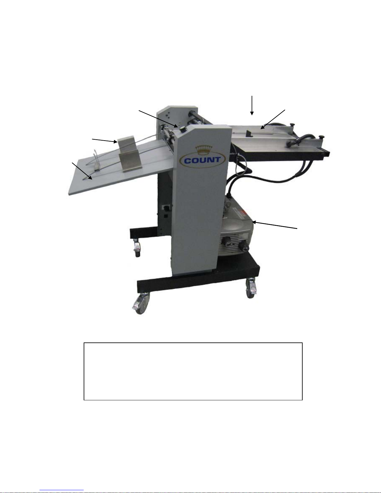
COMPONENT IDE N TIFICAT ION
Air Feed Table A ssembly
Delivery Tray
Pump with
Perf and Score Assemblies
Paper Stop
Feed Table Assembly
Feed Rail Assembly
REFERENCES
Pg. 10
Delivery Tray Pg. 6
Paper Stops Pg. 7
Pump with V acuum Valv e Pg. 9
Perf and Score Assemblies Pg. 16
Vacuum Valve
5
Page 6
PERFMASTER AIR V2
Setting up your Perfmaster Air V2
This machine is 90% ready to go when it arrives on your dock, there are only a few
items that need to be put into position before it is ready to use. Those 2 items are
below:
DELIVERY TRAY ASSEMBLY
INSTALLING THE DELIVERY TRAY
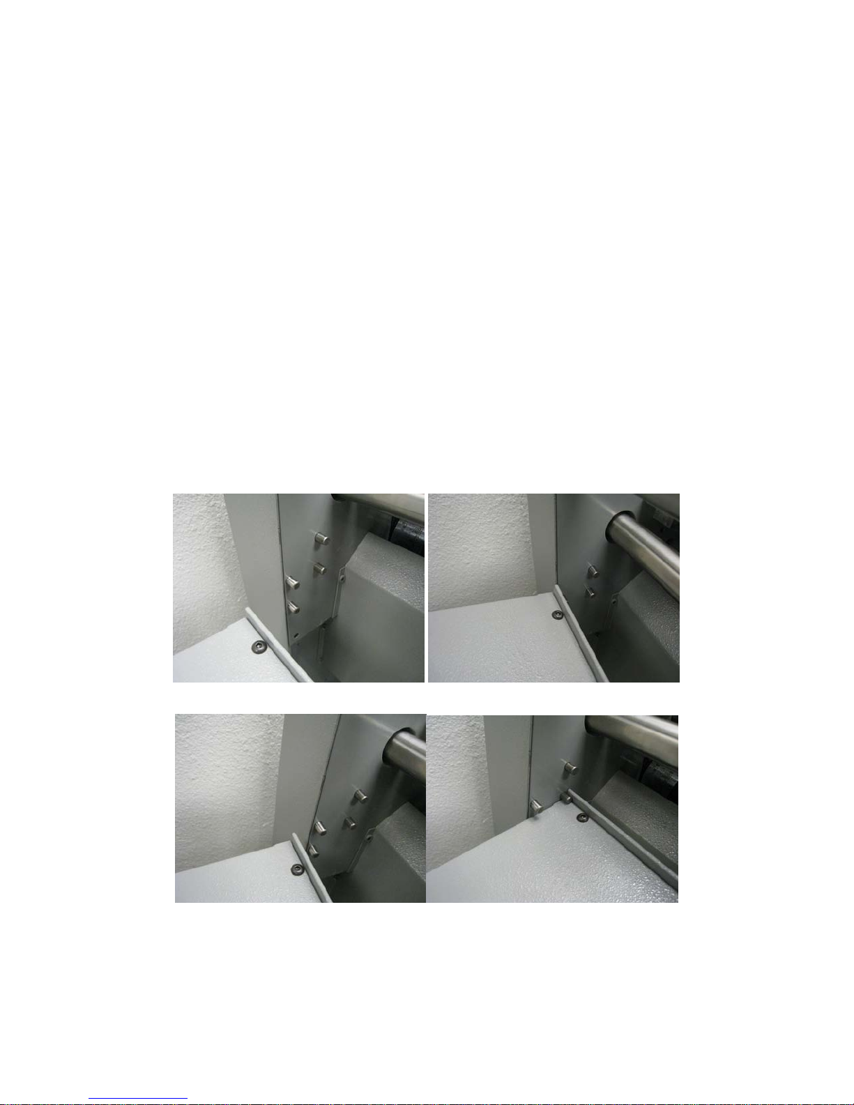
There are 2 positions for the receiving tray on the Perfmaster Air V2 the upper po sition
is for short runs where the tray will not need to be as deep. The lower is for longer runs
so the tray would need to be empty less often. Position the tray to slide it under the
dowel pins and rest it on the lower dowel pins.
Upper Position shown below
Lower Position shown be low
6
Page 7
PAPER STOP ASSEMBLIES
INSTALLING THE PAPER STOPS
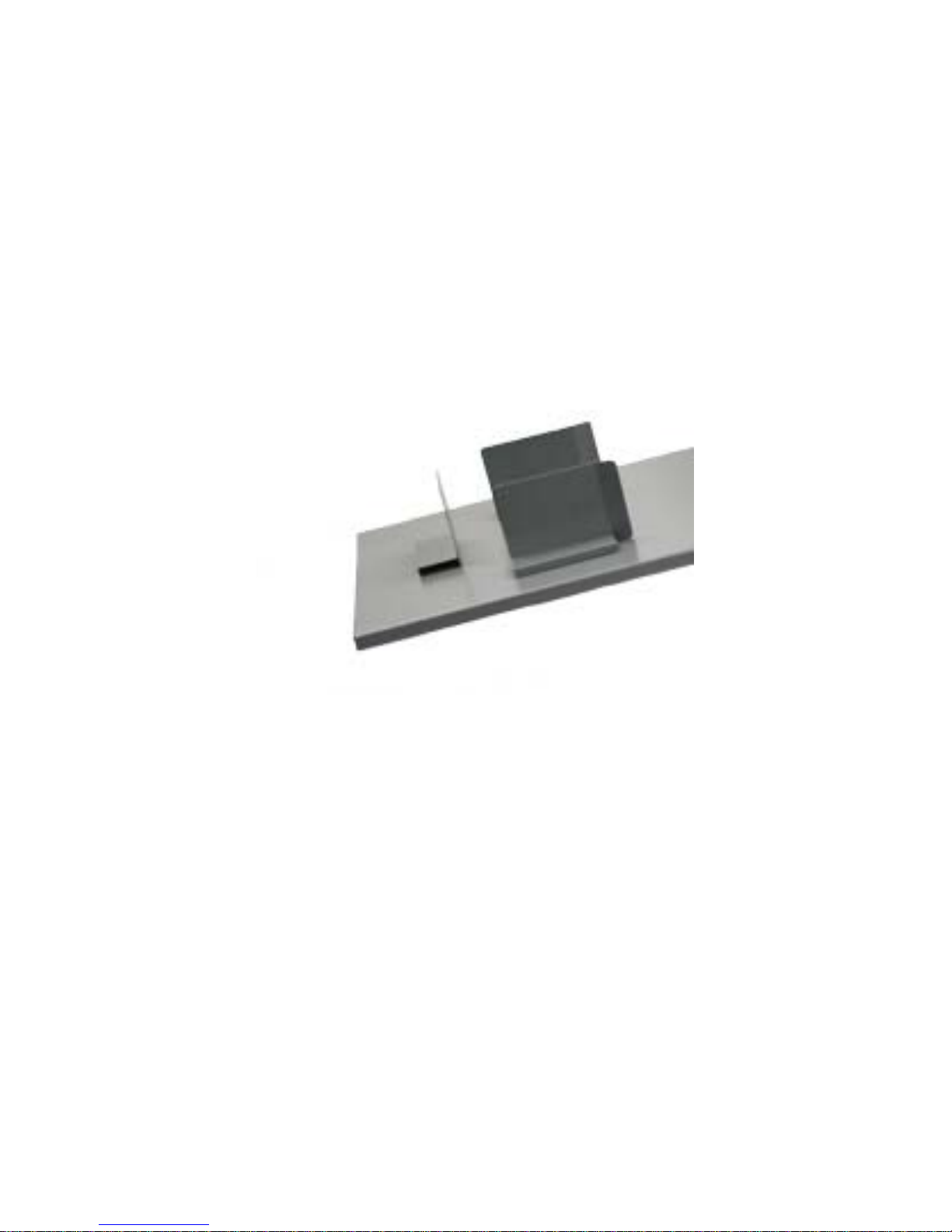
There are 3 different paper stops. 2 will have bends and 1 will be straight. the
straight paper stop is the rear or back paper stop. the other 2 are teh right and left
paper stop and should be positioned as shown below. The hold there position using a
magnet which makes it easy for adjustment. The positions for the pa per stop s will
change for each individual job. If the paper stops are set to close the paper will hit
them as it exits the machine and will cause a paper jam. If they are set too loose the
paper will stack in an unorganized manner. Getting the position correct is imperative to
smooth operation of the machine.
Now that the Machine is setup lets learn how to use the machine. Th e sections below
will guide you through the operation of the machine.
7
Page 8
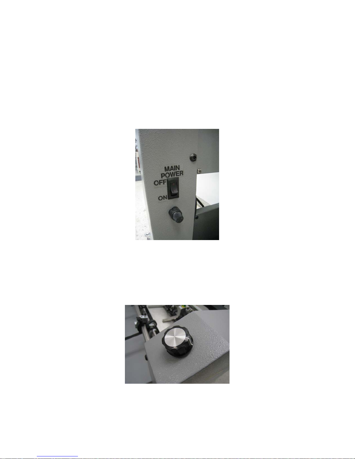
MACHINE CONTROLS
There are many switches on the Perfmaster Air V2 and it is very important that you
know and understand what each of them does.
MAIN POWER
On the Operator side cover at the bottom on the right side is the main power switch.
This is the on and o ff power for the machine. Also there is a 3A fuse.
SPEED CONTROL
Speed control is done with a knob on the top of operator side cover. This is a variab l e
speed machine. To start the motor turn the knob clockwise until you reach the desired
speed. To stop the motor on the machine turn the speed pot counter clockwise.
8
Page 9
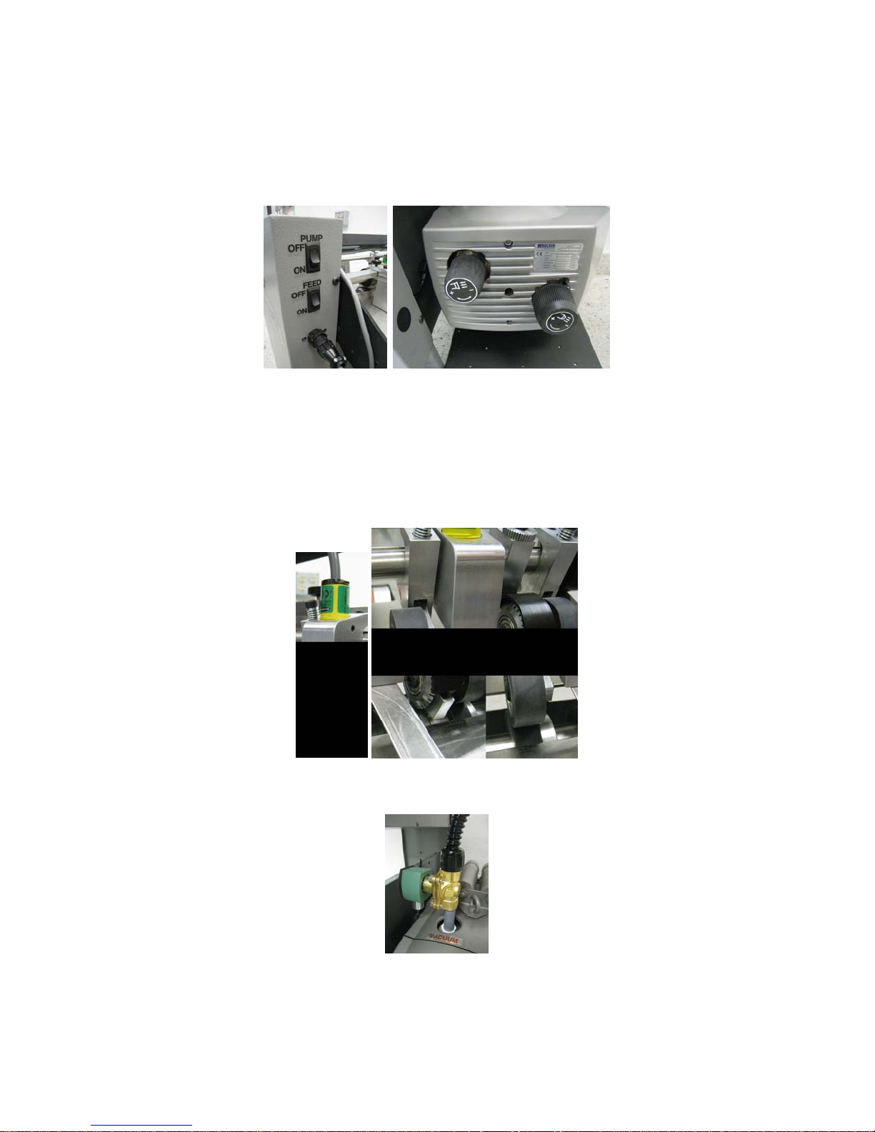
PUMP CONTROL S
On the Operator side cover at the top on the right side is the pump switch. This switch
turns the pump on and off. Use the knobs on the pump to control the output of the
pressure and vacuum.
PULSED FEED CONTROLS
The Feed Switch is the control of a pulsed suction valve that allows the machine to fully
control the feed of the paper. This mode of operations is a much more consistent way
to run the machine. While the output speed is slower the end result is much more user
friendly feed. To use the pulse suction use the FEED switch just below the pump on/off
switch. When using the pulsed feed it is very important that the proximity sensor is
adjusted correctly. See the images below to identify the pulse sensor and position it
needs to be in.
Make sure nothing is below the proximity sensor and it is positioned between the sheet
metal and perf shaft. If this posit ion is not correct the pulse feed will not work
and the suction valve will stay off.
Air Valve Assembly
9
Page 10
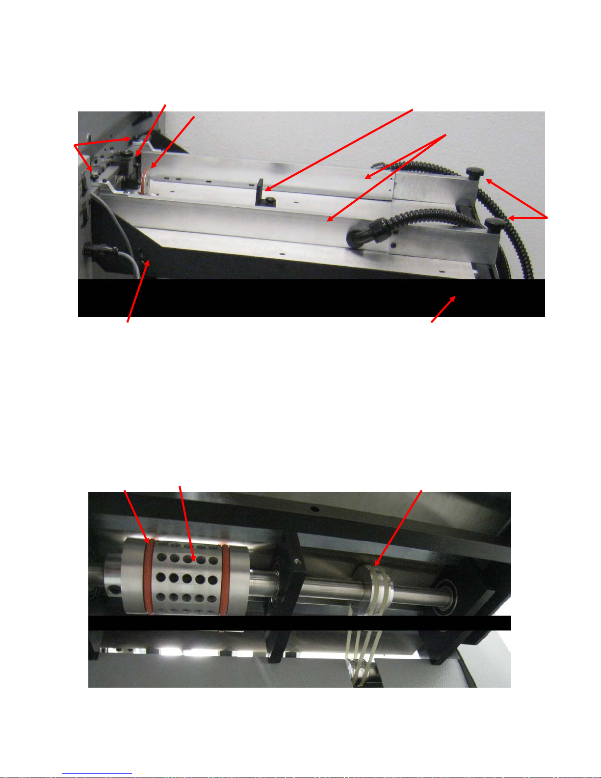
FEED TABLE COMPONENT IDENTIFICATION
2
3 4 5
8
9
10
11
1
6 7
6. Vacuum Pickup Point Adjustment Knob
1. Height Adjustment Caliper
2. Feed Rail Lock Knob Front
3. Paper Back Stop
4. Feed Rails
5. O-ring Caliper Assem bly
7. Micro Skew Adjustment Knob
8. Feed Rail Lock Knob Rear
9. Vacuum Wheel O-ring
10. Vacuum Whe el
11. Vacuum Whe el O-ring Drive Belt
10
Page 11

ADJUSTING THE FEE D R AILS
The feed rails on your PERFMASTER AIR V2 are designed to adjust easily in case of a
problem with crooked feeding. By loosening the feed rail alignment lock knobs you can
move each rail independently to square them to your stock. To maintain an accurate
perf or score, it is important to get the rails as aligned and snug to the sheet as possible
without “squeezing” the sheet, as this will create drag and cause the sheets to hang up
in the rails.
To adjust this correctly, use one rail as your reference, the left (operator side). Place
your stock squarely against it then bring your right rail in and tighten, looking down it
from the rear. Adjust the rail with the skew adjustment knob so it is squared to the
sheet. Then tig hten the lock knob, and place your PERFMASTER AIR V2 in perf mode.
Set a sheet in the feeder, and under the feed wheels, then press run.
Check perf by folding over and aligning the perfed edge.
Perf holes should line up within a blade’s width. If they do not line up, adjust rails
accordingly, moving your left rail first and then adjusting the right rail to square the
sheet. This may take a few attempts, but this adjustment is important to produce quality
perf and score jobs.
EXAMPLE:
SQUARING THE FEED RAILS
The constant fine tuning of the rails will make it necessary to bring the rails back to
true “square”. To do this, take a sheet of 8 1/2 x 11” cover stock and place it in the feed
table against the operator side guide. Pressing the sheet against the r ail, slide the rail
over so that the front edge of the stock lines up to the front edge of the feed table.
Loosen the feed rail adjustment lock knob, and use the skew adjustment knob to adjust
the rail so that the sheet is aligned with the left to right with the edge. Once this is
done, slide the opposite side guide into position and adjust it to the edge of the sheet.
Your rails should now feed the sheet perfectly aligned providing a straight perf or score.
11
Page 12
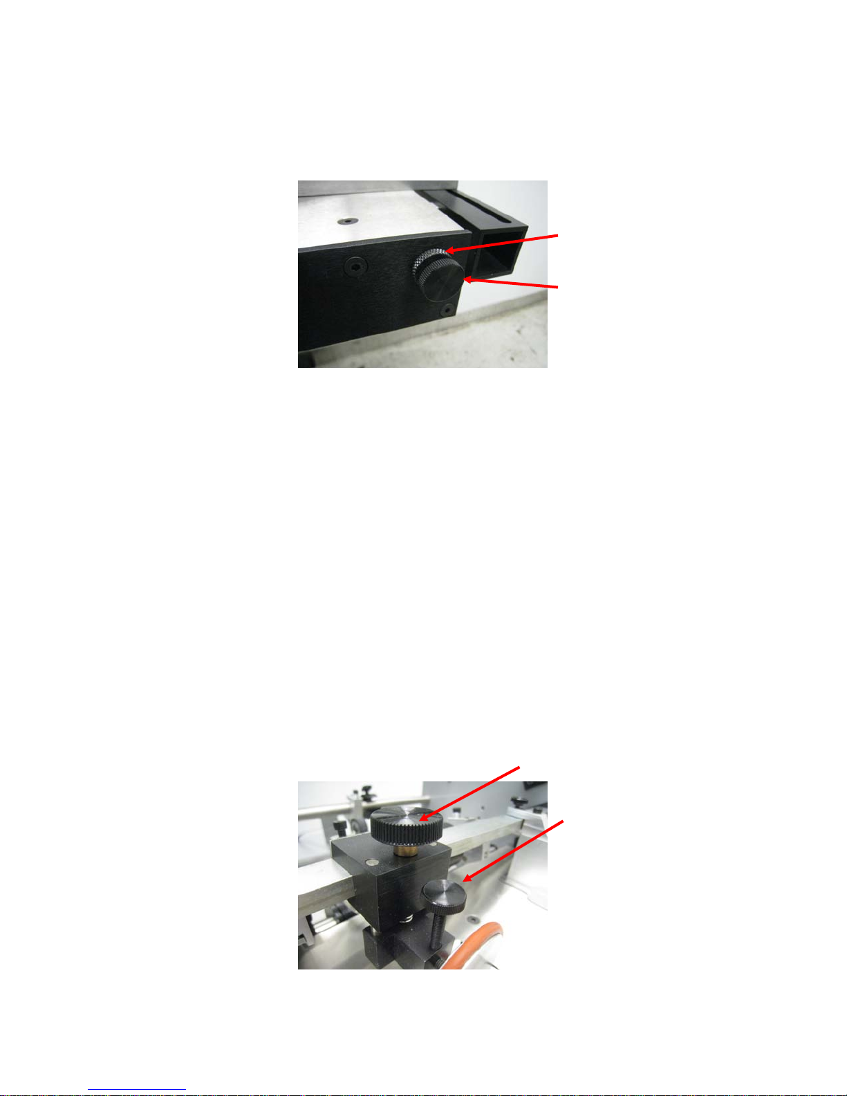
MICRO SKEW ADJUSTMENT
Lock Knob
Adjustment Knob
The micro skew adjustment will allow for the rear adjustment of the feed rails. It
adjusts both of the rear feed rails at the same time. This makes it easier to adjust for
and straighten the perf or score.
SETTING THE AUTOMATIC FEEDER
For efficient Auto-feeding, the setting of the caliper to the vacuum wheel is very
important.
Use a piece of the stock to be run as a “feeler gauge”. Place a
sheet under the feed wheels, turn the feed wheel adjustment screw
(Counterclockwise to raise, clockwise t o lower)
so that the paper can slip freely under the wheels. The feed wheels should
be barely touching the stock. If during the feeding you begin to get
doubles, lower the feed wheels just enough to stop the double sheeting.
The paper between the friction plate and the auto feed wheel must move
freely and should not be gripped.
HEIGHT ADJUSTMENT CALIPER
The caliper setting is what ensures the feeding of one sheets and prevents the feeding
of double sheets. It is very important that this caliper is set correctly. To set the caliper
take one sheet of the stock you are running and slide it between the caliper and vacuum
wheel. Take a second sheet and slide it back and forth, in and out while lowering the
height adjustment until the second sheet cannot slide under the caliper. DO NOT
OVERTIGHTEN! It is very important that the sheet is not pinched in anyway.
Height Adjustme nt Knob
Caliper Disk Lock Knob
12
Page 13
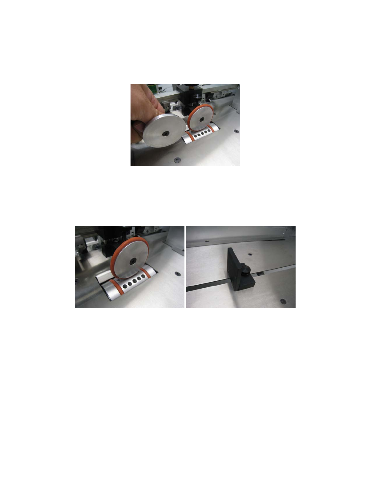
There are 2 different calipers the o-ring and the metal caliper. The metal cal iper is
designed to work better with heavy stock and the oring caliper is designed to work with
lighter stocks. Use the oring caliper when running any multipart forms.
LOADING THE FEEDER
Take the paper and load the feed tray. DO NOT OVER LOAD. The weight and size for
the stock you are running will determ ine how much can be loaded in the feed rails. The
paper should sit snug between the caliper and back stop. Do not pinch the paper as it
will affect the feeding consistency.
• When set properly, the feed is very efficient and flexible. When neglected it can
become very frustrating to run even the simplest job. The adjustments
previously discussed are very important.
• The Perfmaster Air V2 is capable of running 20lb. single sheets, 4 part forms and
100 lb cover. It is also very capable of handling gloss, coated, and even
laminated stocks. Its flexibility is directly related to the operator’s experience.
• All carbonless sets are fed into the Perfmaster Air V2 with as little air pressure as
possible. Use just enough pressure to pull a single multi par t form.
FEEDING NOTE S
13
Page 14
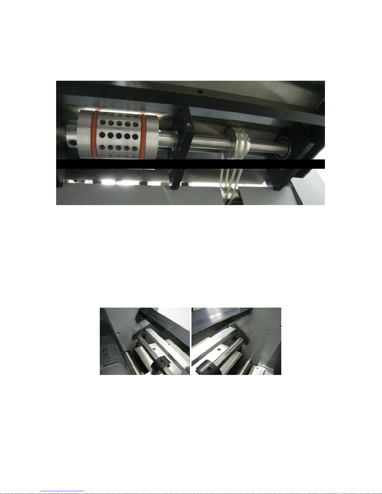
REPLACING THE VACUUM RUBBER ORINGS
There are 2 different orings on the feed table. The Drive orings and the vacuum wheel
orings. to replace the drive orings remove the 2 screws the mount the outside bearing
block from the top of the machine. then slide the bearing block off the shaft. loosen
the oring put the new oring drive pulleys on the shaft and roll them over the oring pulley
and over teh machein drive pulley.
To replace the vacuum wheel drive orings you must remove the table. To remove the
feed table you must take off all of the pressure adjustment brackets including any perf,
score assemblies, pulse sensor assemblies, and paper hold downs. Disconnect the
pumps lines from the pump. Disconnect the oring drive belts from the drive assembly of
the machine. Loosen and remove the feed table mount screws shown below.
Lift the feed table off and set it on a table. Remove the six flat head screws on the front
of the table shown below.
14
Page 15
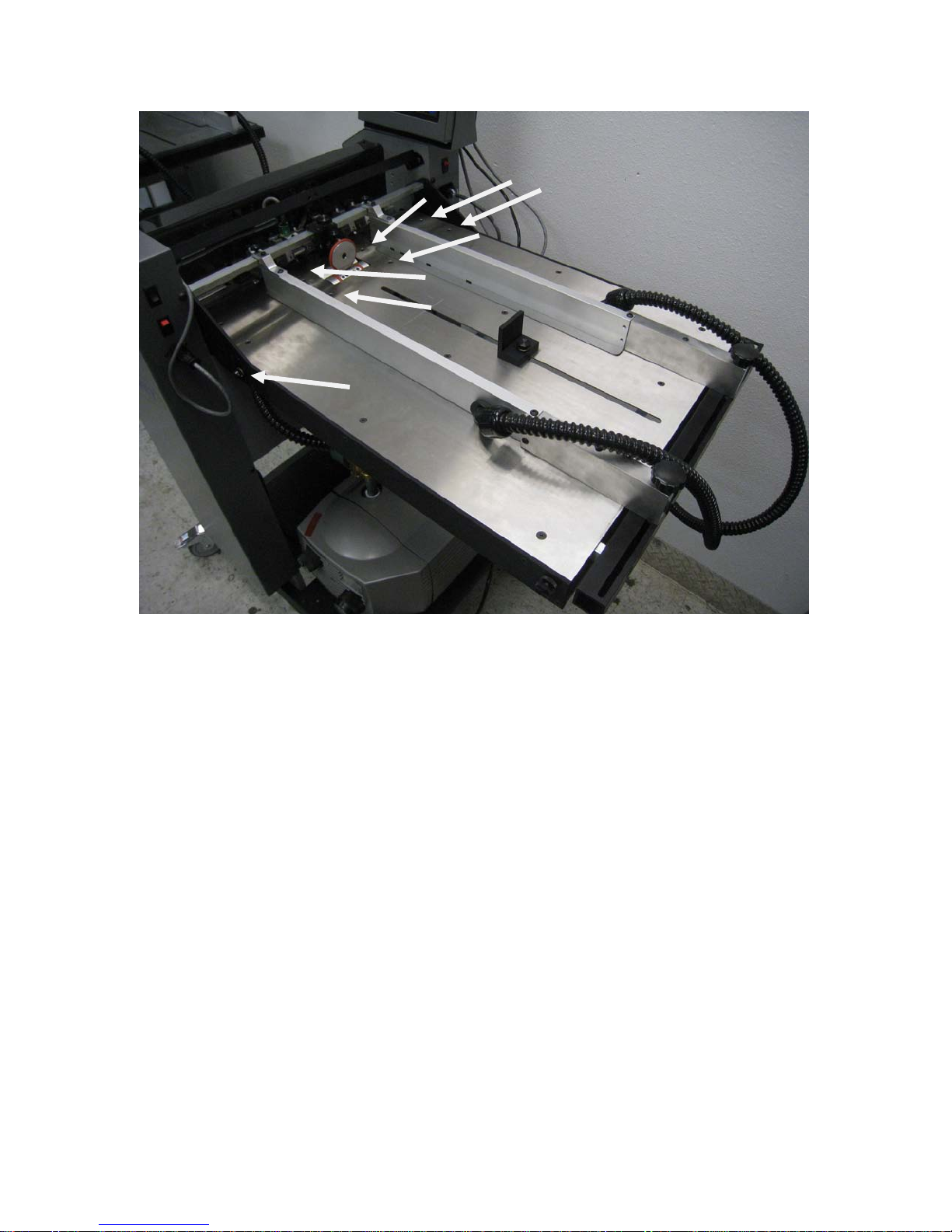
these are the bearing block screws. Also remove the vacuum pickup point adjustment
knob from the operator side of the feed table. Now all the lower assemblies will drop to
the table. Cut the old orings off the vacuum wheel roll the new orings on the vacuum
wheel and reinstall in the reverse order.
15
Page 16
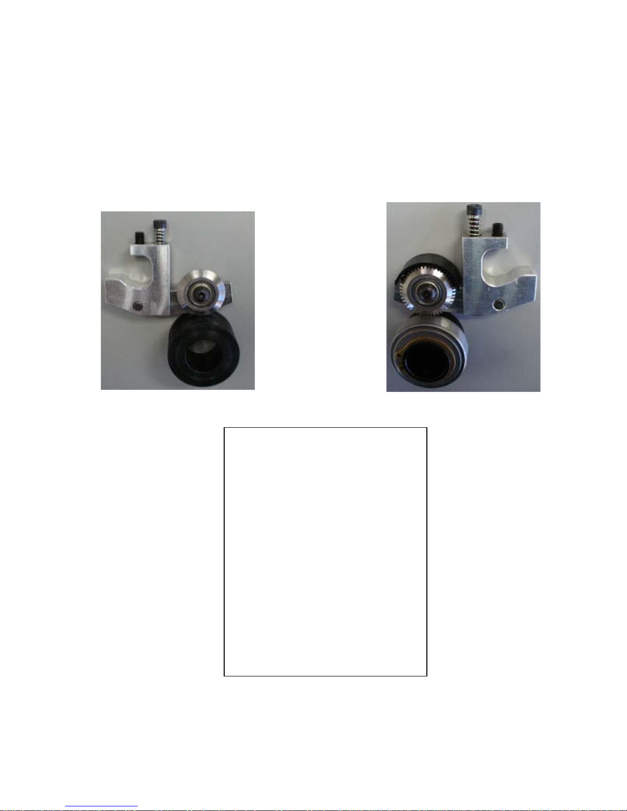
PERFORATING AND SCOR ING A SSEMBLIE S
For removing and old blade and attaching a new blade to the pressure adjust mounting
bracket, remove the (1) button head cap screw. BE SURE TO TIGHTEN THE SET
SCREW SECURELY TO THE BAR. Once you have the upper and lower perf assemblies
in place, you can tighten the half dog screw.
Complete: #S-APP-0129 Complete: #S-APP-0139
Part No. Description
H-0215 Screw-10-32x1/2” button head
H-0250 Screw-10-32x 1 1/2”socket cap
H-0270 Screw-1/4”-20x1/4” socket set
H-0275 Screw-1/4-20x1/4” socket set
H-0278 Screw-1/4-20x1/4” socket half
H-0456 Washer – flat .20
H-0580 Compression spring 1 ½”
F-0403 315-s4 0 silicone gripper wheel
F-0425 Fo rward roller mo un t ap -app
F-0430 Fo rward roller (rubber only)
S-APP-0116 Roller wheel assembly
S-APP-0131 Score blade assembly
S-APP-0141 Perf blade assembly
S-APP-0132 Lower score hub a s sy . Hub ap
S-APP-0142 Lower perf assy. Hub app
S-APP-0622 Bracket-perf/score pr es ,adj.
socket
dog
assy
16
Page 17
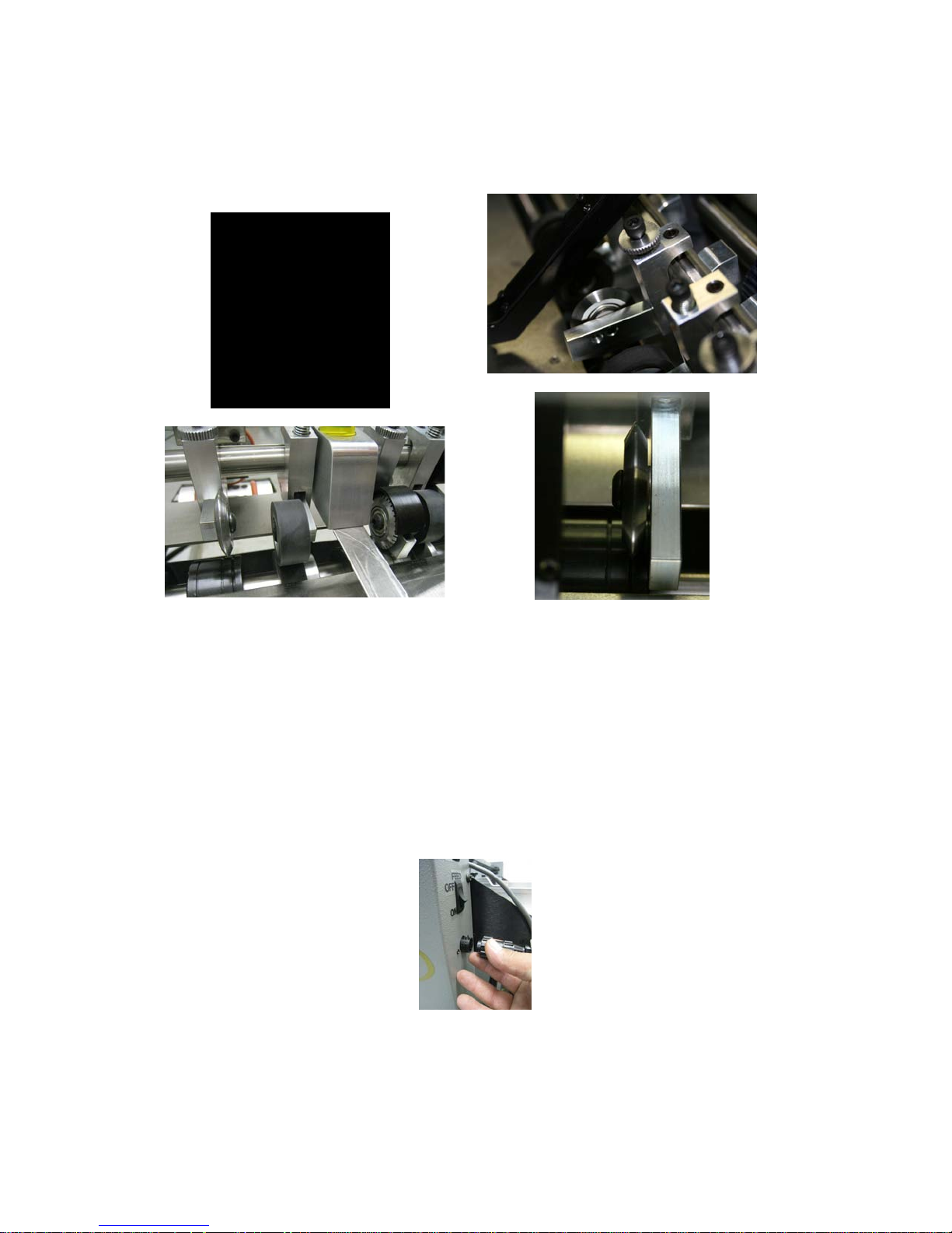
GRIPPER WHEEL PERF-SCORE MOUNTING
Rubber Grip Wheel Position
Score Wheel
Position your score blade as desired. Scores should be made so that the blade runs on
the side of the sheet that will be on the inside of the finished fold. Scores may be made
on the EZ CREASER in three differe nt ways using the different grooves on the lower
score assembly.
REMOVING TH E PERF SHAFT
Make sure a l l the upper perf, scor e, and roller assemblies are lifted. Loosen the brass
tip set screws on the lower assemblies. Loosen the operator side cover. Disconnect the
pulse feed sensor.
Remove the cover and rest it on the ground. Locate and remove the perf shaft lock
collar.
17
Page 18
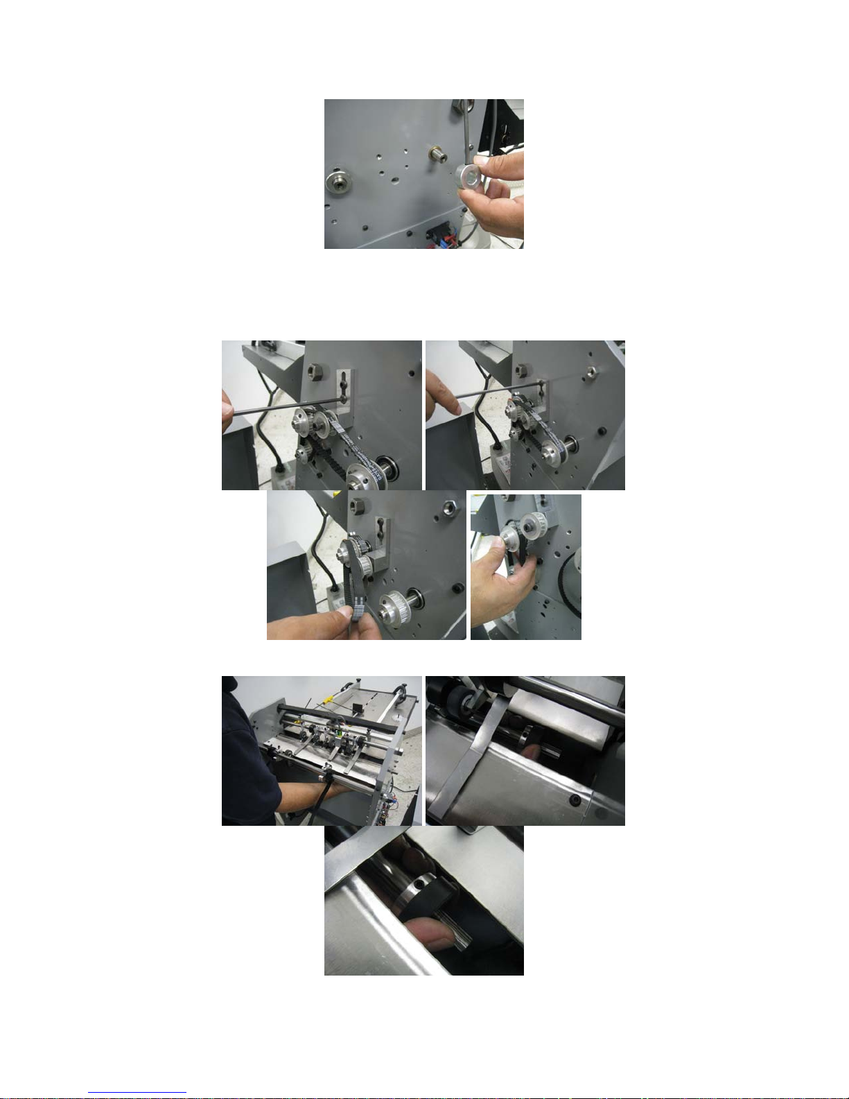
Next, remove the non-operator side cover. Loosen the belt tensioner idler pulley
bracket. You do not need to remove these as loosening them will allow en o ugh
movement to free the belt. Remove the belt. Walk the motor belt off the inner pulley. If
it is too difficult to walk off you could loosen the motor and pull it up as it is mounted in
slots.
Reach in under the exit side of the machine with your right hand and slide the shaft out
of the left side enough to slide the assemblies on and off the shaft.
reverse procedure to install components back on.
18
Page 19

TROUBLE SHOOT ING
• POWER DOES NOT TURN ON
1. Check fuse on side cover.
2. Check outlet for power.
• FEED TABLE NOT FEEDING CORRECTLY
1. Check Caliper Adjustment .
2. Feed wheels do not have equal p r essu r e on t h em , c h eck adjustment.
3. Check pulse sensor alignmen t.
• SHEETS NOT FEEDING STRAIGHT
1. Unequal feed wheel pressure.
2. Align feed rails “check for squ ar en ess”. This can be ch ec k ed by the lead edge
of the paper feeding into the machine should line up with the front edge of the
feed plate.
3. Not enough pressure on fo rw ar d in g rollers.
4. Clean ALL rubber rollers.
• PERF IS NOT S TRAIGHT
1. Check for equal pressure on all grip wheels and that none are hanging up.
2. Recheck all steps under (SHEET NOT FEEDING STRAIGHT)
• PERFORATION IS NOT CLEAN OR CUTS SHEETS
1. Not enough pressure on p er f wh eel.
2. Perf blade is worn.
19
Page 20

251 Wedcor Avenue, Wabash, Indiana 46992
Website: www.countmachinery.com Email: Info@martinyale.com
Fax: (260) 563-4575
M-S027959
Rev. 1 1/31/2017
 Loading...