

Page 1
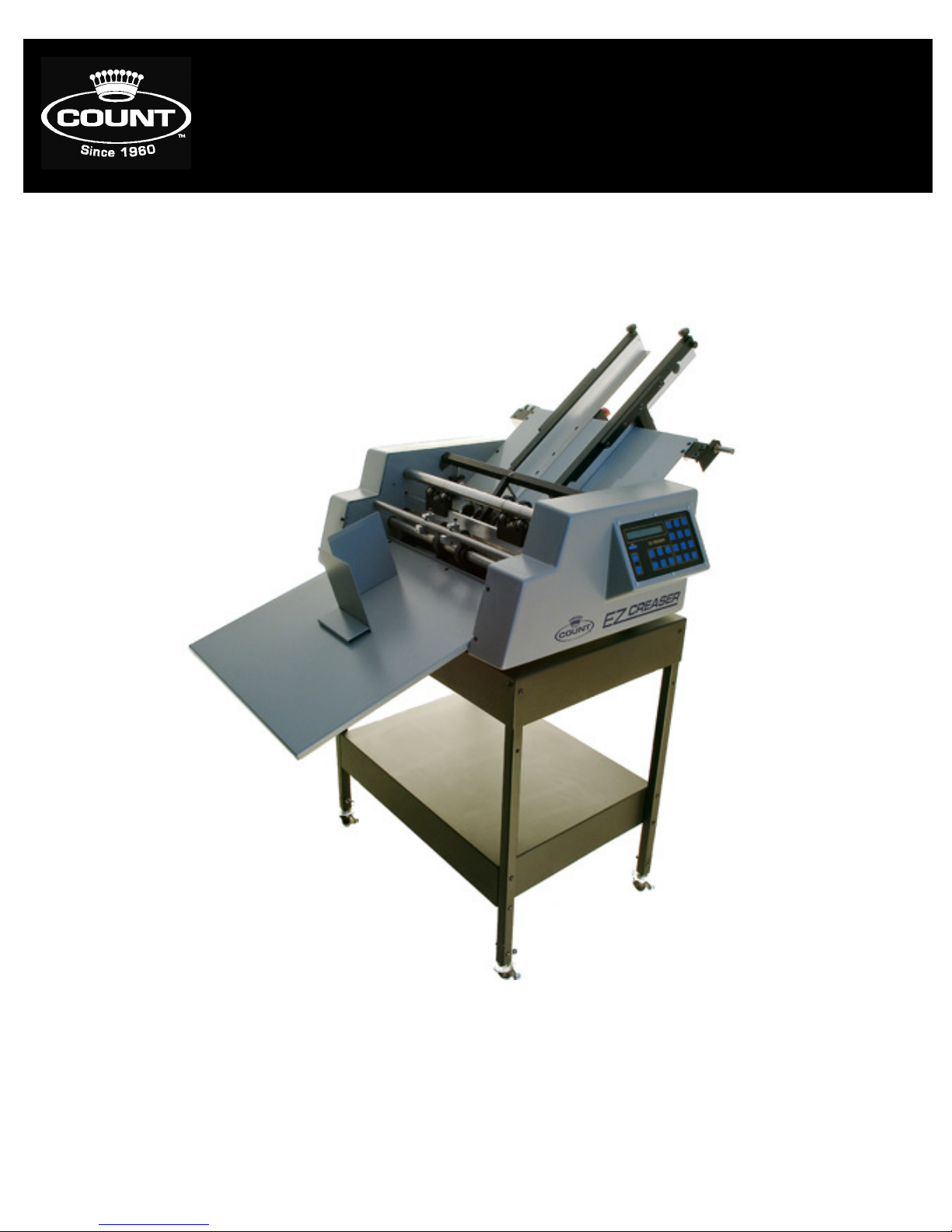
EZCREASER
4-2009
Version 1.6
Serial Number ___________________________
Date ___________________________________
Page 2

INTRO LETTER
Congratulations,
You have purchased the most versatile automatic creasing machine on the market today. Designed to
accommodate the demands of finishing digitally produced media, the EZ Creaser efficiently applies a
rotary actuated compression crease, leaving a crisp, sharp score with no cracking of the image after
the fold, on both the outside and inside creased edge.
Counts trademarked RAC System assures a consistent, controlled compression that is easily adjustable
to the demands of any sensitive media.
The EZ Creaser with it’s microprocessor driven transport promises many years of profitable operation.
Your EZ Creaser was manufactured at Count’s headquarters in Escondido, California. We are proud to
build quality equipment and stand behind our machines knowing that the quality of our product is
exceeded only by the staff which supports it.
Thank you for choosing Count.
Sincerely,
David M. Gilbert
Page 3

TABLE OF CONTENTS
(JANUARY 2007)
SPECIFICATIONS…………………………………………………………………………………………….1a
SAFETY PROCEDURES/CARE & MAINTENANCE.………………………………………………….1b
COMPONENT IDENTIFICATION…………………………………………………………………………2
SETTING UP YOUR EZ CREASER……………………………………………………………………….3
W/ Optional Stand………………………………………………………………………3
MICROPROCESSOR CONTROLLER EZ CREASER………………………………………………….4
Transport Operation Controls……………………………………………….………5
Programming Controls (mode Selection)…………………………….……..…5
Programming for Creasing………………………………………….…….…………6
Setting up Creasing…………………………….……………………….……….……6
Batch Counter………………………………………………………………….……….7
Total Counter……………………………………………………………………………8
Double Sheet Detector………………………………………………………………8
Programming Notes…………………………………………………………………..8
DELIVERY TRAY ASSEMBLY…………………………………………………………………………….9
FEED TABLE ASSEMBLY………………………………………………………………………………….9
Component Identification…….…………………………………………………….9
Adjusting Feed Rails………..……………………………………………….………10
Setting the Automatic Feeder…………………………………………………….11
Fanning the Paper…………………………………………………………………….11
Loading the Feeder…………………………………………………………………..12
Replacing the Feed Wheels………………………………………………….……12
Feeding Notes…………………………………………………………………………12
Replacing the Friction Plate………………………………………………..……..13
Checking the Sensor…………………………………….…………………………..13
Perf Shaft & Strike Plate……………………………………………………………14
Removing the Perf Shaft to Change Configurations………………………14
ROTARY PERF & SCORE ASSEMBLY………………………………………………………………..15
Component Identification………………………………………………………….15
Perforation & Scoring Assemblies……………………………………………….15
Gripper Wheel Perf Score Mounting……………………………………………16
Folding Direction of Paper…………………………………………………………16
RAC
System
Component Identification……………………………………………….………..17
TROUBLESHOOTING………………………………………………………………………………………..…20
SERVICE DIAGRAMS……………………………………………………………………………………….21-24
(Rotary Actuated Creasing) Assembly……………………………………….17
Adjusting RAC rollers (depth of crease)……………………………………..18
Changing Lower Crease Die……………………………………………………...19
Page 4

ELECTRICAL SPECIFICATIONS
Power Requirement: 110v, 60 HZ, AC, or International 230v, 50/60HZ, AC
Circuit Protection: Motor/Transformer………………………..3 AMP Circuit Breaker
Microprocessor……………………………..1/4 AMP Slo-Blow
Pulse Board………………………………….3 AMP Slo-Blow
NOTE: Older buildings, overloaded lines, and bad grounds can affect the operation of
your EZ Creaser. A dedicated line is best.
OPERATING SPEEDS
MODE TRANSPORT SPEED 11X17 Sheet(est) 5 ½” Sheet(est)
(Feet per Sec.)
Perf Mode 2.5 8500 12500
Crease Mode 2.0 2500 4400
SPECIFICATIONS
Net Weight: EZ CREASER……………………………………………..250 lbs
Overall Dimensions: …………………………………………………………………32”Lx27”Wx26”D
Boxed Dimensions: …………………………………………………………………36”Lx36”Wx30”D
Min. Sheet Size: ………………………………………………………………..3”x5”
Max. Sheet Size: …………………………………………………………………18”x20”
NOTE: The EZ CREASER is capable of handling many types of applications above and
beyond the standard specifications. It is possible to feed quite a variety of jobs, from
30” sheets to die cut stocks. However, the performance of the EZ CREASER on these
special applications is directly related to the experience of the operator.
1a
Page 5

BEFORE USE:
• Read through the owner’s manual. Follow instructions CAREFULLY.
• NEVER use a wet area. Electric shock could occur.
• Use a GROUNDED outlet and a GROUNDED circuit. Do no use ungrounded
equipment on the same circuit.
• Always use a dedicated line. DO NOT use with line splitting surge protector.
DURING USE:
• Keep fingers and hands away from creasing bar, perf blades, and rubber
rollers.
• Keep cords clear of moving parts.
AFTER USE:
• Turn off machine at the rear panel, then unplug the main power cord. This
will prevent damage to your machine by power/voltage spikes.
• To unplug cords, always grasp the plug body, never pull on cords to
disconnect. Wire fatigue and possible shock could result from improper
disconnect procedures.
BE ALERT! BE CAREFUL!
SAFETY PROCEDURES
CARE AND MAINTENANCE
The EZ CREASER is a precision machine. It is very important to keep it free of excessive
dust, dirt and foreign matter. We recommend that you keep the machine
when not in use.
BEARINGS: The bearings are sealed roller bearings and are designed to be self
lubricating, however dirt and dust can get into them causing clogging and dirt build up.
It is recommended to occasionally oil them under heavy use.
STRIKE DIE: The groove in the lower die should be cleaned periodically using a
toothbrush to remove any dirt or build up.
SENSOR EYE: Clean the upper and lower sensor with a Q-tip (avoid moving the sensor
to clean). Clean when necessary.
REMOVEABLE SCREWS: When these show signs of wear or stripping, replace as soon
as possible. If these strip or hollow out they can be costly to remove. If you do keep
your EZ CREASER clean and in top condition, it will give you years of service.
1b
covered
Page 6
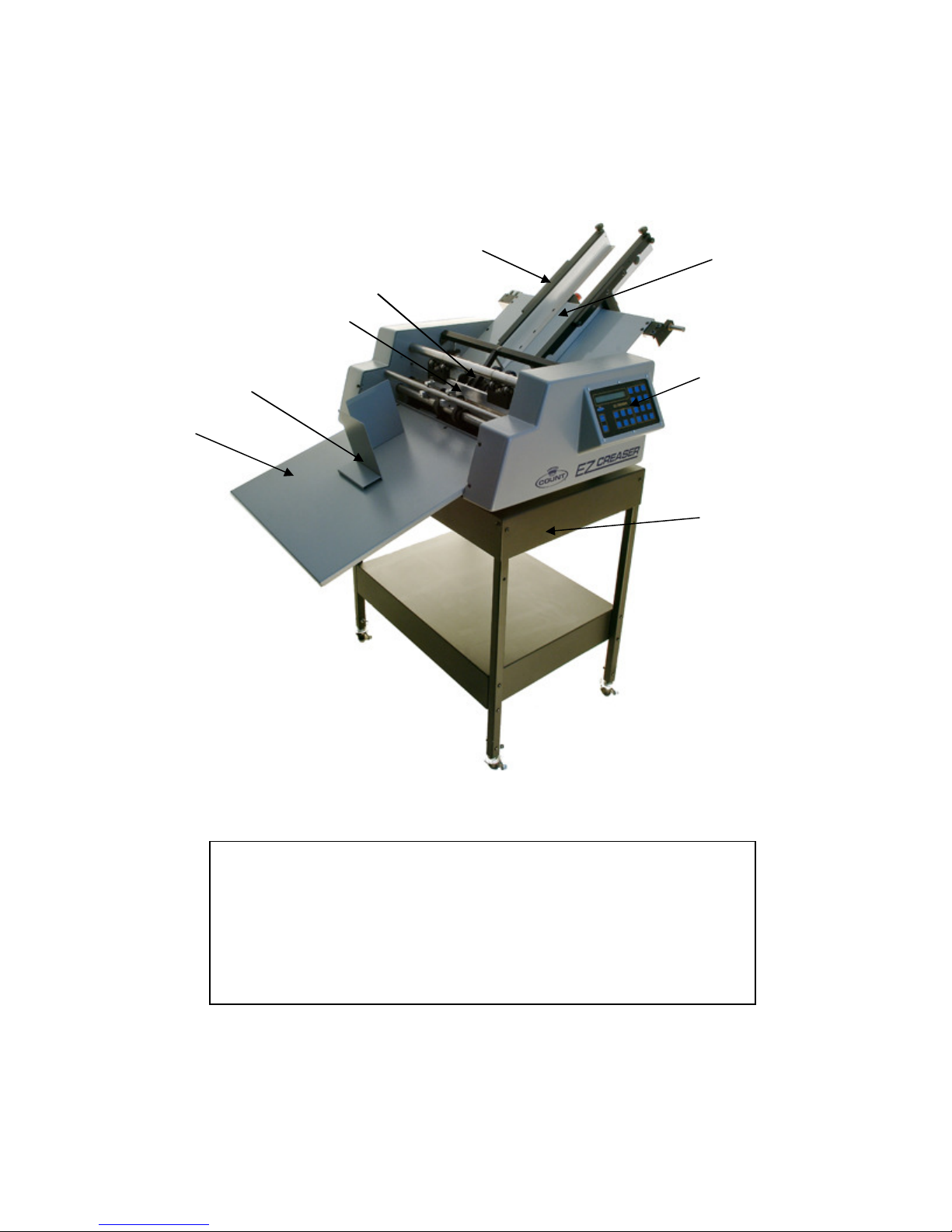
Machine Stand
Pg. 3
COMPONENT IDENTIFICATION
Feed Rail Assembly
Perf and Score Assemblies
Crease Bar
Feed Table Assembly
Paper Stop
Delivery Tray
Microprocessor Pg. 4
Feed Table Assembly Pg. 9
Delivery Tray Pg. 9
Perf and Score Assemblies Pg. 15
Crease Bar Pg. 17
REFERENCES
2
Microprocessor
Machine Stand
Page 7
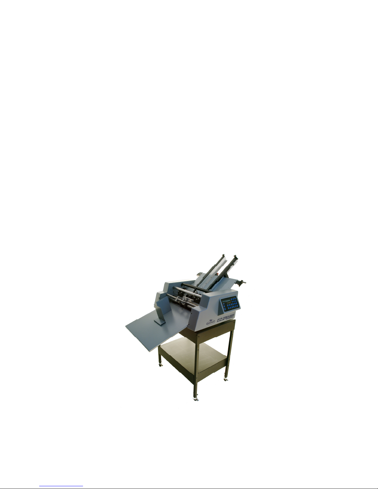
SETTING UP YOUR EZ CREASER
STAND (
1. Open top half of box and remove components.
2. Assemble stand.
3. Place machine on stand as shown below.
4. Unscrew feed rail guide shaft, slide shaft out.
Place feed rails on feed table and slide shaft
back in going through feed rail guide brackets.
5. Place delivery tray in front so tray hooks under steel dowels directly below the exit
shaft shaft. Locate the magnetic paper stops and position them on the tray.
6. Inspect the remaining parts and place them near the machine where they are easily
accessible.
7. Plug in your machine. NOTE: the EZ CREASER required only 115v so any standard
outlet will accommodate it. However, it is important that the line has a good ground.
Also make sure the circuit is not overloaded with other equipment.
(NOTE: 230v will be used for European models)
optional
)
3
Page 8

EZ CREASER
MICROPROCESSOR CONTROLLER
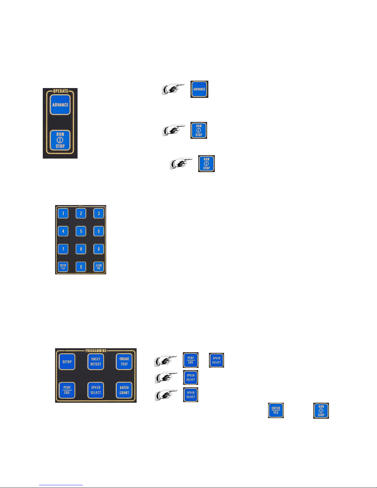
THE MICRO-CONTROLLER CONSISTS OF FOUR SECTIONS:
2. Operate Controls
3. Programming Controls
4. Data Pad
Controller Display
The LCD displays programming information, prompts response, and verifies entered
data or commands. The LCD also conducts a self-diagnosis test whenever power is
turned on. A countdown sequence from 9 to 0 will appear. If a number is missing from
the sequence this indicates a failure in a component. If this occurs, contact the Count
service department for further details. At the display of “EZ Creaser” the microprocessor
is clear and ready to accept the entries. The micro-controller is also equipped with
volatile memory so when power is turned off the EZ Creaser will retain the last
programmed entry.
1. Controller Display
4
Page 9
TRANSPORT OPERATION
• A document may be slowly advanced through the transport by
pushing and holding this button.
EXAMPLE:
The motor should advance transport at slow speed and stop
whenever finger is lifted.
• Controls on-off function of motor.
EXAMPLE:
Machine will run at mode and speed previously selected. If no
mode has been selected, it will automatically run in perf mode
at low speed.
• Machine will stop.
NOTE: If the EZ CREASER is stopped while a sheet is under the sensor,
the display will flash “sensor blocked”
••••Data Keys 0-9:
required for distances and crease designation.
••••Enter/Yes:
keys and answers display prompted questions.
••••Clear/No:
for clearing total count. Answers “no” to display
prompted questions.
PROGRAMMING CONTROLS
Speed Select:
the speed selected on the display.
Mode Select: PERF/CRS
runs in. By Default and every time your machine is powered off the machine will
start in PERF mode. Press the PERF/CRS mode button twice to enter into Crease
Mode.
EXAMPLE: DISPLAY READS:
These may be pressed until the desired mode is selected, then: Pressing
will now run transport at selected mode.
Pushing this will select speed, low, medium or high and show
Pushing this will Change the mode your machine
5
DATA PAD
Allows entry of numeric data
Stores input information from data
Erases errors entered and prompts
(Mode Selection)
CRS Mode Low Speed
CRS Mode Med Speed
CRS Mode High Speed
Page 10
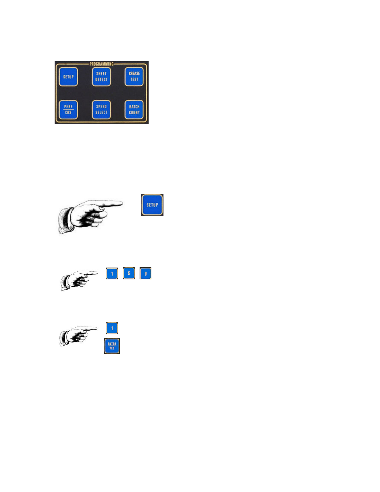
PROGRAMMING FOR CREASING
••••Set-Up: Pressing this will present a request for
the selection of a distance where the location of
the number is requested in hundredths of an inch
from the lead edge of the sheet.
••••Crease Test: Pressing this button will fire the
crease bar one time.
SETTING UP CREASING
Crease Mode: Press the PERF/CRS button twice this will put the machine in crease
mode then hit enter and follow the steps below.
EXAMPLE: DISPLAY READS:
Dist 1 = 0.00
You can now enter the desired location for your crease, from .1 to 20 inches.
Dist 1 = 1.50
Sel Crease Bar = 0
You can now select the crease bar you have selected for the job.
Sel Crease Bar = 1
End Program? Y/N
Answering yes will complete the programming sequence. Answering no will prompt the
next location for a crease (see next page) the EZ CREASER will accept up to 10 locations
to crease.
6
Page 11
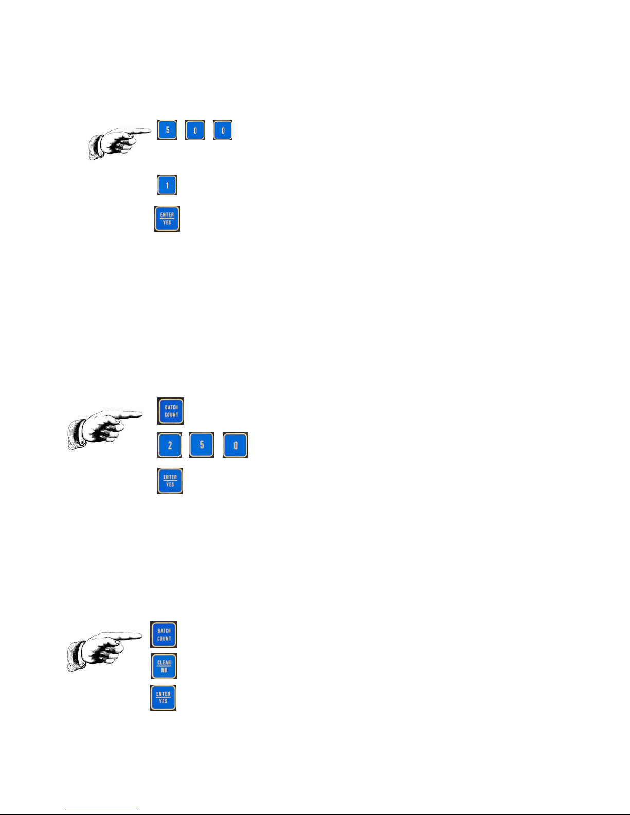
EXAMPLE: DISPLAY READS:
Dist 2 = 0.00
Dist 2 = 5.00
Sel Crease Bar = 0
Sel Crease Bar = 1
End Program Y/N Program Complete
You have now programmed your EZ CREASER to crease in two locations. Press run and
place 1 sheet on the feed table. The sheet should feed through stopping twice to crease.
If this does not occur, check your mode and make sure your selections have been
accepted. Remember, the speed and mode can be changed at any time, and will not
affect the program.
BATCH COUNTER
EXAMPLE: DISPLAY READS:
This will allow 250 sheets to pass the sensor then stop transport automatically. Pressing
run will batch another group of 250 sheets. You can set the batch counter up to 9999.0
the feature is convenient for chip boarding small groups to be padded, or wrapping
larger jobs in predetermined packages.
CLEAR BATCH COUNT: DISPLAY READS:
Batch Count = 0
Batch Count = 250
EZ Creaser
Batch Count = 250
Batch Count - 0
EZ Creaser
7
Page 12
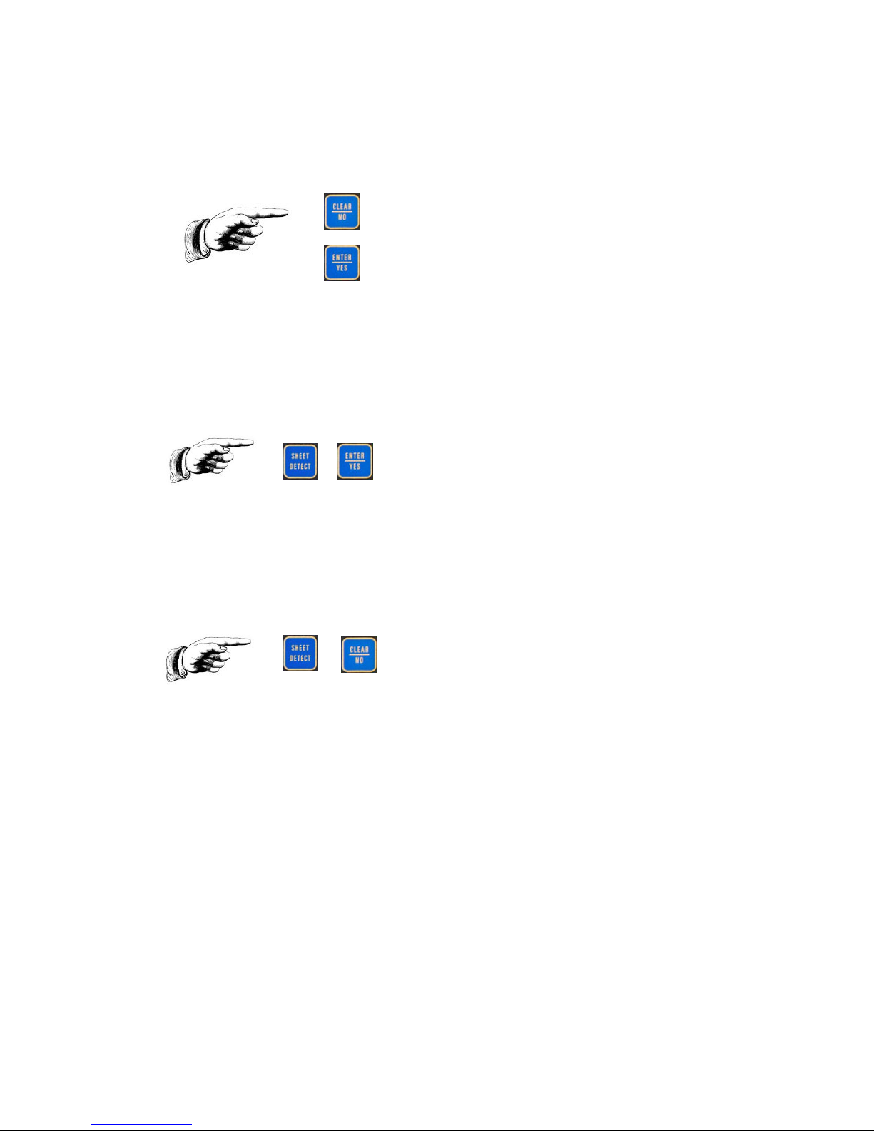
TOTAL COUNTER
The micro-controller automatically counts any paper being run through the transport.
This count is displayed as the EZ CREASER is operating and when it is stopped. To clear
the counter: DISPLAY READS
Clr Tot Cnt = Y/N
Total Count = 0
SETTING THE DOUBLE SHEET DETECTOR
Note: Sheet detector works on the basis of measurement comparison using the length
of the sheet to verify more than one sheet.
To turn on:
1. =Display will read (measuring length)
Machine will automatically start to advance
2. Place sheet of job to be run in machine
3. After paper runs through the machine will stop and a dashed line will appear in the
bottom of left corner of display, thus indicating that the sheet detector is activated.
To turn off:
1. =Dashed line on display will vanish from
display, thus indicating that the sheet
detector is off.
PROGRAMMING NOTES
• The micro controller is capable of positioning creases from 1/2 of an inch from
the lead edge to ½ inch from the tail edge and up to 26 inches from the lead
edge.
• The crease bar can be programmed to strike single or multiple locations with a
capacity of 10 locations.
• When programming multiple locations to crease, the distances must be entered
in an ascending order. For example, if 1.5 is the first location, the controller will
not accept an entry of 1.2 after this. If this is attempted, the display will read
“crease out of range”
• If the incorrect key is pushed while programming, a beep will occur and the
display will flash “keyboard sequence error”. Wait 3 seconds then respond as
prompted.
8
Page 13
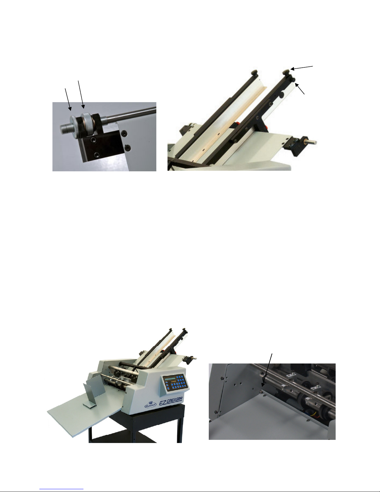
FEED TABLE ASSEMBLY
F-0640
F-0645
H-0825
S-APP
-
0005
Dowel Pins Used to
Nut –Adjustment Feed – F-0640
Micro-Lateral Adjustment Lock – F-0645 When positioning is correct, this will lock
the adj. knob in position
Micro Skew Adj Knob – S-APP-0005 Releases and tightens feed rails to
( knob T w/ ¼’-20 thread)
Feed Rail Lock Down – H-0825 Releases and tightens feed rails to
( knob assembly)
adjust for alignment
adjust for different size jobs.
DELIVERY TRAY ASSEMBLY
INSTALLING THE DELIVERY TRAY
The delivery tray is made to fit 2 different configurations depending on if the machine is
on a dedicated stand or if the machine is on a table. Position the tray to slide it under
the 2 dowel pins and rest the angle stop up.
Hold Delivery Tray
9
Page 14
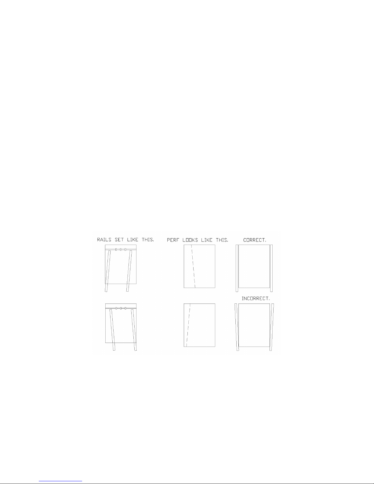
ADJUSTING THE FEED RAILS
The feed rails on your EZ CREASER are designed to adjust easily in case of a problem
with crooked feeding. By loosening the feed rail alignment lock knobs you can move
each rail independently to square them to your stock. To maintain an accurate perf or
score, it is important to get the rails as aligned and snug to the sheet as possible
without “squeezing” the sheet, as this will create drag and cause the sheets to hang up
in the rails.
To adjust this correctly, use one rail as your reference, the left (operator side). Place
your stock squarely against it then bring your right rail in and tighten, looking down it
from the rear. Adjust the rail with the skew adjustment knob so it is squared to the
sheet. Then tighten the lock knob, and place your EZ CREASER in perf mode. Set a
sheet in the feeder, and under the feed wheels, then press run.
Check perf by folding over and aligning the perfed edge.
Perf holes should line up within a blade’s width. If they do not line up, adjust rails
accordingly, moving your left rail first and then adjusting the right rail to square the
sheet. This may take a few attempts, but this adjustment is important to produce quality
perf and score jobs.
EXAMPLE:
SQUARING THE FEED RAILS
The constant fine tuning of the rails will make it necessary to bring the rails back to
true “square”. To do this, take a sheet of 8 1/2 x 11” cover stock and place it in the feed
table against the operator side guide. Pressing the sheet against the rail, slide the rail
over so that the front edge of the stock lines up to the front edge of the feed table.
Loosen the feed rail adjustment lock knob, and use the skew adjustment knob to adjust
the rail so that the sheet is aligned with the left to right with the edge. Once this is
done, slide the opposite side guide into position and adjust it to the edge of the sheet.
Your rails should now feed the sheet perfectly aligned providing a straight perf or score.
10
Page 15
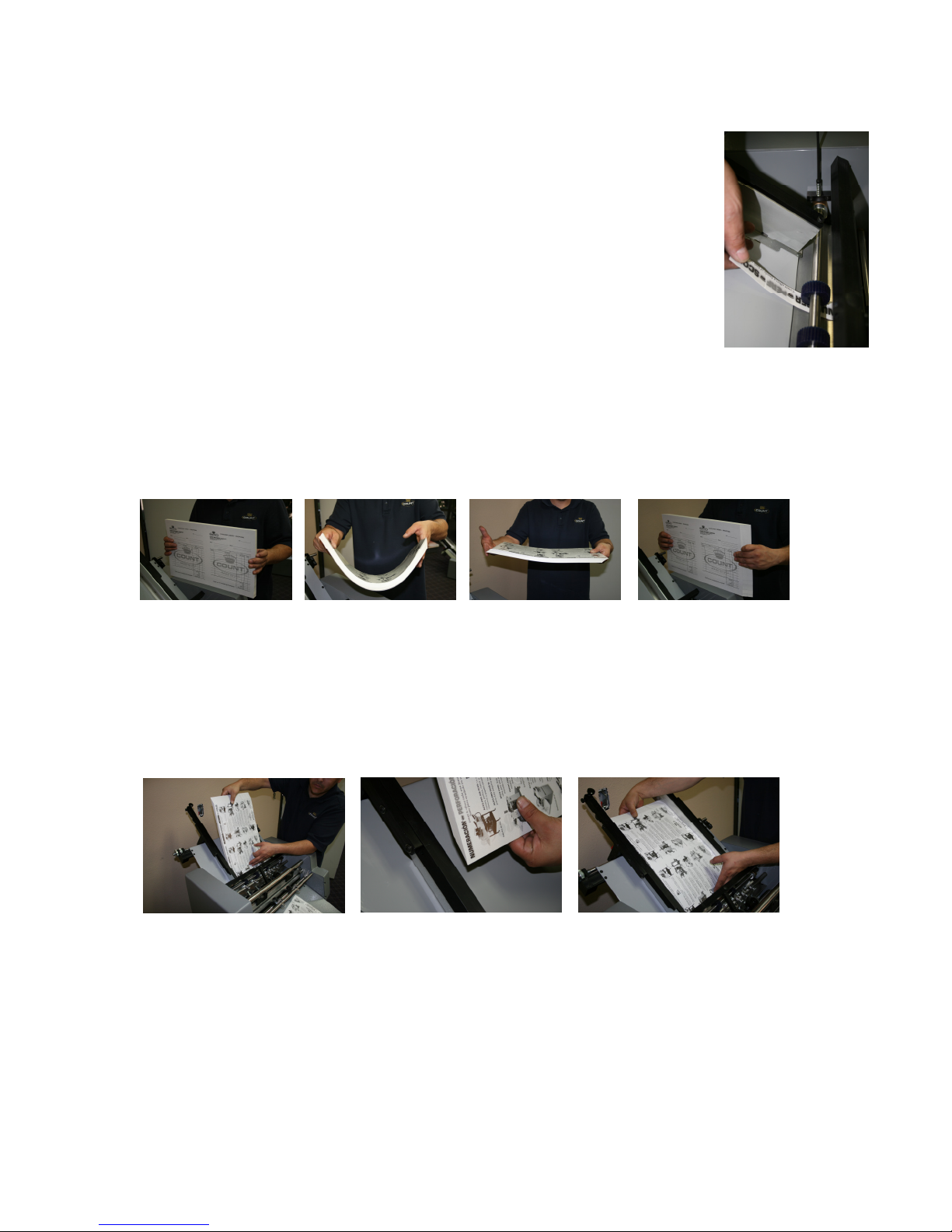
SETTING THE AUTOMATIC FEEDER
For efficient Auto-feeding, the setting of the feed wheels is very important.
Use a piece of the stock to be run as a “feeler gauge”. Place a
sheet under the feed wheels, turn the feed wheel adjustment screw
(counterclockwise to raise, clockwise to lower)
so that the paper can slip freely under the wheels. The feed wheels should
be barely touching the stock. If during the feeding you begin to get
doubles, lower the feed wheels just enough to stop the double sheeting.
The paper between the friction plate and the auto feed wheel must move (fig.?)
freely and should not be gripped.
FANNING THE PAPER
To prepare a stack of paper or sets for feeding, it must be “fanned”. This will loosen the
stack as well as form a wedge for automatic feeding.
Hold stack as pictured below
As seen above take a stack in-between 1-3 inches and hold it straight. Next fold the
stack inward, hold tight on your right hand and loose on your left then hold tight on
your right hand and loose on your left and straighten the stack back out. Gently tap the
stack on the side cover to ensure alignment and load the stack in the feeder as seen
below.
The better the spacing between the sheets and cleaner the fanning of the stack, the
more efficient the feeder will perform.
11
Page 16

LOADING THE FEEDER
Take the fanned paper and load the feed tray as shown. The leading edge of the top
sheet is slightly forward of the one below and so on throughout the stack. Tuck the lead
edge of the stack under the feed wheels.
The feed wheels should be spaced evenly across the lead edge of the job to be run.
These wheels are designed to easily slide on the shaft to the position necessary.
Note: do not allow the machine to run with the feed wheels in contact with the friction
plate. This will cause the feed wheels to wear too quickly.
Once your job is in progress, you can add paper to the feeder without stopping the
transport. To add stock to the feeder while the unit is operating, fan a stack and while
holding in your right hand, gently grasp the bottom set of the feeding stack with your
left. (insert pic here) Raise the back edge of the bottom set raising the back of the
feeding stack, and slide the new stack under it. This procedure should be done while
there is still sufficient stock in the feeder to allow for the time needed to fan and insert
the new stack.
BACKFEEDING THE FEEDER
FEEDING NOTES
• When set properly, the feed is very efficient and flexible. When neglected it can
become very frustrating to run even the simplest job. The adjustments
previously discussed are very important.
• The EZ CREASER is capable of running 20lb. single sheets, 4 part forms and 100
lb cover. It is also very capable of handling gloss, coated, and even laminated
stocks. Its flexibility is directly related to the operator’s experience.
• All carbonless sets are fed into the EZ CREASER with as little pressure from the
feed wheels as possible. Use just enough pressure to eliminate double feeding.
• To clean the feed wheels, use only water on a clean cloth. Wipe the rollers in the
direction of the ribbing while turning them by hand.
REPLACING THE FEED WHEELS
A top feed wheel is a replaceable part. After use it will develop wear and flatten out.
This in itself is not bad. However, when the diameter of the wheel becomes too small, it
will become difficult to adjust for consistent feed, and avoid feeding doubles.
Using the feed shaft height adjustment screws, raise the shaft so the feed wheels are
not touching the friction plate. Loosen the inside shaft collars. Remove the non-operator
side cover and remove the pulley o-ring belt. Slide the shaft out about 6 to 8 inches.
The old rollers can now be slid off and replaced with new feed rollers. Return the shaft
into its bearing and reset the shaft collars leaving a slight bit of movement in the shaft.
The collars should not be tightened to cause any drag against the brass bushing.
12
Page 17
REPLACING THE FRICTION PLATE
Chain
The contact strip below the feed wheels is a consumable part. If this strip begins to
show excessive wear, or additional pressure with the feed wheels does not stop double
feeds from occurring, it may be time to replace the friction plate. To do so, begin by
removing all of the assemblies mounted on the perf assembly shaft. Use the T-handle
wrench to remove the 2 flat head socket screws on each side of the friction plate.
Once the screws are removed, slide the plate towards the front of the machine about 1
to 2 inches, lift the plate up on the contact strip side. With a smooth motion, slowly pull
the friction plate up and out over the feed wheels, toward the back of the machine.
To put the new plate in, simply reverse the procedure of removing.
CHECKING THE SENSORS
1. Turn machine power on and allow startup count down mode to complete
2. At this time your display on your control board should read “EZ CREASER”
3. By placing a sheet or paper between the sensors your control board should read
“Sensor Blocked”.
4. By removing paper between sensors display should return to “EZ CREASER”
5. If all above steps work correctly sensor is working properly, if not, contact the Count
Machinery Company service department.
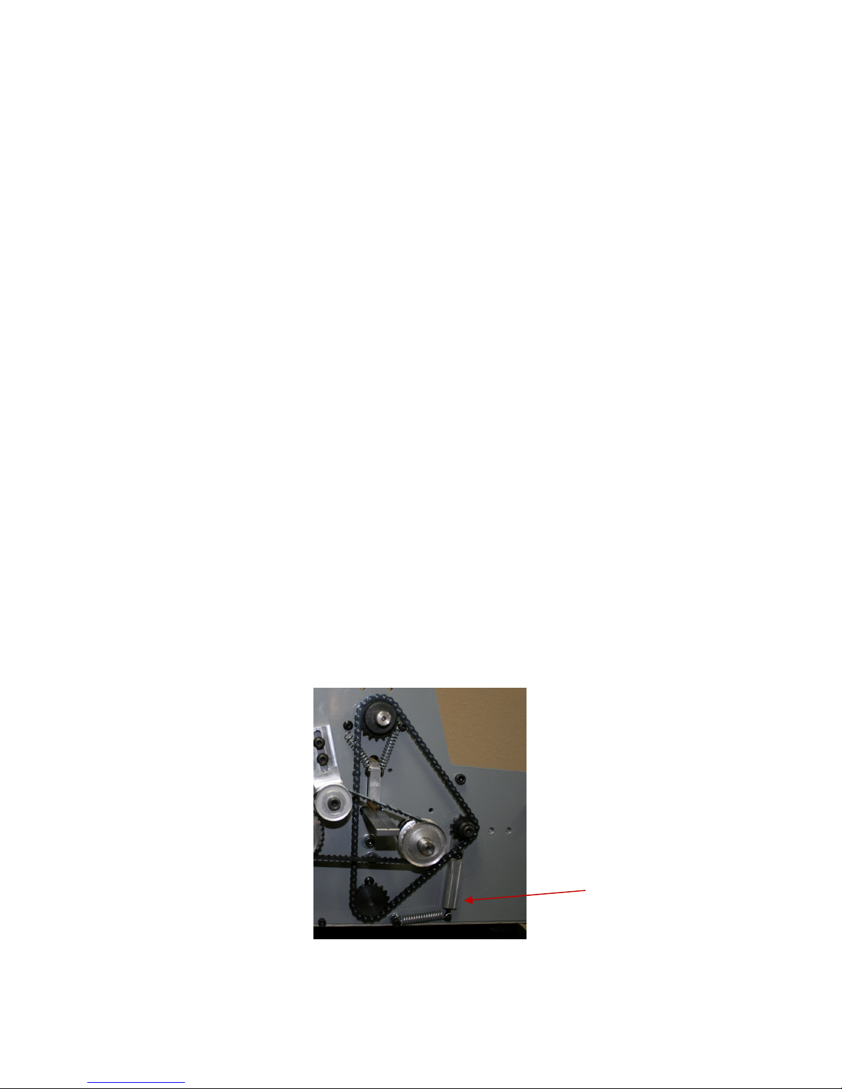
DRIVE CHAIN TENSION
The chain that drives the upper crease die in time will stretch. This is a common
occurrence in chains. The spring tensioner bracket will automatically adjust the tension.
It is important that this chain remain taught and free of any play. It is recommended to
check this periodically. If there is play in the chain drive, make sure the adjustment
spring is in the correct location.
13
Tensioner
Bracket
Page 18

PERF SHAFT & STRIKE PLATE
Loosen both screws
Loosen both
screws
A
B
A – Support Bar – F-0232 This is the shaft that the roller wheels
and perf score are mounted on.
B – Lower Sensor Eye Assy. – S-AAM-0230 Located in the platen strike plate, directly
below the upper sensor. These two must
align.
REMOVING THE PERF SHAFT
Loosen the operator side cover. Locate and remove the perf shaft lock collar.
Next, remove the non-operator side cover. Loosen both of the belt tensioner idler pully’s. You do
not need to remove these as loosening them will allow enough movement to free the pully’s of
the perf shaft. Slide the perf shaft out the pulley side.
It is only necessary to slide the shaft out about 6 to 8 inches. With the shaft slid to the side, you
can access the lower hubs and reconfigure them as needed to complete any job. After you have
configured the lower shaft, replace the shaft into its bearing and secure the shaft collar. The
shaft should not be able to
move side to side. With
both drive belts in
Position, re-tension the
belt idlers and tighten
while applying constant
firm pressure on the belts
by pushing down on the
tops of the brackets with
the large T-handle wrench
supplied. Replace covers.
Align upper assemblies
accordingly.
14
Page 19
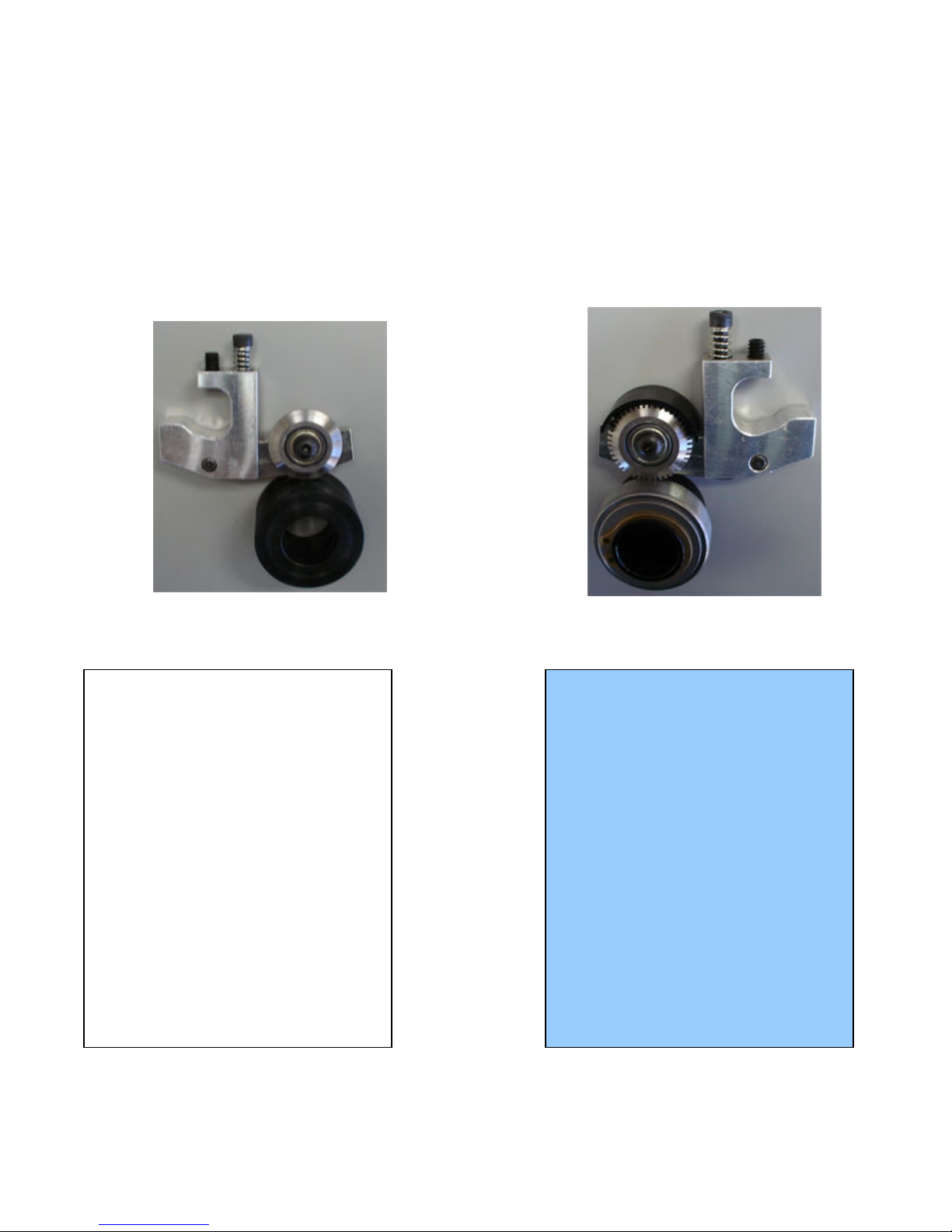
PERFORATING AND SCORING ASSEMBLIES
For removing and old blade and attaching a new blade to the pressure adjust mounting
bracket, remove the (1) button head cap screw. BE SURE TO TIGHTEN THE SET
SCREW SECURELY TO THE BAR. Once you have the upper and lower perf assemblies
in place, you can tighten the half dog screw.
Complete: #S-APP-0129 Complete: #S-APP-0139
Part No. Description
H-0215 Screw-10-32x1/2” button head
socket
H-0250 Screw-10-32x 1 1/2”socket cap
H-0270 Screw-1/4”-20x1/4” socket set
H-0275 Screw-1/4-20x1/4” socket set
H-0278 Screw-1/4-20x1/4” socket half
dog
H-0456 Washer – flat .20
H-0580 Compression spring 1 ½”
F-0403 315-s40 silicone gripper wheel
F-0425 Forward roller mount ap-app
F-0430 Forward roller (rubber only)
S-APP-0116 Roller wheel assembly
S-APP-0131 Score blade assembly
S-APP-0141 Perf blade assembly
S-APP-0132 Lower score hub assy.Hub ap
S-APP-0142 Lower perf assy. Hub app
S-APP-0622 Bracket-perf/score pres,adj.
assy
15
Roller Assembly Diagram
Complete: # S-CRZ-0000
Page 20
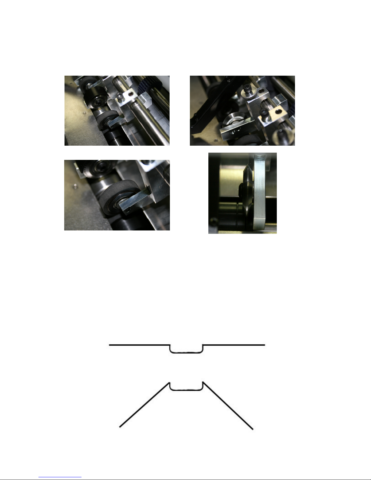
GRIPPER WHEEL PERF-SCORE MOUNTING
Rubber Grip Wheel Position
Score Wheel
Position your score blade as desired. Scores should be made so that the blade runs on
the side of the sheet that will be on the outside of the finished fold. Scores may be
made on the EZ CREASER in three different ways using the different grooves on the
lower score assembly.
FOLDING DIRECTION OF PAPER
There is a correct and incorrect way to fold a creased paper. Following the diagram
below will show you the correct direction the paper should be folded.
16
Page 21
A
B
C
D
E
H
I
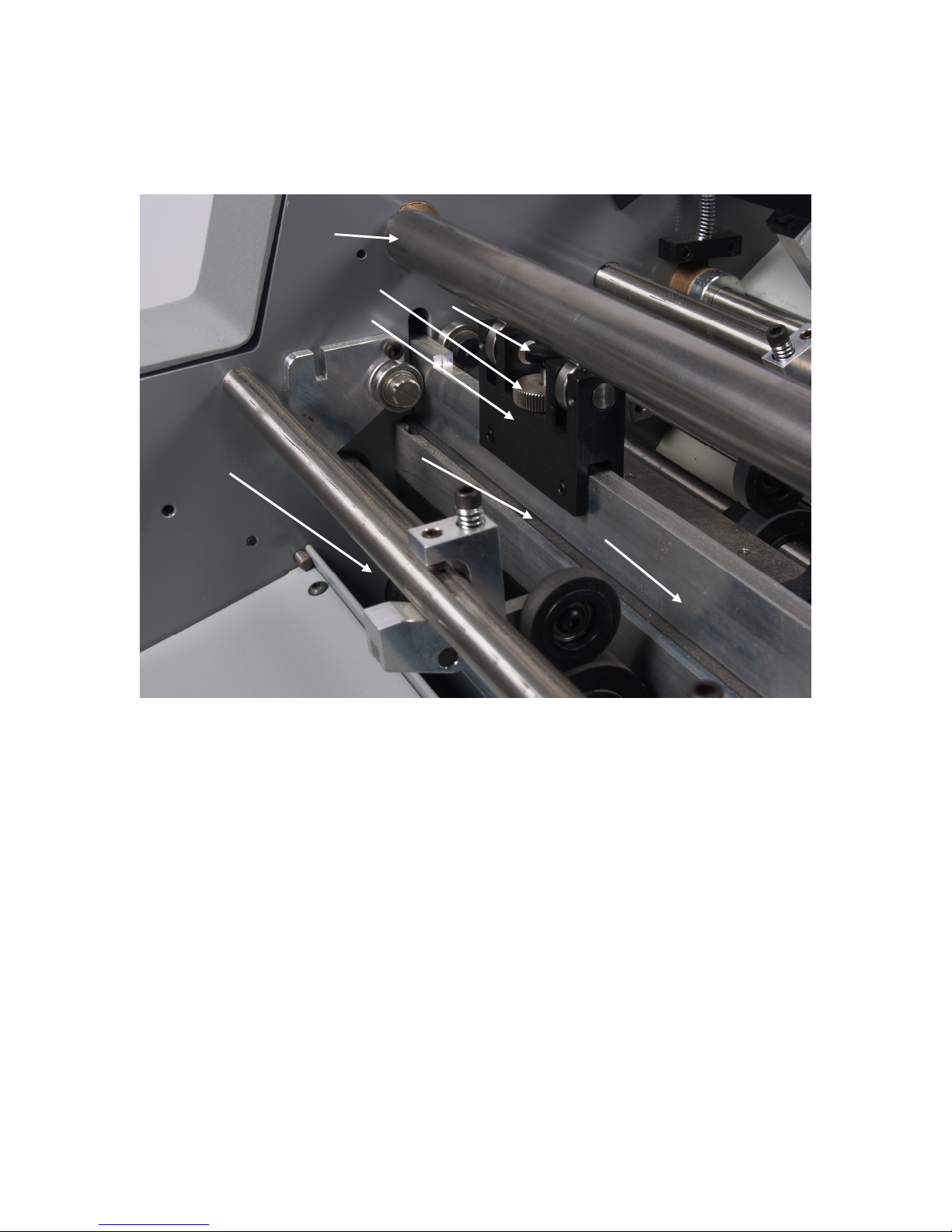
RAC System (Rotary Actuated Creasing) Assembly
Component ID
A. RAC drive motor
B. Eccentric Drive Shaft
C. Upper crease die
D. Pressure Adjust bearing blocks (RAC Rollers)
E. Lower crease die
F. Drive chain & tensioner SEE DRIVE CHAIN TENSIONER ON PAGE 13
G. Return springs SEE SERVICE DIAGRAM A ON PAGE 21
H. Compression bracket RAC locknut F-2640
I. Compression Bracket Adjust Screw Assy
17
Page 22
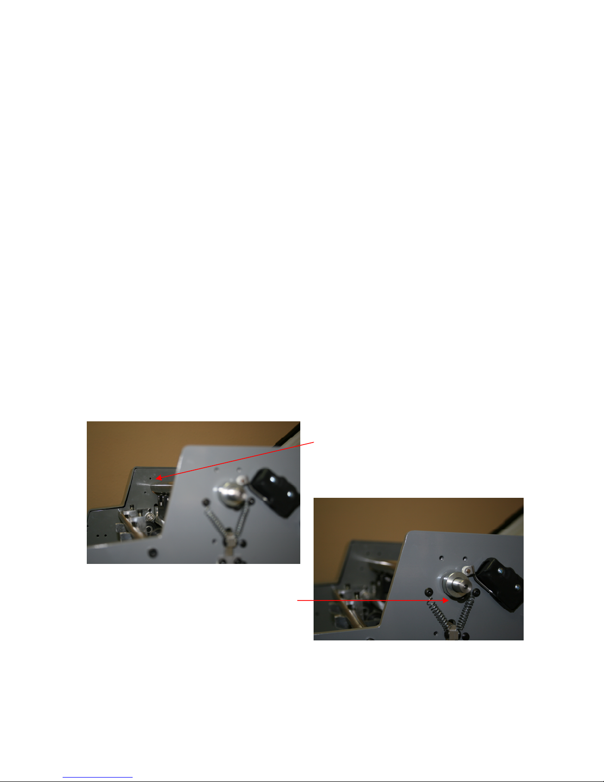
To ensure proper adjustment make
Use the button head adjustm
ent
ADJUSTING THE RAC ROLLERS
The RAC rollers are set from the factory and it is NOT recommended to make any
adjustments to this without consulting with Count’s tech-support department.
Should an adjustment be necessary, please follow the steps below.
Loosen the small bearing block lock screws. This allows very slight adjustments of the
bearing block to be made by loosening the thumb lock and turning the height
adjustment screw in the middle of the bearing block. This is a very fine thread and is
capable of making very slight adjustments. Turning the adjustment screw clockwise will
increase the bar pressure, as counterclockwise will decrease the pressure. Once the
adjustment to the bar has been made, slightly tighten the thumb lock and re set the
block set-screws.
ADJUSTING RAC TOP DEAD CENTER
The top dead center of the RAC will need to be adjusted from time to time. To do this
turn the machine off, remove the operator side cover, and manually rotate the eccentric
shaft to the top dead center. Then locate the adjusting shaft collar on the end of the
eccentric on the operators side and take a 5/32 allen wrench and loosen the button
head screw and rotate it to the 6 o’clock position. This will ensure proper alignment of
the crease bar.
screw to the 6 o’clock position.
sure the eccentric drive shaft is at top
dead center.
18
Page 23

CHANGING THE LOWER CREASE DIE
The Lower crease die can easily be changed to accommodate thicker stocks by removing
the non-operator side cover, slide the bar out and flip it over to use the wider die
channel. Please note, custom die’s are available upon request.
19
Page 24

TROUBLE SHOOTING
• POWER DOES NOT TURN ON
1. Check circuit breaker on rear panel.
2. Check outlet for power.
• POWER TURNS ON (FAN ON) BUT MICROPROCESSOR DOES NOT LIGHT UP
1. Check ¼ amp & 3 amp fuse on rear panel.
2. Check connector from control board to machine.
• MICROPROCESSOR COMES ON BUT DISPLAY IS SCRAMBLED
1. Poor Connection on or to control board.
2. Turn power off then turn back on. If display remains scrambled, contact Count
Service Department.
• TRANSPORT “LOCKS UP” AFTER CREASING
1. Check pulleys to make sure they are securely tightened on shafts.
2. Check to see that the transport turns freely (oil when necessary).
3. Possible damage to microprocessor.
• FEED TABLE NOT FEEDING CORRECTLY
1. Clean feed wheel rollers.
2. Feed wheels do not have equal pressure on them, check adjustment.
3. Contact strip is worn and will not gap the stack.
• SHEETS NOT FEEDING STRAIGHT
1. Unequal feed wheel pressure.
2. Align feed rails “check for squareness”. This can be checked by the lead edge
of the paper feeding into the machine should line up with the front edge of the
feed plate.
3. Not enough pressure on forwarding rollers.
4. Clean ALL rubber rollers.
• PERF IS NOT STRAIGHT
1. Check for equal pressure on all grip wheels and that none are hanging up.
2. Recheck all steps under (SHEET NOT FEEDING STRAIGHT)
• PERFORATION IS NOT CLEAN OR CUTS SHEETS
1. Not enough pressure on perf wheel.
2. Perf blade is worn.
• CREASE NOT REGISTERING ON SHEET
1. Clean all Rubber Rollers
2. Check pressure on grip wheels. If these are not down firmly, your registration
will be off.
3. Check all pulleys to make sure they are securely tensioned on shafts.
4. Check to see that machine transport turns freely.
• CREASE APPEARS WEAK
1. Crease bar not level.
2. Not enough pressure, adjust RAC rollers with height adjustment screw.
3. Too much pressure, motor cannot make full stroke.
4. Crease bar not tightened properly on bracket.
• CREASE BAR DOES NOT ROTATE
1. Crease bar set too low, cannot make full stroke.
2. Crease bar is dirty. Clean with damp cloth and wipe clean.
3. Verify red and green lights on creaser board are firing on and off.
20
Page 25
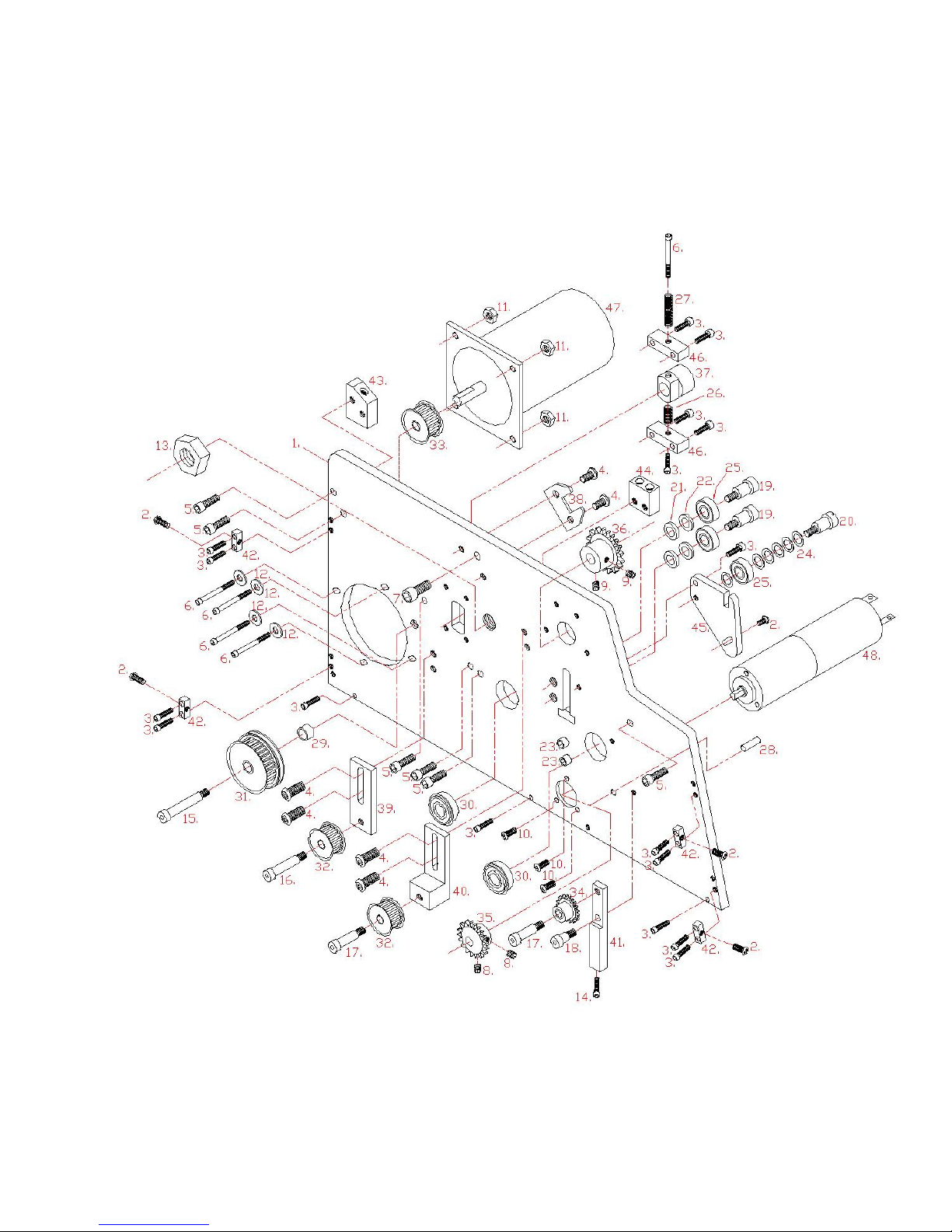
SERVICE DIAGRAM A
EZ CREASER SIDE FRAME LEFT (NON OPERATOR)
Paper folding direction.
21
Page 26

SERVICE DIAGRAM A
Parts Description List
ITEM NUMBER PART NUMBER DESCRIPTION
1 F-2637 FRAME NON OPERATOR - LEFT - CREASER
2 H-0215 SCREW, 10-32X1/2" BUTTON HEAD CAP SCREW
3 H-0235 SCREW, 10-32 X 5/8" SOCKET CAP
4 H-0285 SCREW, 1/4-20X1/2" BTN HD SOC CAP
5 H-0315 SCREW, 1/4-20X3/4" SOCKET CAP
6 H-0250 SCREW, 10-32X1-1/2" SOCKET CAP
7 H-0361 SCREW, 5/16-18X3/4" SOCKET CAP
8 H-0204 SCREW, 10-32 X 3/16" SOCKET SET
9 H-0270 SCREW, 1/4-20 X 1/4" SOCKET SET
10 H-0199 SCREW, 10-16 X 1/2" PHIL PAND HEAD - BLK.
11 H-0410
12 H-0455 WASHER #10 FLAT
13 H-0425 NUT, 5/8" HEX
14 H-0245 SCREW, 10-32 X 1" SOCKET CAP
15 H-1543 SCREW, 3/8 X 1-1/2" SOCKET SHOULDER BOLT
16 H-1665 SCREW, 5/16 X 1" SOCKET SHOULDER BOLT
17 H-0380 SCREW, 5/16X3/4" SHOULDER SOCKET CAP
18 H-0375 SCREW, 1/4X1/4" SHOULDER SOCKET CAP
19 H-0386 SCREW, 3/8 X 1/2" SHOULDER SCS.
20 H-1668 SCREW, 3/3 X 3/8 SHOULDER SLOT
21 H-1669 WASHER, 3/8 ID X .125 THICK
22 H-1670 WASHER, 3/8 ID X .095 THICK
23 H-0320 SCREW, 1/4-20X1" SOCKET CAP
24 H-0480 WASHER, FLAT BURR WHEEL
25 H-0669 BEARING, ROLLER .375ID X .875OD X .280W.
26 H-0570 SPRING COMPRESSION - 3/4"
27 H-0580 SPRING, COMPRESSION 1-1/2"
28 H-1672 DOWEL PIN .252 RECEIVING TRAY SUPPORT
29 H-1660 BEARING, BRONZE 3/8ID X 1/2OD X 1/4W.
30 H-0679 BEARING, ROLLER 1/2"I.D. FLANGED
31 S-CRZ-0013 IDLER DRIVE PULLEY ASSY - FEED DRIVE
32 S-APP-0646 IDLER PULLEY ASSY 16T.
33 H-0706 PULLEY TIMMING 1/5 PITCH 18 TOOTH
34 S-CRZ-0009 SPROCKET, #25 12T.
35 HF-0798 MOTOR SPROCKET 17T. #25 W/ METRIC BORE
36 H-0802 ECCENTRIC SHAFT SPROCKET #25 18T.
37 F-2271 BEARING, BRONZE 1 X .5 X 1" MODIFIED.
38 FS-315 TIE BAR LOCK
39 F-0542 BRACKET, IDLER 1/4" - APP
40 F-0541 BRACKET, IDLER 1" - APP
41 F-2654 BRACKET, CHAIN TENSIONER
42 F-0808 SIDE COVER MOUNT BLOCK-APP
43 F-2275 PLATE MOUNT RR - T.F. AP+
44 F-0534 FEED PLATE MOUNT FRONT-APP
45 F-2649 BEARING ADJUST BRACKET - CREASER
46 F-2272 BRACKET, FEEDER SHAFT ADJUST.
47 E-1227 MOTOR STEPPER
48 E-1241 MOTOR CREASER - DRIVE BAR
HEX NUT 10-32 LOCK-KEPNUT
22
Page 27
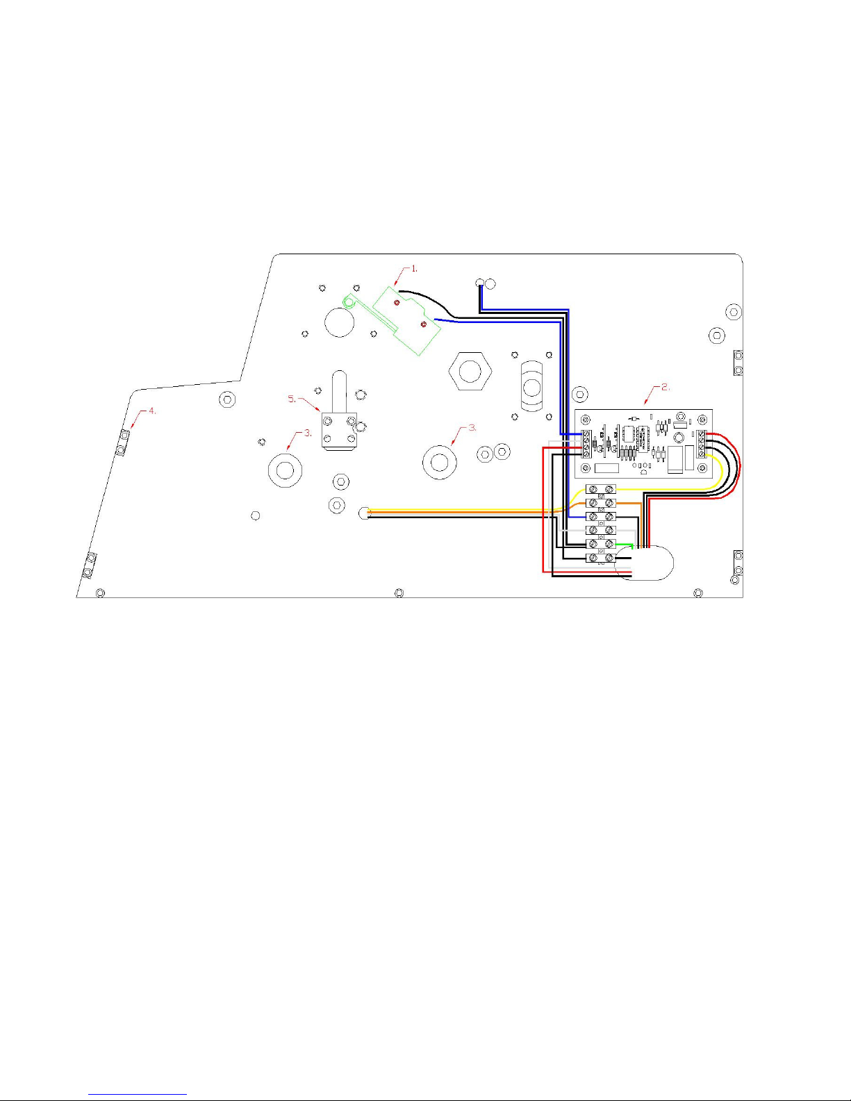
SERVICE DIAGRAM B
EZ CREASER SIDE FRAME RIGHT (OPERATOR)
ITEM NUMBER PART NUMBER DESCRIPTION
1 S-CRZ-0018 SWITCH, - ASSY
2 E-1240 CREASER BOARD
3 H-0635 COLLAR, SHAFT 1/2"
4 F-0808 SIDE COVER MOUNT BLOCK-APP
5 F-2646 CREASER BAR BLOCK PLATE
23
Page 28
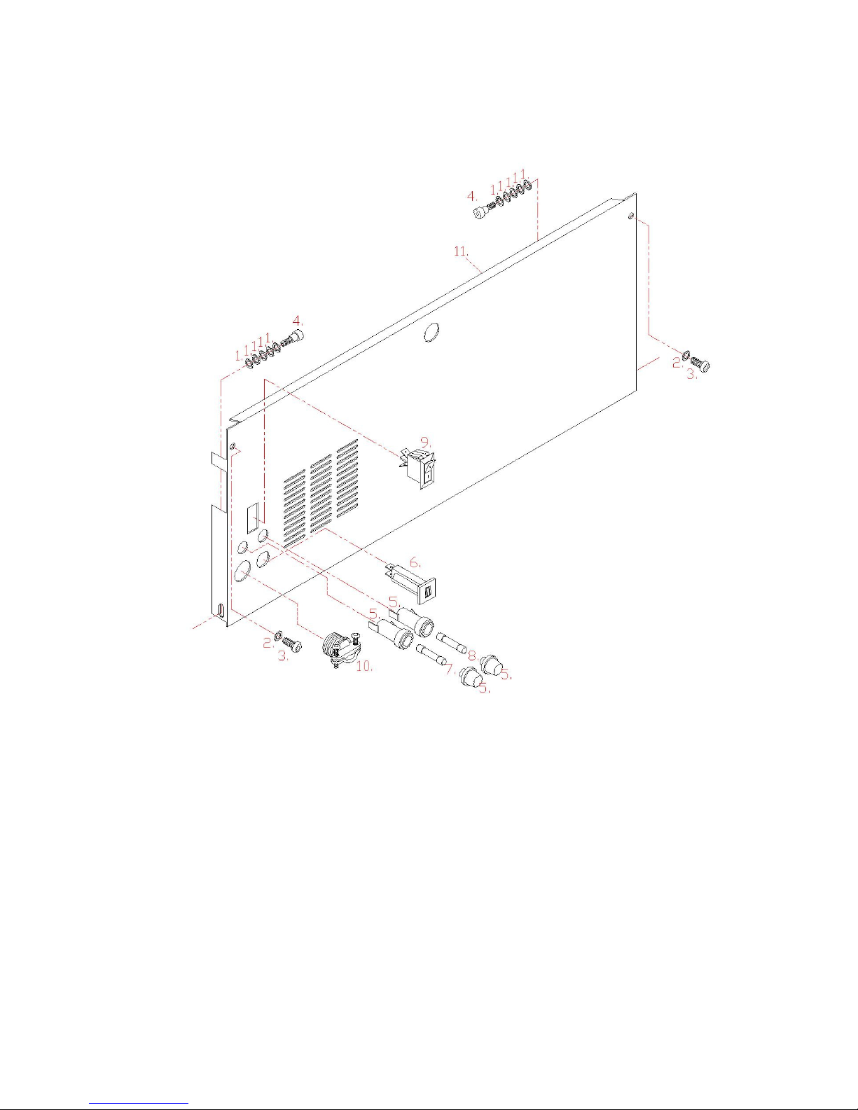
SERVICE DIAGRAM C
EZ CREASER BASE ASSEMBLY
ITEM NUMBER PART NUMBER DESCRIPTION
1 H-0466 WASHER, 1/4I.D. 3/8O.D. 1/32 THICK
2 H-0465 WASHER, 1/4" NYLON
3 H-0285 SCREW, 1/4-20X1/2" BUTTON HEAD SOCKET CAP
4 H-0375 SCREW, 1/4X1/4" SHOULDER SOCKET CAP
5 E-0851 FUSEHOLDER-QUICK CONNECT
6 E-0705 CIRCUIT BREAKER 3 AMP
7 E-0795 FUSE 313.250 1/4AMP
8 E-0790 FUSE 313003 3AMP
9 E-0755 SWITCH ON/OFF ROCKER
10 H-0856 STRAIN RELIEF - STEEL
11 FS-065 REAR PANEL APP
24
 Loading...