

Coulter STKS Troubleshooting
COULTER®STKS Analyzer with Reticulocyte Analysis
Special Procedures
and Troubleshooting
COULTER
STKS
PN 4237187B (March 1995)
COULTER CORPORATION
Miami, Florida 33196

READ ALL PRODUCT MANUALS AND CONSULT WITH COULTER-TRAINED PERSONNEL BEFORE
ATTEMPTING TO OPERATE INSTRUMENT
HAZARDS AND OPERATIONAL PRECAUTIONS AND LIMITATIONS
WARNINGS, CAUTIONS, and IMPORTANTS alert you as follows:
WARNING - Might cause injury.
CAUTION - Might cause damage to the instrument.
IMPORTANT - Might cause misleading results.
CAUTION|
|
System integrity might be compromised and operational errors might occur if:|
|
• Thisequipmentisusedinamannerotherthanspecified.Operatetheinstrumentasinstructedinthe|
Product Manuals.|
|
• You introduced software that is not authorized by Coulter into your computer. Only operate your|
system’s computer with software authorized by Coulter.|
Coulter Corporation urges its customers to comply with all national health and safety standards such as
the use of barrier protection. This may include, but it is not limited to, protective eye wear, gloves, and
suitable laboratory attire when operating or maintaining this or any other automated laboratory analyzer.
In the USA, for Service call Coulter Customer Operations 1-800-526-7694.

1 GENERAL SERVICE AND MAINTENANCE, 1
1.1 LASER MAINTENANCE, 1
1.2 GENERAL PROCEDURES, 1
Power Down, 3
Power Up, 3
Optimize the Disk, 3
Daily, 4
Weekly, 4
Monthly, 4
Set Screen Saver, 5
Position Rocker Bed, 6
Diluter F Key Functions, 6
1.3 COMPONENTS, 10
Cylinders (CL), 11
Manifolds (MF), 11
Pumps (PM), 12
Vacuum Chambers (VC), 12
Pinch Valve (VL) Functions, 13
Solenoid (SL) Functions, 17
CONTENTS
2 CALIBRATION, 21
2.1 GENERAL INFORMATION, 21
2.2 PRECALIBRATION STEPS, 22
Reproducibility Check, CBC/Diff, 23
Sample Requirements, 23
Procedure, Primary Mode, 24
Carryover Check, 26
Sample Requirements, 26
Procedure, 26
2.3 CBC CALIBRATION WITH S-CAL CALIBRATOR, 28
Calibration Summary, 28
2.4 CALIBRATE CBC PARAMETERS WITH WHOLE BLOOD, 37
3 CLEANING PROCEDURES, 39
3.1 CLEAN BLOOD SAMPLING VALVE (BSV), 39
Procedure A, Rinse the BSV Outside Sections, 39
PN 4237187A (November 1993) i

CONTENTS
Procedure B, Remove and Clean the BSV Sections, 40
3.2 CLEAN APERTURES, 44
Procedure A, Zap the Apertures, 44
Procedure B, Bleach the Apertures, 44
Procedure C, Clean the Aperture Baths, 49
Procedure D, Clogged Apertures, 52
Procedure E, Clear Flow Cell, 53
3.3 TRANSPORT SYSTEM, 54
Clean Rinse Trough, 54
Clean Cassettes, 56
Clean Stripper Plate, 56
Clean Rocker Bed Belt, 56
3.4 OTHER COMPONENTS, 56
Clean Air Filters, 57
Clean Vacuum Isolator Chamber (VIC), 58
Clean Waste Chamber, 60
Clean Vacuum Trap Bottle, 61
Bleach RBC Internal Electrode, 62
Drain Overflow Chamber, 64
Clean Drip Plate, 64
4 REPLACE/ADJUST PROCEDURES, 67
4.1 REPLACE REAGENTS, 67
4.2 REPLACE WASTE CONTAINER, 68
4.3 REPLACE FUSES, 69
4.4 REPLACE APERTURE BATHS, 70
4.5 REPLACE O-RINGS, 71
4.6 REPLACE CHECK VALVES, 72
4.7 REPLACE AIR FILTERS, 73
4.8 REPLACE CHOKES, 73
4.9 ATTACH TUBING TO A FITTING, 73
4.10 REPLACE PIERCING NEEDLE, 73
Decontaminate Needle, 73
ii PN 4237187A (November 1993)

Replace Needle, 74
4.11 REPLACE CASSETTE SPRING CLIP, 76
4.12 REPLACE CASSETTE LABELS, 77
4.13 CHANGE RINSE TROUGH PAD, 77
4.14 ADJUST HEMOGLOBIN LAMP VOLTAGE, 78
4.15 ADJUST TUBE DETECTOR, 79
5 TROUBLESHOOTING, 81
5.1 ANALYZER RESET PROCEDURE, 81
5.2 DMS RESET PROCEDURE, 83
DMS Not Working, 83
Printer Not Ready, 84
Lost Clusters, 84
CONTENTS
5.3 RAMP AND PRECISION TESTS, 85
5.4 RETIC REPRODUCIBILITY CHECK, 85
5.5 PROLONGED SHUTDOWN PROCEDURE, 87
5.6 ANALYZER CLOCK STOPPED, 87
5.7 ANALYZER ALERT MESSAGES, 89
5.8 DILUTER DIAGNOSTIC MESSAGES, 100
5.9 DMS ERROR MESSAGES, 107
5.10 GRAPHIC/LASER PRINTER PRECAUTIONS, 113
INDEX, 119
ILLUSTRATIONS
1 Diluter Front Panel, 2
2 Screen Saver Setup, 6
3 Pinch Valve and Solenoid Locations, 20
4 Reproducibility, 25
PN 4237187B (March 1995) iii

CONTENTS
5 Carryover Acceptable Screen, 28
6 CBC Calibration Screen, 30
7 Calibration Criteria Flowchart, 33
8 Blood Sampling Valve (BSV), 41
9 RBC and WBC Aperture Baths, 45
10 Aperture Bath, Blocks and Housings, 51
11 Rinse Trough, 55
12 Location of Air Filters, 57
13 Clean VIC, 59
14 Drip Plate, 64
15 Replace Piercing Needle, 75
16 Tube Detector Adjustment, 80
17 Reset Button Location, 82
18 Retic Reproducibility, 86
TABLES
1 Diluter F Key Functions, 7
2 Cylinders, 11
3 Manifolds, 11
4 Pumps, 12
5 Vacuum Chambers, 12
6 Pinch Valves, 13
7 Solenoids, 17
8 Open-Fuse Indications, 69
9 Analyzer ALERT Messages, 89
10 Diluter Diagnostic Messages, 101
11 DMS Error Messages, 107
iv PN 4237187B (March 1995)

1.1 LASER MAINTENANCE
All service and maintenance of the laser module must be done by trained
Coulter personnel. Removal of the module must be performed only by a
Coulter Representative.
1.2 GENERAL PROCEDURES
GENERAL SERVICE AND MAINTENANCE 1
1
GENERAL
WARNING
Do not try to remove the laser module from the Diluter.
IMPORTANT
If a power failure or reset occurs during a cycle, after power up, press
PRIME APERT before cycling samples.
This section details the cleaning, replacement, and adjustment
procedures that are your responsibility. General operations that may
apply to numerous procedures are described below. They include:
Power Down
Power Up
Optimize the Disk
Set Screen Saver
Position Rocker Bed
Diluter
Coulter recommends a Preventive Maintenance Inspection (PMI) once a
year by a Coulter Service Representative.
Figure 1 illustrates component location on the Diluter front panel.
F Key Functions
PN 4237187A (November 1993) 1

GENERAL SERVICE AND MAINTENANCE
A
GENERAL
67
1
8
9
VL30 VL31 VL32 VL33 VL34 VL35 VL36 VL37
VL19
10
11
12
GA1
VC15
RG2
PM8
VL43
VL38
VL40
VL44
PM7
VL20 VL18 VL22
VL47
VL46
VL48
VL50
SOL47
VC14
VL49
13
7187002
PM10
PM9
14
17. HGB CUVETTE HOLDER
18. BATH OVERFLOW CHAMBER (VC10)
19. NEEDLE-RINSE PUMP (PM1)
20. WBC DILUENT DISPENSER (PM3)
21. RINSE MIX CHAMBER PUMP (PM11)
22. 1mL BACKWASH PUMP (PM6)
23. RBC DILUENT DISPENSER (PM2)
17 16 15
VL14 VL15 VL16
VL13
VL4 VL7
12345
VL3
VL2
VL1
PM4
VL6
VL5
9. ELECTRONIC MANOMETER WINDOW
10. MANOMETER RANGE SCALE
11. CBC LYTIC REAGENT PUMP (PM8)
12. SHEATH TANK (VC15)
13. 5mL CLEANING AGENT PUMP (PM10)
14. 5mL HGB PUMP (PM9)
15. FOAM TRAP (VC14)
16. WASTE CHAMBER (VC11)
SOL1
SOL5
PM11
1. ERYTHROLYSE II PUMP (PM4)
2. RBC BATH (VC2)
3. VACUUM ISOLATOR (VC1)
4. WBC BATH (VC3)
5. STABILYSE PUMP (PM12)
6. CBC LYTIC REAGENT PUMP (PM7)
7. MANOMETER REGULATOR
8. SHEATH FLOW RESTRICTOR
PM6
22 21 20 19 18
PM = PUMP
PM1
VL11VL10
PM3
VL12
PM2
Figure 1 Diluter Front Panel
VC = VACUUM CHAMBER
23
2 PN 4237187A (November 1993)

GENERAL PROCEDURES
Power Down
1. Turn off the Graphic Printer.
2. Turn off the Ticket Printer.
3. Turn off the DMS.
4. Press
5. Turn off the MAIN POWER circuit breaker on the Power Supply.
6. Unplug the primary power cord from the wall outlet.
7. Verify that the power is disconnected:
8. Turn off the MAIN POWER circuit breaker.
POWER OFF on the Diluter keypad.
a. Turn on the MAIN POWER circuit breaker.
b. Check the front panel of the Power Supply and be sure there
are no lamps lighted. If any lamp lights, the power is still
connected; you must repeat steps 5, 6 and 7.
1
GENERAL
Power Up
Optimize the Disk
1. Plug the primary power cord into the wall outlet.
2. Turn on the MAIN POWER circuit breaker on the Power Supply.
3. Press
4. Turn on the DMS.
5. Turn on the Ticket Printer.
6. Turn on the Graphic Printer.
This system is equipped with the OPTune™ utility, a software utility
that optimizes the hard drive on your DMS. Optimizing organizes files
on your hard drive so that the DMS is faster and more efficient. The
OPTune utility runs when you turn on the DMS and when you reset the
DMS.
POWER ON on the Diluter keypad.
PN 4237187A (November 1993) 3

GENERAL SERVICE AND MAINTENANCE
GENERAL
1
The OPTune utility performs three types of optimization: daily, weekly
and monthly. The type it uses depends on how long it has been since the
last optimization.
Daily
The fastest method, this type leaves each file
• 100% defragmented
• sorted in ascending order by name
• in contiguous order
Weekly
Takes about 50% longer than the daily method. Does everything the
daily method does, plus it optimizes in the packed mode. It arranges the
files on your hard drive so that they are end-to-end, with no space
between them. Thus, new files are likely to be written to disk without
being fragmented.
Monthly
The most thorough method. Does everything the weekly method does,
plus it physically arranges files on the disk in the same order as the
sorted directory entries. This method takes longer, but increases
efficiency when accessing many files in sequential order.
The OPTune utility initially takes about 45 minutes to an hour to
optimize a 240MB hard drive. After that, daily optimization takes about
30 to 40 seconds. The OPTune utility reorganizes only those files that
need it; it does not reoptimize unnecessarily.
You can bypass the OPTune utility process by pressing while the
OPTune utility screen is in view. When the message Do you want to stop?
[Y/N] appears, press . This message appears: User terminated Verify.
The optimizing process stops and the system goes into the DMS
program.
If there is a hard disk failure during the optimization process, for
example lost clusters or cross-linked files, the OPTune utility prompts
you to continue. Answer Yes to go on with the process. However, if this
happens more than once a week, record the incident in your DMS
maintenance log or your logbook and call Coulter Customer Operations.
4 PN 4237187A (November 1993)

GENERAL PROCEDURES
If you always leave your system turned on, we recommend that you run
the OPTune utility at least once a week, using one of these two options:
1
Option A
1. Turn off the Graphic Printer.
2. Turn off the DMS.
3. Wait at least 15 seconds.
4. Turn on the DMS.
5. Turn on the Graphic Printer.
Option B
Select
Special Functions
Sample Analysis Set up
Reset DMS
When you reset the DMS or turn it off then back on, these functions
default to these conditions:
GENERAL
Set Screen Saver
• Data Base storage: ON (DB↑)
• XB: ON (XB↑)
• AutoPrint: NONE (PR↓)
• AutoTransmit: OFF (HC↓)
Reset these options as needed according to your laboratory’s protocol.
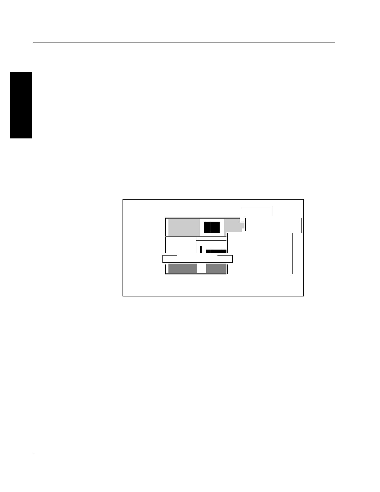
The screen saver function makes the screen go blank when it is not being
used. Figure 2 illustrates the Setup window. Select
Special Functions
Set Up
System Set Up
Screen Saver Time Out
PN 4237187A (November 1993) 5
GENERAL SERVICE AND MAINTENANCE
GENERAL
1
Set the time, in minutes, for the length of time to elapse before the screen
goes blank. You can enter from 0 to 99 minutes.
• A number from 1 to 99 means that, if there is no keystroke in that
many minutes, the screen goes blank. The screen also goes blank
when the compressor times out.
The screen turns back on under these conditions:
- The DMS receives a sample run.
- You press a key on the DMS keyboard. The DMS executes the
keystroke as it applied to the screen before it went blank.
• Zero means the screen saver will not be activated.
Sample Analysis Controls Start Up Special Functions
DMS 2A Diagnostics
Control set up
Sample analysis set up
C System set up|
Screen Saver Setup anguage
Screen Saver Delay: 0 Minutes QAP ID #|
Change Supervisor Password
Screen Saver Time Out|
(931951) COPYRIGHT 1989-1993 COULTER CORPORATION, ALL RIGHTS RESERVED
F1-Help F3-Error Log F5-Other F9-Main menu F10-Previous menu
07/14/93 17:17 OPR DMS↑ PR↓ TK↓ HC↓ DB↑ XB↓ WL↑ HWL↓ QC↑ 59
CBC/Diff/Retic
Set Up|
Shift
Reagents
Institution
Communication def
Electronic reference
atabase
Figure 2 Screen Saver Setup
Position Rocker Bed
When the compressor is off, the rocker bed is not locked in position and
can be tilted easily.
Diluter F Key Functions
The Diluter F key functions are listed in Table 1. To select these
functions, press
6 PN 4237187A (November 1993)
F X X ENTER where XX is the function number.

GENERAL PROCEDURES
During these functions, a related message appears on the Diluter keypad;
when the routine is finished, the message returns to the function
number.
For example, when you select F01, the burn circuit activates and the
message appears;
CLEAN APERTURES
after which the message returns to:
FUNCTION = 01
1
GENERAL
To repeat the function, press
Table 1 Diluter F Key Functions
Function Message Description
F01
F02
F03
F04
F05
F06
CLEAN APERTURES
PRIME CBC LYSE
RBC AND WBC MIX
DILUENT DISPENSE
SOLENOID XX
RELEASE B.S.V.
The burn circuit activates. This function applies current across
the apertures to "burn" protein or debris off the apertures.
The following sequence occurs twice:
• Drains both baths then dispenses CBC lytic reagent into the
WBC bath three times to prime the lyse line.
• The WBC bath drains and the cycle repeats.
• It then fills both baths with diluent and primes the apertures.
Causes mixing bubbles to enter both the RBC and WBC baths.
Dispenses 1 mL of diluent through the Secondary mode
aspirator tip.
Use to manually activate individual solenoids (see Table 7).
Enter the desired solenoid number (for numbers less than 10,
enter a leading zero), and press ENTER.
• Drains the baths
• Bleeds off pressure
• Rotates the BSV back and forth five times
ENTER. To exit the function, press STOP.
Use to check BSV function, free a stuck valve, or when cleaning
the BSV to ease removal. Press STOP twice to exit the function.
This function does not refill the baths; use RINSE to refill them
with diluent.
continued
PN 4237187A (November 1993) 7

GENERAL SERVICE AND MAINTENANCE
Table 1 Diluter F Key Functions
Function Message Description
continued
F07
GENERAL
BARCODE READ RATE
TEST
Checks the bar-code read rate on the cassette bar-code label,
and on the four types of tube bar-code labels.
1
F08
F09
PRIME SWEEP FLOW
ZAP APERTURES
1. Enable the bar-code reader.
2. Remove the cap-piercing needle so that extensive piercings
do not cause a plugged needle.
3. Place a cassette of bar-code labeled tubes on the rocker
bed.
4. Select the function, then the following appears on the
Diluter display:
A00B00C00D00E00
A represents Interleaved 2-of-5
B represents Code 39®Bar code
C represents Codabar
D represents the cassette label
E represents code 128
The cassette automatically moves to the piercing station
and the bar-code reader scans both the cassette and tube
labels. On the display, the appropriate category increments
by one each time a label from that category is read. Press
STOP twice to exit the function.
Primes the sweep-flow lines.
• Applies pressure behind the baths
• Drains and rinses the baths four times with cleaning agent
• Draws the cleaning agent behind the apertures
• Zaps the apertures 10 times
After this function is complete, you must execute the startup
cycle to purge the system of the cleaning agent.
F10
F11
F12
F13
RAISE NEEDLE
EXTENDED PRIME
EXTENDED CLEAR
PURGE MODE
Causes the piercing needle to rise and the rocker bed to lock in
the backward position. Press STOP twice to exit.
Pulls fluid through the apertures to the vacuum isolator chamber
for 60 seconds. Aperture current turns on and aperture lamp
intensity increases for viewing the aperture screen.
Clears the apertures for 60 seconds. Use to clear bleach.
Use to clear air bubbles or debris from the flow cell.
continued
8 PN 4237187A (November 1993)

GENERAL PROCEDURES
Table 1 Diluter F Key Functions
Function Message Description
continued
F14
F15
F16
F17
F20
F44
F45
PRIME PAK LYSE
PRIME PAK PRESRV
PRIME DILUENT
PRIME SCATTER PAK
FILL SHEATH TANK
CLEAR FLOW CELL 1
CLEAR FLOW CELL 2
Used to prime the diff lyse lines for troubleshooting. For Service
use only.
Used to prime the diff preservative reagent lines for
troubleshooting. For Service use only.
Use to prime diluent lines when you replace the diluent
container.
Use to prime the diff reagents when you replace the SCATTER
PAK.
Used to fill the sheath tank as needed. For Service use only.
What it does to flow cell
• purges it with cleaning agent
• turns on its aperture current
• applies low pressure to it
• alternately applies vacuum to the bottom
• checks it for a clog
• leaves it in diluent
See the Clear Flow Cell procedure for instructions on the use of
this function.
What it does to flow cell
• purges it with cleaning agent
• turns on its aperture current
• applies 30 psi to top of it
• alternately applies vacuum to the bottom
• checks it for a clog
• leaves it in diluent
1
GENERAL
See the Clear Flow Cell procedure for instructions on the use of
this function.
F46
CLEAR FLOW CELL 3
Use only if F44 and F45 fail to clear flow cell.
What it does to flow cell
• purges it with cleaning agent
• turns on its aperture current
• applies low pressure to it
• alternately applies vacuum to the bottom
• leaves it in cleaning agent
See the Clear Flow Cell procedure for instructions on the use of
this function.
continued
PN 4237187A (November 1993) 9

GENERAL SERVICE AND MAINTENANCE
Table 1 Diluter F Key Functions
Function Message Description
continued
F55
F56
GENERAL
F57
1
F95
F96
LATRON CONTROL
F55 = DIFF
F56 = RETIC
F57 = DIFF + RETIC
SOLENOIDS FREE
TUBE ADVANCE
Access this function before you aspirate LATRON primer and
control.
Do not use this function to aspirate anything except
LATRON control or LATRON primer. Other material can
cause damage to the system.
This function causes approximately 1.5 mL of primer or control to
be aspirated through the Secondary mode aspirate tip directly
into the flow cell.
Frees the pressure from all solenoids. Press STOP twice to exit.
Use when you adjust the tube detector; causes a cassette to
move through the piercing station one tube position at a time.
Press STOP to halt the advance and make adjustments, ENTER
to continue the advance and check alignment. Press STOP twice
to exit the function.
CAUTION
1.3 COMPONENTS
This section includes
List of Cylinders
List of Manifolds
List of Pumps
List of Vacuum Chambers
Pinch Valve Functions
Solenoid Functions
Summary of Pinch Valve/Solenoid/Component Relationships
10 PN 4237187A (November 1993)

COMPONENTS
Cylinders (CL)
Manifolds (MF)
Table 2 lists the cylinders and the components they operate.
Table 2 Cylinders
Cylinder Operates
CL1 BSV front
CL2 BSV back
CL3 needle
CL4 left lift
CL5 right lift
CL6 tube ram
CL7 bar-code reader
CL8 bed rocker
CL9 belt advance
CL10 stripper plate
1
GENERAL
Table 3 lists the Manifolds and their output.
Table 3 Manifolds
Manifold Output
MF1 5 psi, level sense switches
MF2 pneumatic/hydraulic source input to Diluter, waste
MF3 30 psi
MF4 vacuum
MF6 30 psi, solenoid (SL) manifold
MF7 5 psi
MF8 5 psi, mixing bubbles
MF9 30 psi
MF10 vacuum
MF11 30 psi, SL manifold
MF12 vacuum
MF13 30 psi, SL manifold
MF15 30 psi
PN 4237187A (November 1993) 11

GENERAL SERVICE AND MAINTENANCE
Pumps (PM)
Table 4 lists the pumps and what they operate.
GENERAL
1
Table 4 Pumps
Pump Operates
PM1 needle rinse, 0.77 mL
PM2 RBC diluent dispense, 10 mL
PM3 WBC diluent dispense, 6 mL
PM4 5 diff lyse, 0.536 mL
PM6 backwash, 1 mL
PM7 3 diff lyse, 0.52 mL
PM8 3 diff lyse, 0.52 mL
PM9 Hgb blank, 5 mL
PM10 cleaning agent, 5 mL
PM11 rinse, 1 mL
PM12 leukocyte preservative, 0.193 mL
PM13 Primary mode aspiration, 0.250 mL
PM14 Secondary mode aspiration, 0.150 mL
Vacuum Chambers (VC)
Table 5 lists the vacuum chambers and the components they control.
Table 5 Vacuum Chambers
Vacuum Chamber Controls
VC1 vacuum isolator (VIC)
VC2 RBC bath
VC3 WBC bath
VC4 RBC bath aperture 1
VC5 RBC bath aperture 2
VC6 RBC bath aperture 3
VC7 WBC bath aperture 1
continued
12 PN 4237187A (November 1993)

COMPONENTS
Table 5 Vacuum Chambers
Vacuum Chamber Controls
continued
VC8 WBC bath aperture 2
VC9 WBC bath aperture 3
VC10 bath overflow
VC11 waste chamber (Diluter)
VC13 waste chamber (Diff)
VC14 foam trap
VC15 sheath tank
VC16 sheath flow
VC17 vacuum tank
VC18 flow cell
VC19 mixing chamber
VC20 foam trap
1
GENERAL
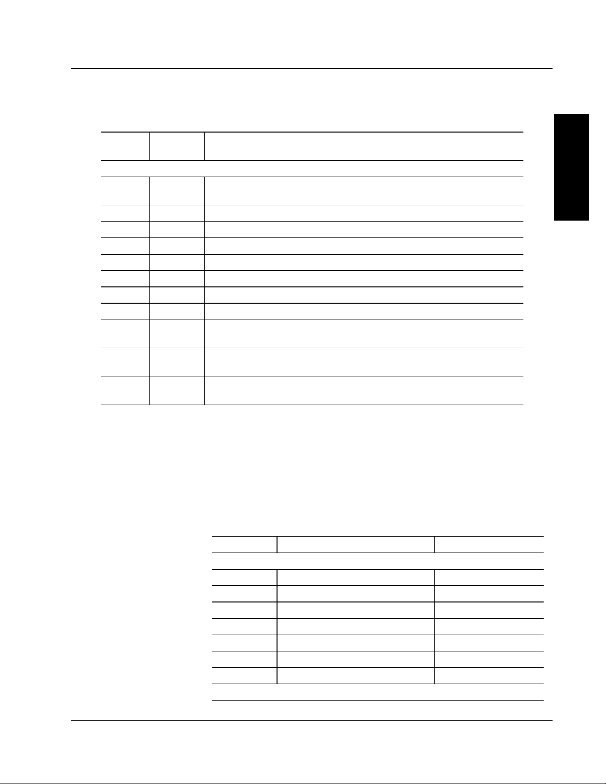
Pinch Valve (VL) Functions
Table 6 lists the pinch valves sequentially, shows which solenoid (SL)
controls the pinch valve, and gives each valve’s function. See Figure 3 for
most locations.
Legend: NC = Normally Closed
NO = Normally Open
NA = Normally Activated
Table 6 Pinch Valves
Pinch
Valve Solenoid Pinch Valve Function
VL1 SL18 NC path from RBC diluent dispenser to BSV rear section, port 9
NO path from RBC diluent dispenser to BSV rear section, port 10
VL2 SL18 NC path from WBC diluent dispenser to BSV rear section, port 10
NO path from WBC diluent dispenser to BSV center section, port 8
VL3 SL9 NC 5 psi path to bath overflow chamber to drain it
NO vent to bath overflow chamber
continued
PN 4237187A (November 1993) 13

GENERAL SERVICE AND MAINTENANCE
Pinch
Valve Solenoid Pinch Valve Function
continued
GENERAL
1
VL4 SL63 NC diff lyse pump dispense
VL5 SL8 NC RBC diluent dispenser dispense
VL6 SL7 NC WBC diluent dispenser dispense
VL7 -- Not used
VL10 SL13 NC backwash pump dispense for Secondary mode
VL11 SL42 NC mix chamber rinse pump dispense
VL12 SL42 NC pressure to rinse pump for mix chamber
VL13 SL11 NC RBC count
VL14 SL18 NC path for rinse trough drain to VIC, primary mode
VL15 SL12 NC pressure for WBC bath drain
VL16 SL10 NC WBC count
VL18 SL6 NC pressure for Hgb cuvette drain
VL19 SL16 NC • VIC drain
VL20 SL57 NC Primary mode drain to diff waste chamber
VL22 SL12 NC vacuum to main waste chamber
Table 6 Pinch Valves
NO diff lyse pump fill
NO RBC diluent dispenser fill
NO WBC diluent dispenser fill
NO • backwash pump dispense for Primary mode
• backwash pump fill for both modes
NO mix chamber rinse pump fill
NC vacuum to rinse pump for mix chamber
NO not used
NO not used
NO vent to bath overflow chamber
NO not used
NO vent for Hgb cuvette
• 5 psi to VIC
• Primary and Secondary mode backwash drain to waste
chamber
NO • not used
• vacuum to VIC
• not used
NO Secondary mode drain to diff waste chamber
NO pressure to main waste chamber
continued
14 PN 4237187A (November 1993)

COMPONENTS
Table 6 Pinch Valves
Pinch
Valve Solenoid Pinch Valve Function
continued
VL23 SL12 NC RBC bath drain
NO output to main waste chamber
VL24 SL12 NC WBC bath drain
NO output to main waste chamber
VL26 SL50 NO rinse from PM1 into mix chamber when deactivated
VL28 SL28 NC Hgb cuvette drain to waste chamber
NO vent
VL29 SL49 NC vent diff waste chamber
NO not used
VL30 SL51 NC sample pressure to mix chamber
NO vent for mix chamber
VL31 SL54 NC sheath flow from tank to bottom half of flow cell
NO not used
VL32 SL54 NC sheath flow from tank to top half of flow cell
NO not used
VL33 SL49 NC sample drain from flow cell
NO not used
VL34 SL55 NC forward flush drain to waste
NO not used
VL35 SL12 NO high vacuum to low vacuum regulator
NC not used
VL36 SL61 NC diff rinse pump - cleaner
NO diff rinse pump - diluent
VL37 SL46 NC path for flush upper section of flow cell
NO not used
VL38 SL17 NC high vacuum to VIC
NO low vacuum to VIC
VL40 SL57 NC vacuum for secondary backwash drain to diff waste chamber
NO not used
VL43 SL2 NC dispense lyse to WBC bath
NO lyse pumps fill
VL44 SL60 NC diff preservative pump dispense
NO diff preservative pump fill
VL45 -- Not used
1
GENERAL
continued
PN 4237187A (November 1993) 15

GENERAL SERVICE AND MAINTENANCE
Pinch
Valve Solenoid Pinch Valve Function
continued
GENERAL
1
VL46 SL3 NC pressure to lyse pumps
VL47 SL61 NC cleaner pump dispense
VL48 SL2 NC Hgb blank pump dispense
VL49 SL48 NC vacuum supply to drain mix chamber to diff waste chamber
VL50 SL56 NC • vacuum
VL52 SL44 NO blood and diff lyse delivery to mix chamber, Secondary mode
VL53 SL45 NO diff preservative delivery path to mix chamber
VL54 SL65 NO blood and diff lyse delivery to mix chamber, Primary mode
VL55 SL52 NO sample flow from mix chamber to flow cell
VL56 SL50 NC vacuum on mix chamber
VL57 SL48 NC drain path not used
VL58 SL46 NC flush flow cell lower section
VL59 SL41 NC reverse flush drain from flow cell to waste chamber
VL68 NA SL24 NC Primary mode aspiration disabled
VL69 SL24 NC from secondary aspiration pump to main waste chamber
VL73 NA SL58 NC Secondary mode aspiration and backwash disabled
VL74 NA SL58 NC Primary mode aspiration and backwash disabled
VL76 NA SL64 NC Primary mode aspiration disabled
Table 6 Pinch Valves
NO vacuum to lyse pumps and Hgb blank pump
NO cleaner pump fill
NO Hgb blank pump fill
NO drain path for diff waste chamber
• sheath fill
• not used
NO • sheath flow
• sheath pressure
• flow cell rinse to bottom of flow cell
NC not used
NC not used
NC not used
NO pressure on mix chamber
NO not used
NO not used
NO not used
NO from primary aspiration pump to main waste chamber
NO Secondary mode aspiration enabled
continued
16 PN 4237187A (November 1993)
COMPONENTS
Table 6 Pinch Valves
Pinch
Valve Solenoid Pinch Valve Function
continued
VL77 SL62 NC Secondary mode backwash to waste chamber
NO not used
VL78 SL58 NO diff lyse delivery enabled, Primary mode
VL79 NA SL64 NC Secondary mode aspiration disabled
VL81 SL59 NO Primary mode backwash enabled
VL82 SL23 NO needle rinse backwash diluent
VL83 SL58 NO diff lyse delivery enabled, Secondary mode
VL84 -- Not used
VL85 SL59 NO Secondary mode backwash enabled
VL86 SL59 NC vacuum via vacuum tank to aspiration pumps
NO pressure to aspiration pumps
VL87 SL13 NC Secondary mode rinse trough drain
NO Primary mode rinse trough drain
VL88 SL62 NC Primary mode backwash to waste chamber
NO not used
1
GENERAL
Solenoid (SL) Functions
Table 7 lists the solenoid functions and actions. See Figure 3 for most
locations.
Table 7 Solenoids
Solenoid Function Action
Diluter
SL1 Rinse needle PM1
SL2 Lyse/Hgb valve VL43, VL48
SL3 Lyse/Hgb pump VL46
SL4 Hgb drain valve VL28
SL5 Backwash pump PM6
SL6 Hgb/waste drain VL18
SL7 WBC dispense VL6, PM3
continued
PN 4237187A (November 1993) 17

GENERAL SERVICE AND MAINTENANCE
GENERAL
1
Table 7 Solenoids
Solenoid Function Action
continued
SL8 RBC dispense VL5, PM2
SL9 Whole blood aspiration/
Overflow bath drain
SL10 WBC count VL16
SL11 RBC count VL13
SL12 Bath drain (VL 14) VL15, VL22, VL23,
SL13 Manual backwash VL10, VL87
SL14 Cleaner VL27
SL15 Sample valve return CL2
SL16 Vacuum isolator drain VL19
SL17 Segment sample VL38, VL68, VL69,
SL18 WBC dispense to RBC bath VL1, VL2, VL14
SL19 WBC sample mix WBC bath
SL20 RBC sample mix RBC bath
Transport System
SL21 Right lift CL5
SL22 Left lift CL4
SL23 Needle up VL82, CL3
SL24 Manual probe in VL69, VL68, CL1
SL25 Ram tube CL6
SL26 Bar-code reader VL66, CL7
SL27 Backward bed rock CL8
SL28 Bed lock L1
SL29 Stripper plate CL10
SL30 Forward bed rock CL8
SL31 Flipper retract L41, L42
SL32 Spare
SL33 Needle vent pressure QD1-11 to needle
SL34 Manual probe out - NO CL1
SL35 Spare
VL3, VL86
VL24, VL35
CL2
continued
18 PN 4237187A (November 1993)

COMPONENTS
Table 7 Solenoids
Solenoid Function Action
continued
SL36 Belt advance CL9
SL37 Needle down CL3
SL38 Spare
SL39 Spare
SL40 Spare
Diff
SL41 Rev flush VL59
SL42 Rinse - diff VL11, VL12
SL43 Lyse - diff PM1
SL44 Lyse disable - diff, manual VL52
SL45 Quench VL53
SL46 Flush diff VL37, VL58
SL47 Cleaner - diff PM10
SL48 Drain - diff VL57, VL49
SL49 Exit - diff VL29, VL33
SL50 LATRON deliver VL26, VL56
SL51 Sample pressure - diff VL30
SL52 Sample disable - diff VL55
SL53 Waste - diff VC13
SL54 Sheath flow VL31, VL32
SL55 Forward flush VL34
SL56 Sheath refill VL50
SL57 Probe/needle drain VL20, VL40
SL58 Aspirate enable/
Lyse disable
SL59 Backwash disable VL81, VL85
SL60 Quench enable VL44
SL61 Cleaner enable VL36, VL47
SL62 Rinse metering tube VL77, VL88
SL63 Lyse - diff enable VL4
SL64 Segment diff - NO VL76, VL79
SL65 Lyse disable - diff auto VL54
VL78, VL83 (VL74,
L73)
1
GENERAL
continued
PN 4237187A (November 1993) 19
GENERAL SERVICE AND MAINTENANCE
37
1
5
50
47
ON REAR
THREE WAY PINCH VALVEDUAL ACTION PINCH VALVESOLENOIDMINI PINCH VALVE
7187001A
19
1613
ROCKER BED
DILUTER BASE (IN FRONT OF THE ROCKER BED)
MF13
46
MF11
363534333231
30
43384044
474648
49
29
28
24
23
221820
1514
7
4
32
1
5
6
10 12 11
22
25
24
58
69
68
77
88
59
54
52
26
82
55
21
58 57
56
53
13
51
15
52
17 53
41
54
44 55
45
56
57
48
60
49
61
50
65
BSV
7985
81 76
78
83
74
73
34 64 27 26 36 23
9
30 62 63 37 59 28
29
86
TOP
87
BOTTOM
Table 7 Solenoids
Solenoid Function Action
continued
GENERAL
1
SL81 Level sense MF1
Figure 3 illustrates solenoid and pinch valve locations.
20 PN 4237187A (November 1993)
Figure 3 Pinch Valve and Solenoid Locations

2.1 GENERAL INFORMATION
For optimum performance of your COULTER®STKS with Reticulocyte
Analysis, you must calibrate the CBC parameters. The WBC differential
parameters are calibrated at the factory; they do not require calibration in
the laboratory.
CALIBRATION 2
Your laboratory is responsible for the final calibration of the CBC
parameters, for recording the calibration factors, and for establishing
reference values for ramp-pulse and precision-pulse tests. Coulter
recommends S-CAL
alternative to whole-blood calibration.
Calibrate the CBC parameters:
• At installation
• After the replacement of any component that involves the dilution
characteristics (such as the BSV), or the primary measurements
(such as the apertures)
• When advised to do so by your Coulter Service representative
Daily quality assurance programs monitor ongoing instrument and
system performance. However, we recommend that you verify the status
of instrument calibration quarterly, and/or when controls begin to show
evidence of unusual trends, or when controls exceed the manufacturer’s
defined acceptable limits.
®
calibrator, or an exact equivalent, as an acceptable
2
CALIBRATION
• Although the instrument is relatively insensitive to minor room
temperature changes, perform calibration when the room
temperature is stable and within the normal ambient temperature
range. If the average ambient room temperature changes more than
10°F from the calibrating temperature, it is advisable to verify
calibration and to recalibrate if necessary.
• In the normal process of tracking data for an extended period of
time, your laboratory can make a specific decision to recalibrate a
given parameter. Never adjust to a specific value for an individual
sample.
PN 4237187A (November 1993) 21

CALIBRATION
2.2 PRECALIBRATION STEPS
CALIBRATION
• If a problem or malfunction occurs while performing these
procedures, see the Troubleshooting procedures later in this
manual. If the corrective procedures fail to eliminate the problem,
call Coulter Customer Operations immediately.
Before calibrating, perform the following procedures in the order given.
1. Follow a, b or c as it applies to your instrument.
a. If the instrument is in the shutdown condition, and you
routinely shut down the instrument for a minimum of 30
minutes every 24 hours in COULTER CLENZ
go to step 2.
®
cleaning agent,
2
b. If you routinely use COULTER CLENZ cleaning agent, but you
are beginning calibration after processing patient samples, shut
down the instrument in the cleaning agent for 30 minutes to
assure optimum aperture cleanliness before proceeding.
CAUTION
Do not aspirate bleach; bleach can damage the flow cell.
c. If you do not routinely use COULTER CLENZ cleaning agent,
perform the Bleach the Apertures procedure in Chapter 3.
2. Check the reagent containers for:
a. Sufficient quantity
b. Not beyond expiration date
c. No precipitates, turbidity, particulate matter, or unusual color
d. Proper connections between the Diluter and the reagent
containers
22 PN 4237187A (November 1993)

PRECALIBRATION STEPS
WARNING
The contents of the waste container and its associated tubing can
include residual biological material and must be handled with care.
Avoid skin contact and clean up spills immediately. Dispose of the
contents of the waste container in accordance with acceptable
laboratory procedures.
3. Check the waste container for:
a. Sufficient capacity
b. Proper connections
4. Perform the startup procedures, including a quality-control check,
as described in the Operator’s Guide, PN 4237188. Verify that the
following are acceptable: background count, reproducibility,
carryover, and control recovery.
Reproducibility Check, CBC/Diff
Before you calibrate the STKS with either the S-CAL Kit or whole blood,
perform a 10-sample reproducibility study on the CBC parameters in the
Primary mode. You can also perform this study if you need to check
instrument precision for the CBC or diff parameters.
In the Secondary mode, when you perform a Reproducibility check, do
not cycle more than eight samples per tube. If you are running 31
samples, use four separate vials.
2
CALIBRATION
Sample Requirements
Collect enough blood for 10 cycles from a single donor who:
• Is receiving no medication.
• Has normal hematologic parameters, with a WBC count of 10,000
±1,000.
• Has normal erythrocyte, leukocyte and platelet morphology and
PN 4237187A (November 1993) 23

CALIBRATION
• If you want to check the diff parameters, with diff values of
Neutrophils 40 to 72%
Lymphocytes 17 to 45%
Monocytes 4 to 12%
Eosinophils 0 to 10%
Basophils 0 to 1%
Procedure, Primary Mode
CALIBRATION
2
1. At the Diluter, press
PRIME APERT to activate the pneumatics.
2. At the Analyzer:
a. In SYSTEM CONFIGURATION, be sure that the BLOOD
DETECTOR is set to ENABLED.
b. In SYSTEM RUN, verify that the # aspirations/tube is 1.
3. At the DMS, select
Special Functions
Calibration
Reproducibility
If data remains from a previous study, press Delete Table.
4. Cycle one sample of normal whole blood in the Primary mode.
CAUTION
Do not pierce a specimen tube more than five times; additional piercing
can obstruct or clog the needle.
5. At the Analyzer, set the number of aspirations per tube to 5.
6. Aliquot the well-mixed normal whole-blood sample into two redtopped tubes.
a. Place the tubes into consecutive positions in a cassette, place
the cassette in the loading bay, and press
START/CONT.
b. Monitor the system for normal sample flow.
24 PN 4237187A (November 1993)
 Loading...