

Could MA40F, MA40T Installation And User Manual
MA40F/MA40T Installation and User Guide v1.0
1
MA40F & MA40T
Mini Ampliers
Installation and User Guide
MA40F/MA40T Installation and User Guide v1.0
2
WARNING:
To reduce the risk of re or electric shock, do not expose this appliance to rain or
moisture.
WARNING: SHOCK HAZARD – DO NOT OPEN
AVIS: RISQUE DE CHOC ELECTRIQUE – NE PAS
OUVRIR
The lightning ash with the arrowhead symbol
within an equilateral triangle, is intended
to alert you to the presence of uninsulated
dangerous voltages within the product’s
enclosure that may be of sufcient magnitude
to constitute a risk of electric shock.
The exclamation point within an equilateral
triangle is intended to alert the user to
the presence of important operating and
maintenance (servicing) instructions in the
literature accompanying the appliance.

MA40F/MA40T Installation and User Guide v1.0
3
IMPORTANT SAFETY INSTRUCTIONS
1. Read these Instructions.
2. Keep these Instructions.
3. Heed all Warnings.
4. Follow all Instructions.
5. Do not use this apparatus near water.
6. Clean only with a dry cloth.
7. Do not block any ventilation openings. Install in accordance with the
manufacturer’s instructions.
8. Do not install near any heat sources such as radiators, heat registers, stoves or
other apparatus (including ampliers) that produce heat.
9. Do not defeat the safety purpose of the polarized or grounding - type plug. A
polarized plug has two blades with one wider than the other. A grounding type
plug has two blades and a third grounding prong. The wide blade or the third
prong are provided for your safety. When the provided plug does not t into
your outlet, consult an electrician for replacement of the obsolete outlet.
10. Protect the power cord from being walked on or pinched particularly at plugs,
convenience receptacles, and the point where they exit from the apparatus.
11. Only use attachments/accessories specied by the manufacturer.
12. Use only with the cart, stand, tripod, bracket or table specied by
the manufacturer or sold with the apparatus, when a cart is used,
use caution when moving the cart/apparatus combination to avoid
injury from tip-over.
13. Unplug this apparatus during lightning storms or when unused for long periods
of time.
14. Refer all servicing to qualied service personnel. Servicing is required when the
apparatus has been damaged in any way, such as power-supply cord or plug is
damaged, liquid has been spilled or objects have fallen into the apparatus, the
apparatus has been exposed to rain or moisture, does not operate normally, or
has been dropped.
MA40F/MA40T Installation and User Guide v1.0
4
Do not expose the apparatus to dripping or splashing, and ensure that
no objects lled with water, such as vases, are placed on the apparatus.
L’appareil ne doit pas être exposé aux écoulements ou aux éclaboussures et aucun
objet ne contenant de liquide, tel qu’un vase, ne doit être placé sur l’objet.
The mains plug is used as the disconnect device and it should remain
readily accessible during intended use. In order to isolate the apparatus
from the mains, the mains plug should be completely removed from the
mains outlet socket.
La prise du secteur ne doit pas être obstruée ou doit être facilement accessible
pendant son utilisation. Pour être complètement déconnecté de l’alimentation
d’entrée, la prise doit être débranchée du secteur.
Terminals marked with the symbol may use Class 2 Wiring, but
voltages at these terminals may be of sufcient magnitude to
constitute a risk of electric shock. The external wiring connected to
these terminals requires installation by an instructed person or the use
of pre-made leads or cords.

MA40F/MA40T Installation and User Guide v1.0
5
Contents
IMPORTANT SAFETY INSTRUCTIONS ..........................................3
SAFETY INFORMATION ....................................................................7
Safety Notes regarding Installation........................................................................ 7
Conformities .............................................................................................................. 7
RoSH and WEEE declaration .............................................................................. 8
Safety Considerations and Information ................................................................ 9
Mains Fuse ............................................................................................................. 9
Servicing .................................................................................................................. 9
OVERVIEW ..........................................................................................10
Introduction .............................................................................................................. 10
Applicable Models ................................................................................................... 10
MA40F/MA40T main features .............................................................................. 11
What’s in the Box ................................................................................................... 12
BLOCK DIAGRAM .............................................................................13
FRONT PANEL DESCRIPTION .......................................................14
REAR PANEL DESCRIPTION ...........................................................15
INSTALLATION ..................................................................................17
Mechanical ................................................................................................................ 17
Ventilation ................................................................................................................. 18
Connections and adjustments .............................................................................. 19
Line inputs ............................................................................................................. 19
Sensitivity & Gain Control .............................................................................. 20
Music Level and EQ control ........................................................................... 20
Line 1 Priority .................................................................................................... 20
Mic inputs .............................................................................................................. 21
Balanced input ................................................................................................... 21
70/100V line input ............................................................................................ 22
Mic gain adjustment .......................................................................................... 23
Microphone level control ................................................................................ 23
Paging control and mic priority ..................................................................... 23
Output ................................................................................................................... 25
Lo-Z output (MA40F only) ............................................................................. 25
Connecting to 100/70/25 V line systems (MA40T only) .......................... 25
Facility Port ........................................................................................................... 26

MA40F/MA40T Installation and User Guide v1.0
6
Connecting an LM-2 or BT-1 ......................................................................... 28
Connecting an RL or RSL Series remote control plate ........................... 30
Using the Facility Port as an auxiliary input ................................................ 31
Control of music source and level via external DC ................................. 31
Music Mute Input ................................................................................................. 33
Auto Power Down .............................................................................................. 34
Loudspeaker EQ cards ....................................................................................... 34
Installation Instructions ................................................................................... 35
APPENDIX ..........................................................................................36
PCB layout diagram................................................................................................. 36
Table of internal jumpers and default settings .............................................. 37
Summary of rear panel DIP switch functions ................................................... 38
EMC considerations ............................................................................................... 40
Earthing...................................................................................................................... 40
Technical specications .......................................................................................... 41
MA40F/MA40T Installation and User Guide v1.0
7
SAFETY INFORMATION
Safety Notes regarding Installation
• Do not expose the unit to water or moisture.
• Do not expose the unit to naked ames.
• Do not block or restrict any air vent.
• Do not operate the unit in ambient temperatures above 35°C.
• Do not touch any part or terminal carrying the hazardous live symbol while
power is supplied to the unit.
• Do not perform any internal adjustments unless you are qualied to do so and
fully understand the hazards associated with mains-operated equipment.
• The unit has no user-serviceable parts. Refer servicing to qualied service
personnel.
• If the moulded plug is cut off the AC power lead for any reason, the discarded
plug is a potential hazard and should be disposed of in a responsible manner.
Conformities
This product conforms to the following European EMC Standards:
BS EN 55103-1:2009
BS EN 55103-2:2009
This product has been tested for use in commercial and light industrial environments.
If the unit is used in controlled EMC environments, the urban outdoors, heavy
industrial environments or close to railways, transmitters, overhead power lines,
etc., the performance of the unit may be degraded.
The product conforms to the following European electrical safety standards:
BS EN 60065:2002 (+A2:2010)
UL60065
This product is compliant with the relevant provisions of:
Energy Star® Eligibility Criteria Ver 3.0 for Audio-Video products.
MA40F/MA40T Installation and User Guide v1.0
8
RoSH and WEEE declaration
Cloud Electronics Limited manages its business and collaborates with its suppliers
to comply with the European Union restriction of the use of certain hazardous
substances in electrical and electronic equipment, RoSH Directive (2002/95/EC),
that came into force on 1st July 2006, and similar restrictions in other jurisdictions.
The “crossed out wheelie bin” symbol on the product and represented
above is there to remind users of the obligation of selective collection
of waste. This label is applied to various products to indicate that the
product is not to be thrown away as unsorted municipal waste. At the
end of life, dispose of this product by returning it to the point of sale or
to your local municipal collection point for recycling of electric and electronic
devices.
Customer participation is important to minimize the potential effects on the
environment and human health that can result from hazardous substances that may
be contained in this product.
Please dispose of this product and its packaging in accordance with local and national
disposal regulations, including those governing the recovery and recycling of waste
electrical and electronic equipment. Contact your local waste administration, waste
collection company or dealer.

MA40F/MA40T Installation and User Guide v1.0
9
Safety Considerations and Information
The MA40F and MA40T are powered by an external DC supply. A separate Power
Supply Unit (PSU) is supplied with the amplier. The PSU must be earthed. Ensure
that the mains power supply provides an effective earth connection using a threewire termination.
Mains Fuse
The PSU is a sealed unit and contains no user-replaceable fuses. Mains over-current
protection is provided by the fuse in the AC mains plug, which should be rated at
5 A.
Servicing
The unit contains no user serviceable parts. Refer servicing to qualied service
personnel. Do not perform servicing unless you are qualied to do so. Disconnect
the power cable from the unit before removing the top panel and do not make
any internal adjustments with the unit switched on. Only reassemble the unit using
either the original bolts/screws, or ones identical to the original parts

MA40F/MA40T Installation and User Guide v1.0
10
OVERVIEW
Introduction
The MA40F and MA40T are very compact mono ampliers designed for integration
into audio and AV systems where de-centralised installation is advantageous. They
are intended as “install-and-forget” components, and are small enough to be tted
into wall or ceiling voids or in any convenient location adjacent to projectors, at
screen displays or loudspeakers. A simple set of controls and conguration options
makes them easy to integrate into any audio system. They are highly suitable for use
with in-store digital signage, gallery and museum exhibits and xed or mobile tour
guide systems.
The MA40F can deliver 40 W (mono) into a 4 ohm load, while the physically larger
MA40T includes an output transformer, enabling it to drive 100 V, 70 V or 25 V
line loudspeaker systems. In all other respects, the two models are identical. There
are two unbalanced inputs for line level signals (typically music sources) and a
balanced mic input for paging/announcement use. An alternative mic input allows
the amplier to be fed with paging/announcements from a 70/100 V line loudspeaker
system. Front panel preset-type controls are provided for music level, microphone
levels and music EQ. There are also various preset adjustments and conguration
DIP switches on the rear panel, and jumpers mounted internally on the main PCB.
A remote input module or remote level control can be wired to the amplier’s
Facility Port, which can also be used as an additional line input.
Applicable Models
This Installation Guide describes the installation and operation of the following
models:
• Cloud MA40F 40 W mono amplier for 4 ohm loudspeakers
• Cloud MA40T 40 W mono amplier for 100/70/25 V line loudspeaker
systems
The two models differ in physical size, the MA40T being larger in order to
accommodate the internal line output transformer. Apart from the inclusion of this
transformer, the two models are essentially identical for the practical purposes of
installation and operation. Unless specically stated otherwise, the information in
this Guide may be taken to apply to either model.

MA40F/MA40T Installation and User Guide v1.0
11
NOTE: Amplier models MA40 and MA40E are NOT covered by this Guide, and
when installing either of these models, reference should only be made to the Guides
specic to them.
MA40F/MA40T main features
• Two unbalanced stereo line inputs with individual sensitivity trims
• Electronically-balanced mic input with separate gain control
• 12 V phantom power selectable by internal jumper
• Front panel control of music level and mic levels
• HF & LF EQ adjustments for music sources
• MIC input congurable for direct connection to 100/70 V line system: allows
MA40F/T to receive announcements from main building PA/VA system
• MIC input can be used with paging mics
• Paging congurable as automatic voice-over-music (VOX mode) or contact
closure via access port
• Selectable LINE 1-over-LINE 2 priority
• Facility port for connection of LM-2 remote mic/line input module via
screened Cat 5 cable; also allows remote control of music level
• 40 W power amplier
• Two versions available: MA40F with low-impedance output, MA40T with
internal transformer for driving 100/70/25 V line systems
• Music Mute control input (N/O or N/C) for interfacing to an emergency
system
• Selectable 65 Hz high-pass lter for use with 100/70/25 V line systems
• Optional EQ cards available to suit various popular installation loudspeakers
• Automatic power-down function (user-selectable)
• Less than 1 W power consumption in sleep mode
• Convection cooled – silent in operation.
• PSU meets US DoE Level VI energy requirements
• Power requirements:
• MA40F: 12 to 24 V DC, 60 W
• MA40T: 24 V DC, 60 W
• Universal AC adaptor included (both models), operates from 100 to 240 V AC

MA40F/MA40T Installation and User Guide v1.0
12
Available Options:
• RL Series remote control plates for music volume
• RSL Series remote control plates for Line 1/Line 2 selection and music volume
• LM-2 remote mic/line input module with music volume control
• BT-1 Bluetooth wireless audio input module
• EQ cards to match various popular installed-sound loudspeakers
What’s in the Box
Please check the shipping carton for damage before opening. If there is damage,
please contact your Cloud agent and the shippers.
The packing carton should contain the following items:
• MA40F or MA40T amplier
• External PSU (AC mains adaptor)
• IEC mains lead (AC cord) with moulded plug appropriate to the territory
• Set of mating plug-in screw-terminal connectors
• Set of four self-adhesive polyurethane feet
• This manual
MA40F/MA40T Installation and User Guide v1.0
13
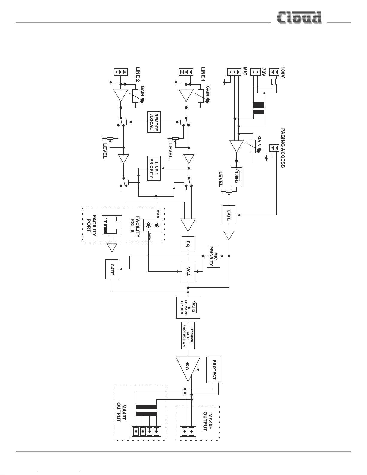
BLOCK DIAGRAM
MA40F/MA40T Installation and User Guide v1.0
14
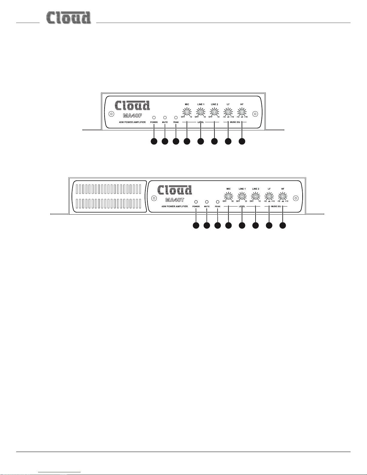
FRONT PANEL DESCRIPTION
16 7 8 2 3 4 5
16 7 8 2 3 4 5
LEVEL controls:
1. MIC – sets volume of signal at the PAGE/MIC input
2. LINE 1 – sets volume of signal at the LINE 1 input
3. LINE 2 – sets volume of signal at the LINE 2 input
EQ controls:
4. LF – LF EQ adjustment of music channel: +/-10 dB @ 100 Hz
5. HF – HF EQ adjustment of music channel: +/-10 dB @ 5 kHz
6. POWER – bi-colour LED: illuminates green when the amplier is active and
red when the amplier is in Automatic Power Down mode
7. MUTE – red LED: illuminates when the MUSIC MUTE function is active
8. PEAK – red LED: illuminates if the amplier’s dynamic clip protection becomes
active
 Loading...