

Page 1
Installation Manual
www.cotytech.com
888-891-9321
ITEM #:MW-M23P
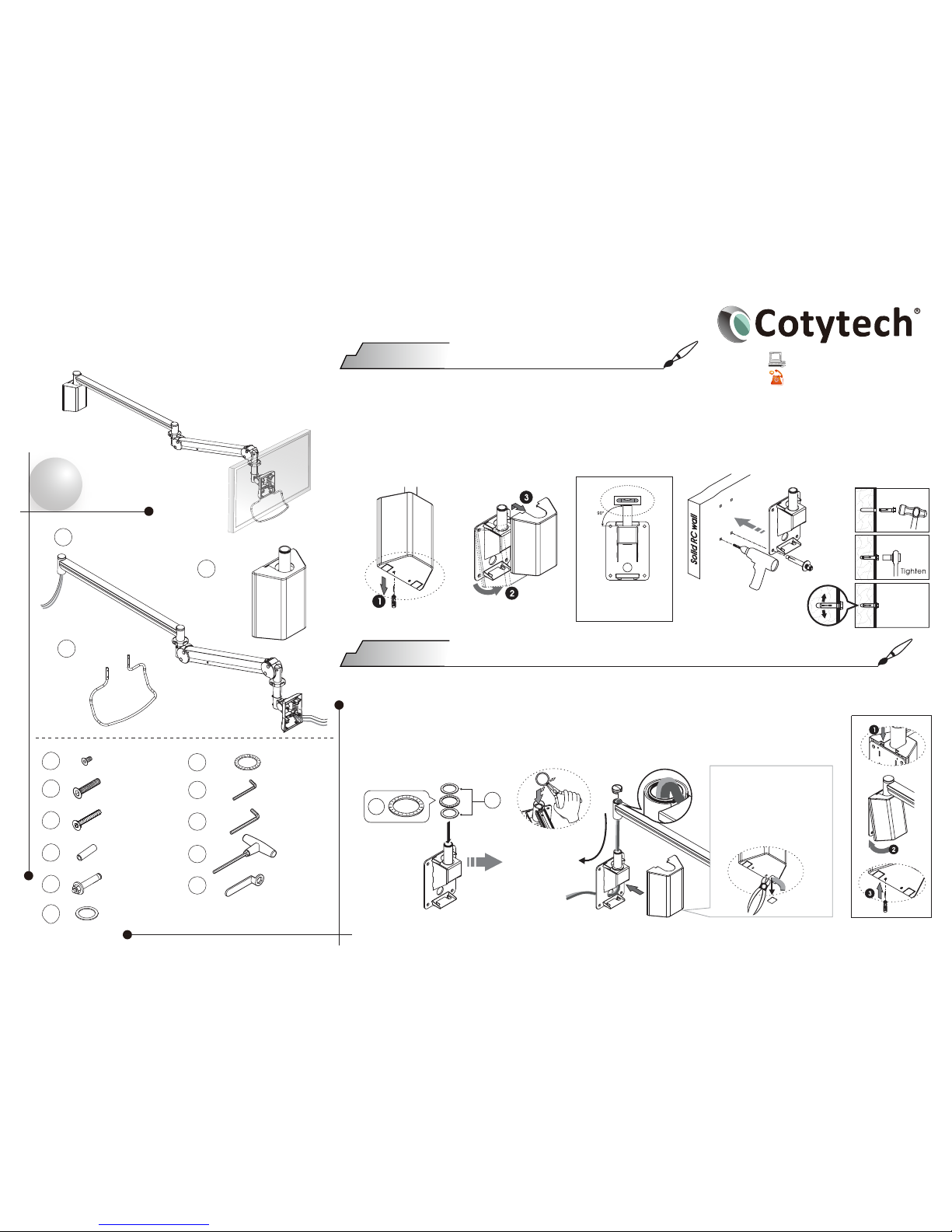
Check
list
X1
X1
01
X1
02
03
X2
09
X1
10
X4
(M4X12)
04
X1
(2.5mm)
11
X4
(M6X40)
05
X1
(4mm)
12
X4
(M4X35)
06
X1
13
X4
07
X4
08
X1
(13”)
14
Use level gauge to
help the wall mount
installation.
Step 1
1.Make sure the substantial wall before assembling.
2.Please take screwdriver to loosen the wall hanger then take out the cover of wall hanger.
Do not discard the cover of wall hanger after take it out!
3.Put the wall hanger on the exact place & height that you want and have 4 marks on the wall.
4.Install the wall hanger on the wall with 4 expansion bolts.
1.Place the bearings onto the spindle.
2.Place the arm onto the spindle and put the end cap on it.
3.Make sure C clip is fitted into groove of spindle securely for collecting
the cables.
4.Fix the cover on the wall mount and screw the cover.
Wall Hanger Assemble
*cables
arrange
Cut off the flake on the
bottom of the cover with
the side-cutting pliers
(not provided) to make a
breach as figure for the
cables to go through (if
necessary).
09
10
Step 2
Only keep the drawing on the assembly guide
1-3
Page 2
Step 3
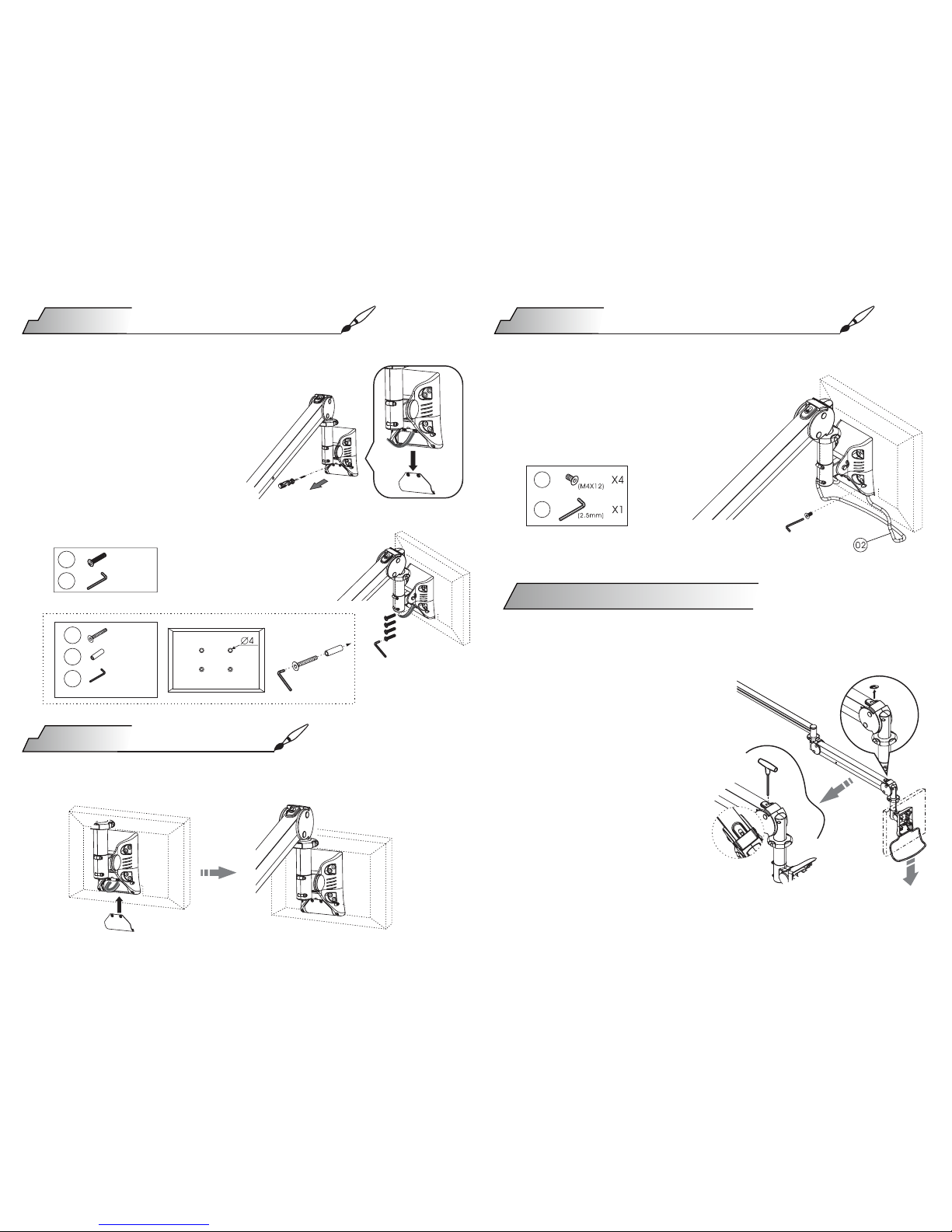
Please remove the back cap by
the screw driver (not provided)
as shown in figure. Please keep
the screws in order to screw back
after the monitor installation are
completed.Then pull out the cable
in order to install the monitor.
Caution for weight capacity adjustment:
Adjustment:
1.Make sure you have
checked out the weight of
the panel you wish to mount.
2.Support the arm throughout/during
assembly.
3.Pull down the arm and take
out the upper cap(See as
below figure)when adjust.
Use the Allen key provided to
adjust the weight capacity.Twist
the Allen key in a clockwise direction
for more weight;counterclockwise
direction for less weight.
1.Please insert the grab handle into the 2
holes on the bottom of universal joint.
2.Then fix the grab handle with 4 screws
by 2.5 mm Allen Key to the 4 holes on
the lower part of universal joint.
Fix the Monitor on the VESA mount using Allen Key and screws.
Please insert the cable to the monitor,complete the circuit and then fix
the cap.
LCD Monitor Assemble
Step 5
LCD Monitor grab handle
Adjustment For Loading
Step 4
Cables Arrange
05 X1
X1
12
(M6X40)
(4mm)
06
X4
X4
07
11
(M4X35)
(4mm)
X1
(2.5mm)
04
11
2-3
Page 3
When assembling the arm with monitors of different
weights.
Caution:
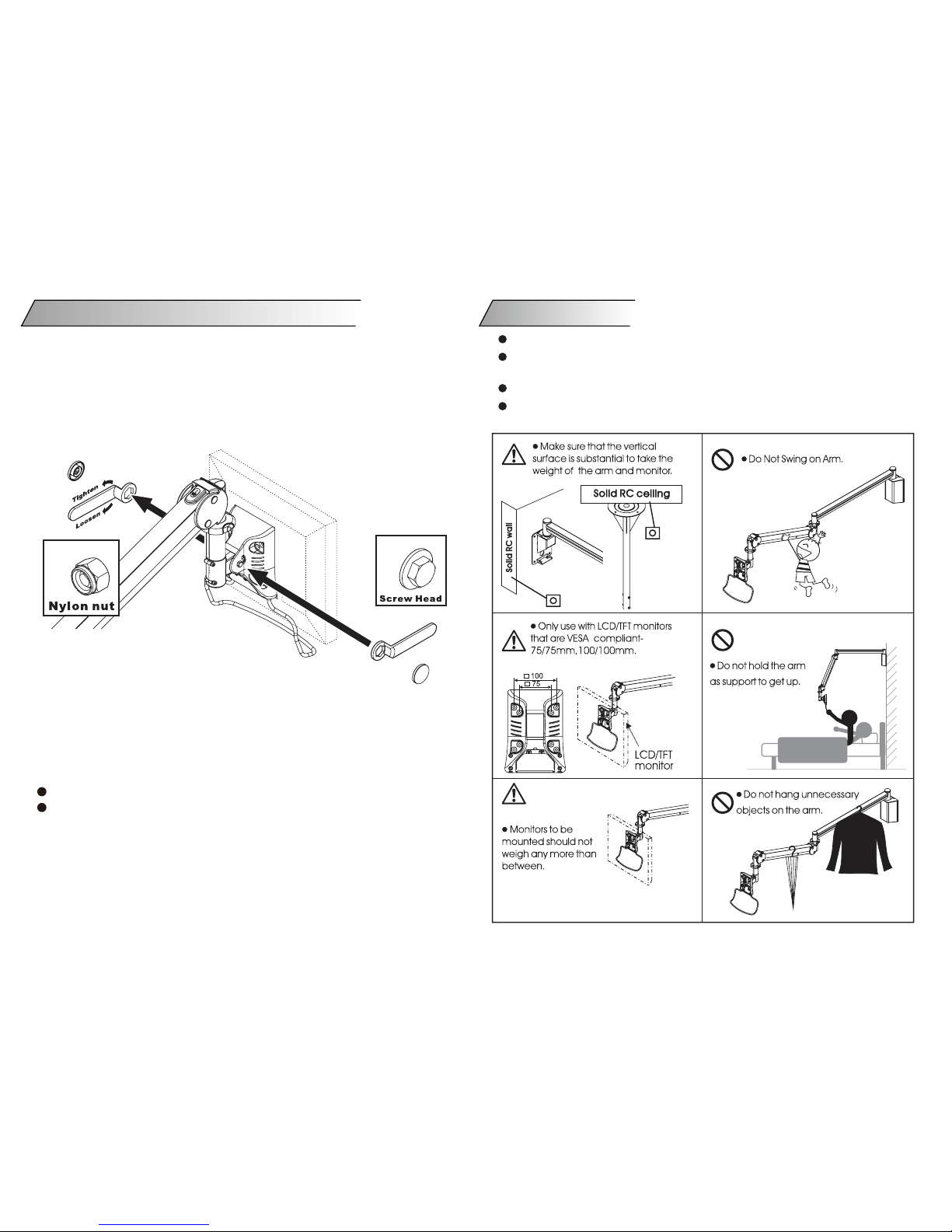
You may find that the tension of the universal joint needs to be
adjusted to ease movement or to maintain the desired monitor
position,If so, adjust as follows:
a.Remove the plastic universal joint cover.
b.Find the nylon nut (not the screw head) and use the provided
wrench to adjust the tension.Fix the screw head by wrench at
the same time when adjust.
c.Use one hand to support the monitor and adjust the tension of the
universal joint.
Clockwise :more tension
Counterclockwise :less tension
d.When the desired tension is achieved,replace the plastic cover.
Support the monitor during the adjustment procedure.
Only adjust the nylon nut (not the screw head).
Do not disassemble the universal joint.
Adjusting Universal Joint Tension
Once assembled DO NOT dis-assemble.
Make sure that mounting screws are suitable for the vertical surface
and adequate to hold the weight of the arm and the monitor.
Support the monitor and arm throughout assembly and mounting.
Keep small parts out of the reach of children.
Safety Notes
3-3
 Loading...