

Page 1
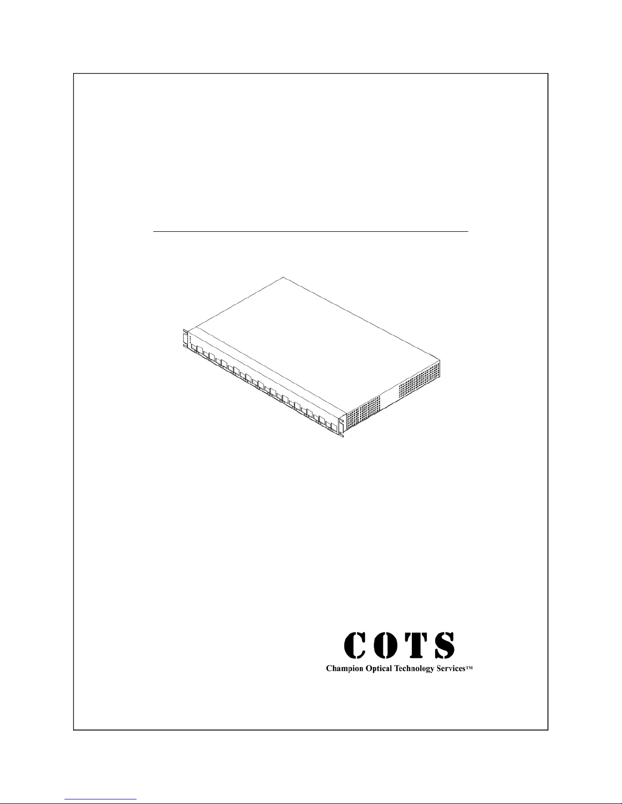
USER GUIDE
CCT100x24-CDM-1213SFx-1255SFx
10/100BaseT To Single Fiber 10/100BaseX
Ethernet Media Converter With
Communications Diagnostics Module
Page 2

Notice
© Copyright Champion Optical Technology Services 2006. All rights reserved.
Reproduction, adaptation, or translation of this manual is prohibited without prior written
permission of Champion Optical Technology Services, except as allowed under copyright
laws.
CCT100x24: Optical To Copper Ethernet Installation Guide
First Edition (January 2006)
Edition 1.5
i
Page 3

Handling Information
Caution
CCT100x24 uses Class 1 laser devices. You should never stare
directly at these devices when they are inserted in the
CCT100x module and it is powered on.
Always use a grounded outlet when powering CCT100x24.
Warning
Before you work on any equipment be aware of the hazards
involved with electrical circuitry. You should be familiar with
standard practices for preventing accidents. Disposal of this
product should be handled according to national and local laws
and regulations.
Storage
This device should be stored in a –4 to 149º F (-20 to 65º C)
environment observing proper electrostatic precautions.
ii
Page 4

Terms & Conditions
Warranty
Effective January 1, 2006:
Champion Optical Technology Services ("COTS") warrants this product from the date of
purchase to the original purchaser for 5 years. The component thereof, but excluding any
software incorporated therein (referred to collectively as the "products" or "equipment") will
be free from defects in material and workmanship. THIS WARRANTY IS IN LIEU OF ALL
OTHER WARRANTIES, EXPRESSED OR IMPLIED, AND CONSTITUTE THE PURCHASER'S SOLE AND EXCLUSIVE REMEDY WITH RESPECT TO THE EQUIPMENT.
In the event that COTS receives returned equipment with defects in material or workmanship,
it will, at its option, repair or replace the equipment to whatever extent it deems necessary to
restore the equipment to proper operating condition. All material and labor required for such a
restoration will be provided at no charge when equipment with material or workmanship defects is properly returned postage or freight prepaid under the procedure described herein
within their applicable warranty period starting from date of purchase. DATED PROOF OF
PURCHASE OR COTS RMA NUMBER MUST BE PROVI DED WITH THE RETURNED
EQUIPMENT.
Limitations
Not covered under the warranties are: failures due to accident, misuse, abuse, neglect, improper installation, product modification, or unauthorized repair or attempted repair, or shipping damage. COTS HEREBY DISCLAIMS ANY AND ALL EXPRESSED OR IMPLIED
WARRANTIES OF MERCHANTABILITY AND FITNESS FOR A PARTICULAR PURCHASE HOWEVER ARISING. IN NO EVENT SHALL COTS BE LIABLE FOR ANY
INCIDENTAL, CONSEQUENTIAL OR SPECIAL DAMAGES OR FOR COMMERCIAL
LOSSES FROM ANY CAUSE INCLUDING, BUT NOT LIMITED TO, LOST PROFITS
OR REVENUES, REGARDLESS OF NOTICE.
THE PRODUCTS ARE NOT AUTHORIZED FOR US E AS CR ITICAL COMPONENTS IN
LIFE SUPPORT DEVICES OR SYSTEMS OR FOR USE IN OTHER CRITICAL APP LICATIONS WITHOUT THE EXPRESS WRITTEN APPROVAL OF THE PRESIDENT OF
COTS . LIFE SUPPORT DEVICES OR SYSTEMS ARE THO SE WH IC H ARE INT ENDED
TO SUPPORT OR SUSTAIN LIFE AND WHOSE FAILURE TO PERFORM CAN REASONABLY BE EXPECTED TO RESULT IN A SIGNIFICANT INJURY TO OR DEA TH
OF THE USER. CRITICAL COMPONENTS ARE THOSE COMP ONENTS WHOSE FAIL URE TO PERFORM CAN REASONABLY BE EXPECTED TO CAUSE FAILURE OF A
LIFE SUPPORT DEVICE OR SYSTEM OR AFFECT I TS SAFETY OR EFFEC TIVENE SS.
CRITICAL APPLLICATIONS ARE THOSE APPLICATIONS THAT MAY INVOLVE
POTENTIAL RISK OF DEATH, PERSONAL INJURY OR SEVERE PROPERT Y OR ENVIRONMENTAL DAMAGE.
iii
Page 5

Terms & Conditions (Continued)
Except as set forth herein, COTS makes no warranties, expressed or implied, and COTS disclaims and negates all other warranties including without limitation, implied warranties of
merchantability, fitness for a particular purpose and conformity to models or samples. In no
event shall COTS be liable for any indirect, special, incidental, or consequential damages.
Customer expressly understands and agrees that COTS does not warrant that the product is
free of claims of patent infringement by any third party. COTS hereby disclaims any such
warranty or indemnification against patent infringement.
Return Procedures
No product may be returned for any reason without the prior approval of COTS. Customer is
responsible for returning products to COTS at customer's risk and expense. Prior to returning
product(s) to COTS for warranty service, customer must obtain a Return Material Authorization (RMA) number from COTS by calling customer service at 440-446-8800. If COTS elects
to replace such part pursuant to the applicable Warranty (see above), replacement parts will be
shipped at COTS’ expense, subject to availability, via a common air delivery service after the
RMA number is obtained. Replacement parts may be refurbished or repaired. COTS shall not
be responsible for failure of the delivery service to make on-time delivery. Customer must
ship the product(s) to COTS in the original packaging, prepaid and insured, with the RMA
number clearly identified on the packaging. Returned products should be shipped to the following address: COTS, Attn: RMA Dept.-RMA No. ___________, 749 Miner Road, Highland Heights, OH 44143. Any product(s) returned to COTS shall become the property of
COTS. If COTS determines that failure of the product(s) was not a result of a defect in materials or workmanship, COTS reserves the right to charge customer for parts and labor at COTS'
then current labor rate. COTS will advise customer prior to assessing these charges. Except as
explicitly provided herein, customer is not authorized to return product to COTS. If COTS
elects to accept unauthorized returns, COTS may, in its sole discretion, charge a restocking fee
for parts returned.
iv
Page 6
Table of Contents
Installation Specifications 1
Description 2
Installation Notes 3
Initial Power Up 4
Connecting Fiber Optic Cables 5
Connecting Ethernet Cables 6
Link Established 7
Link Established Part II 8
Redundant Power 9
Rack Mount Installation
10
CDM Software Quick Set-Up 11
CLI Command Reference 12
CCT100x CDM Web Software 13-18
Troubleshooting 19-20
Troubleshooting Using LEDs 21
Obtaining Technical Assistance 22
Regulatory Approval 22
v
Page 7
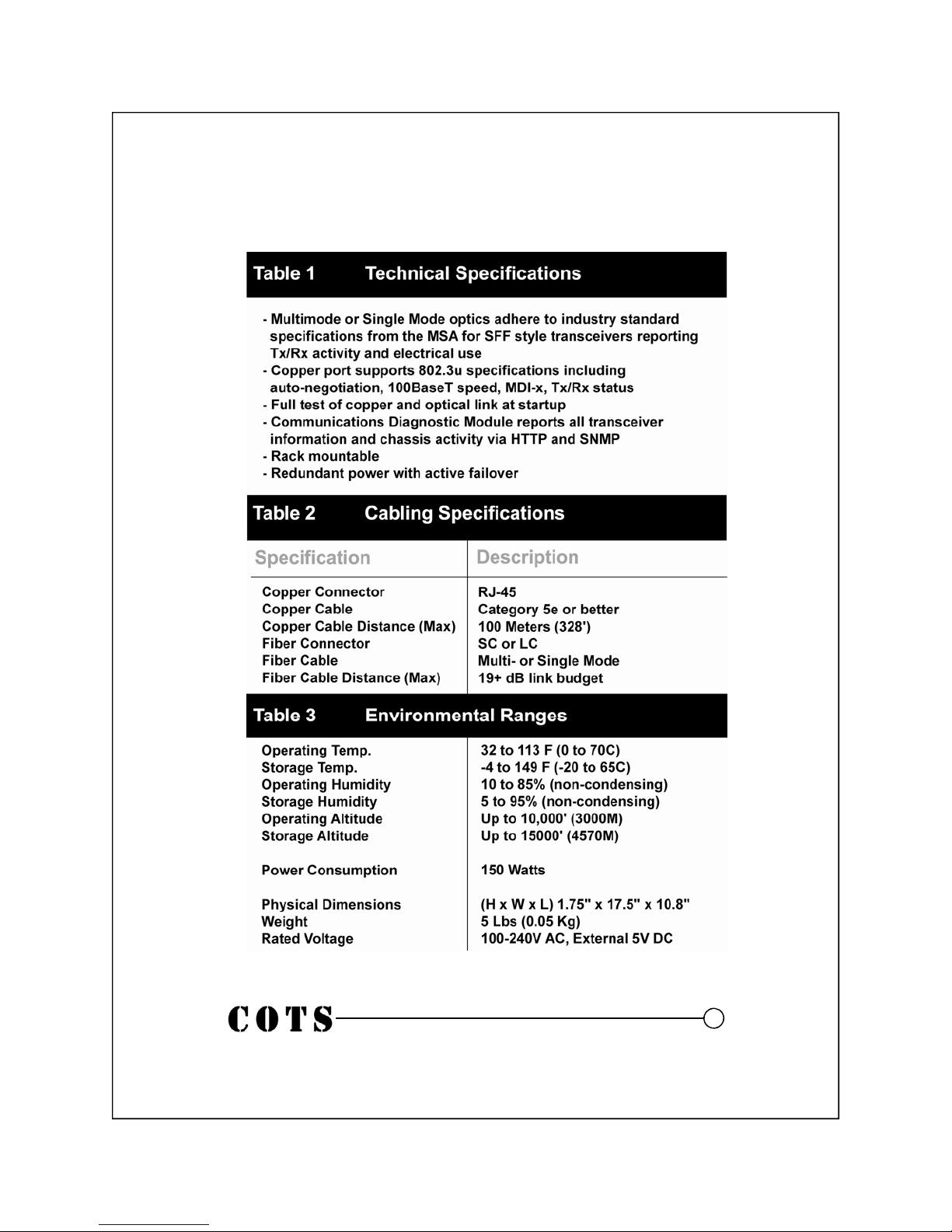
Installation Specifications
1
Page 8

Description
CCT100x24-CDM-1213SFx-1255SFx is a media converter designed to convert optical to copper media running 100Base Ethernet.
There are twelve 1310Tx single fiber transceiver ports with printing
in yellow on the front plate and twelve 1550Tx single fiber transceiver ports with printing in purple on the front plate. CCT100x24
accommodates any of COTS’ 100Base optical transceivers. Use
CCT100x24 for network debug or network management and transport.
The optical to copper connection is wired in silicon and is totally
transparent to the devices it is connected to. Network managers can
set the copper port parameters and know that it will be passed on to
the optical link because CCT100x24 will not link if either of the
connections are down.
With the Communications Diagnostic Module (CDM), status and
performance of the CCT100x24 system and each optical to copper
link is reported, logged, and managed. The CDM controls the 3rd
LED light beneath the Ports and an optional 3 LEDs on the left side
of CCT100x24 under the Power LED.
An optional redundant power supply is available via an external
power adapter.
CCT100x24 is a 24 converter configuration designed to be rack
mounted. A 4-port version is available in a appliance or rack
mounted version.
2
Page 9

Installation Notes
Identifying parts of the CCT100x4 with CDM:
1. Power LED
2. Redundant Power Supply (RPS) Light
3. CDM Tx Light
4. CDM Alarm Light
5. Port 1, Optical wired directly to Copper (SFF)
6. Port 1, Copper wired directly to Optical (RJ45)
7. GO (Link Light) indicating copper & optical links are operating.
8. Tx/Rx Light
9. Port Alarm
10. Ports 1-4 as example, a PORT is both optical and copper
11. CDM Network Port
12. CDM Console Port
13. Redundant Power
14. Fan #1
15. Fan #2
16. Main Power
Figure 1
Front View of CCT100x24
Figure 2
Rear View of CCT100x24
3
Page 10
Initial Power Up
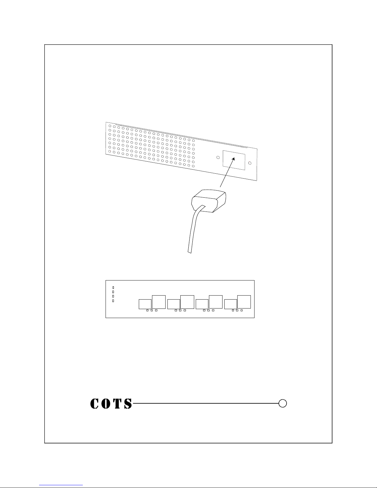
Back Panel
Figure 3
Figure 4
Front View
1. Plug a grounded power cord into CCT100x24.
2. Upon power up, the power LED will illuminate.
3. Each LED will blink as the CCT100x24 goes through diagnostics.
4
Page 11
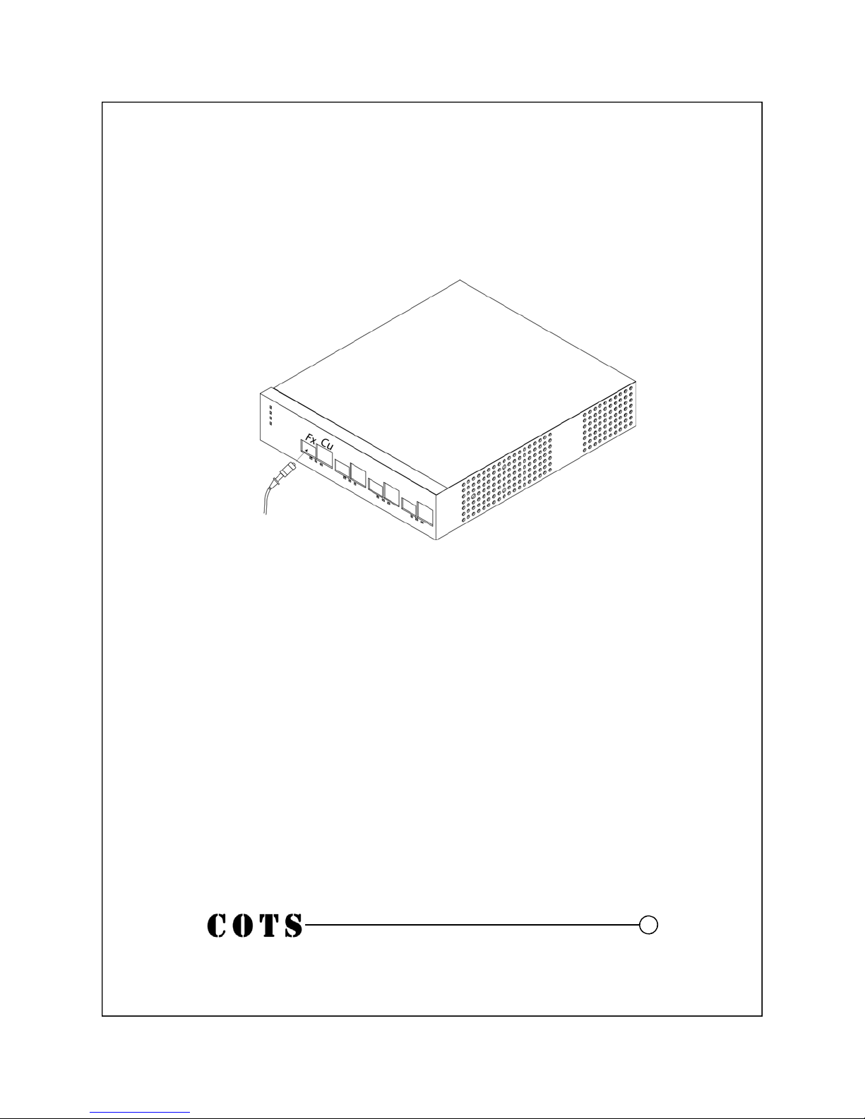
Connecting Fiber Optic Cables
Figure 5
Front Panel
1. Insert the connector of th e fiber optic cable into the receptacle of the
transceiver in CCT100x24-CDM. This type of transceiver is a soldered
down module called an SFF. The mechanical characteristics of this
module are converted by a Multi-Source Agreement. A copy of this
agreement can be found on the Internet or from COTS.
2. The connector, SC or LC, should snap into place. This connector is
plastic and not spring loaded; be careful to insert the connector with a
steady even force. DO NOT PULL THE CABLE WITHOUT RELEASING THE CONNECTOR.
3. Be sure to handle the fiber optic cables carefully. Typically, there
should be no more than a 1.5” bend radius in the cable segment.
5
Page 12
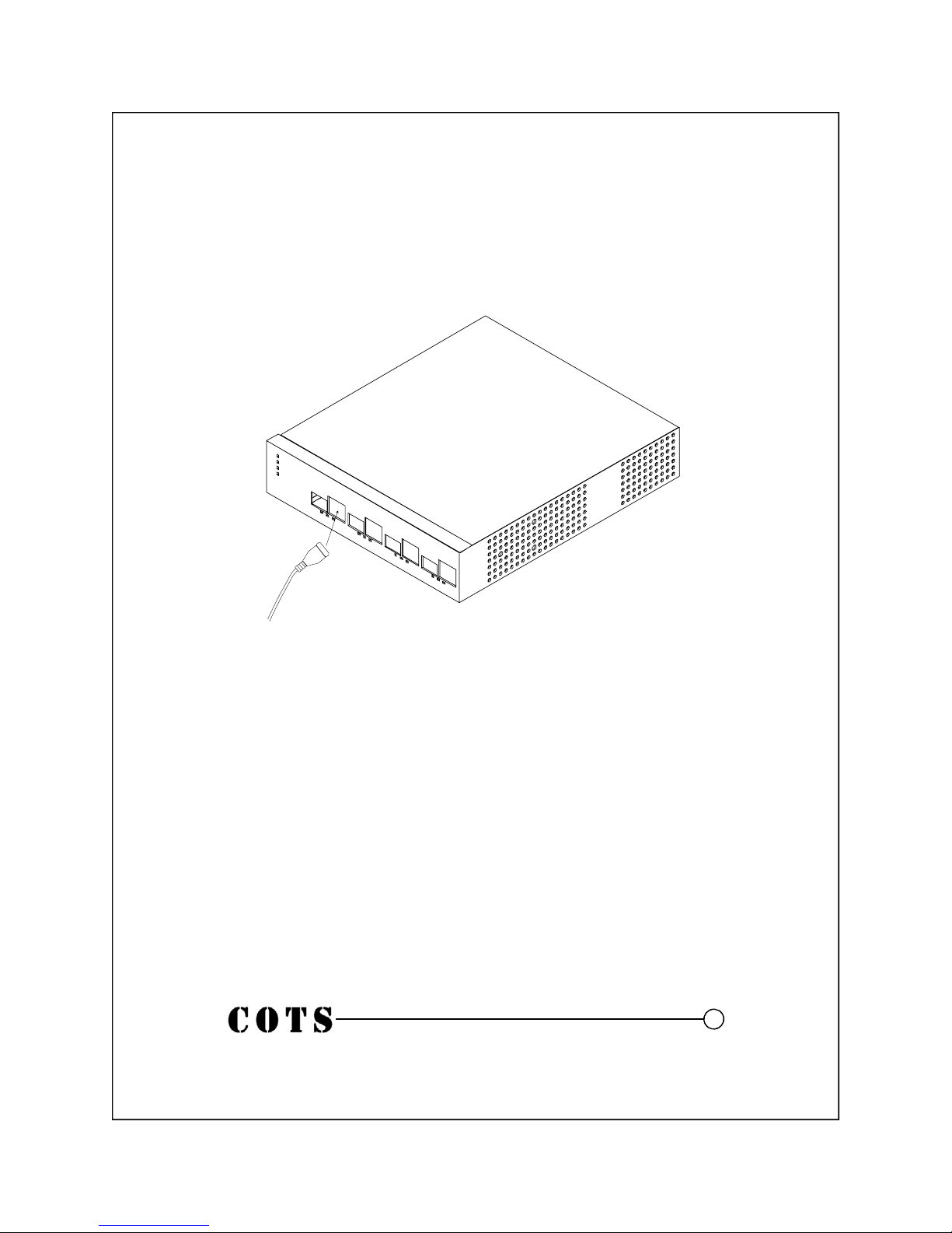
Connecting Ethernet Cables
Figure 6
1. The copper cable should be inserted into the RJ-45 port making sure
the plastic tab snaps into place.
2. Use only Cat5e or higher cabling.
3. Observe industry standards for cable bend radius precautions.
6
Page 13
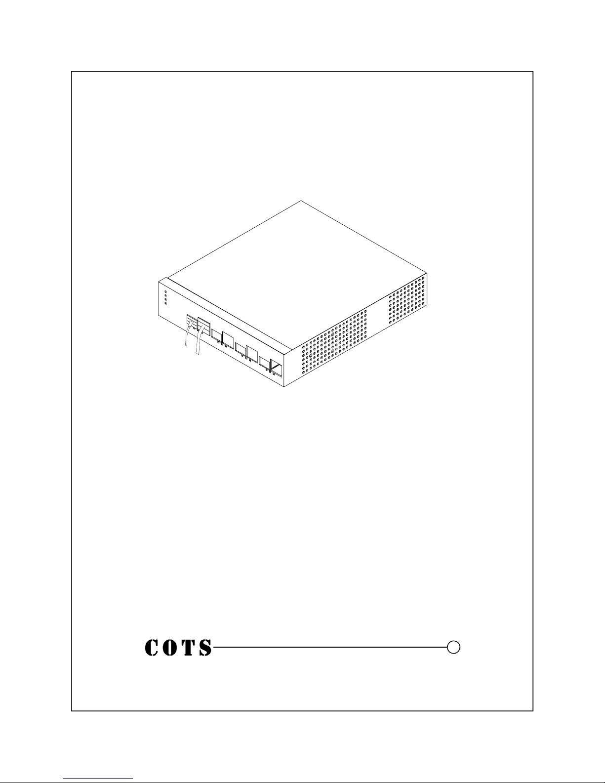
Link Established
Figure 7
1. When both cables are plugged in, a link light will be established on the
devices that each cable is plugged into.
2. Tx/Rx activity will be shown on the middle LED under each Port.
NOTE: A Port is defined as an optical and copper connection, they are wired
together. You can not use the optical connection on Port 1 with the copper
connection on Port 2.
7
Page 14
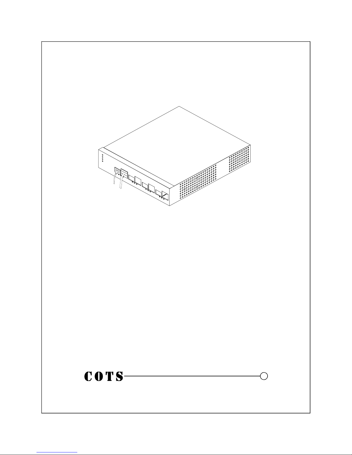
Link Established Part II
Figure 8
Using the diagnostic software, the link setup can be established to allow
the optical link to stay active even if the copper port is disconnected. This
can be helpful when using the CCT100x24 as a media converter to a
packet analyzer.
8
Page 15
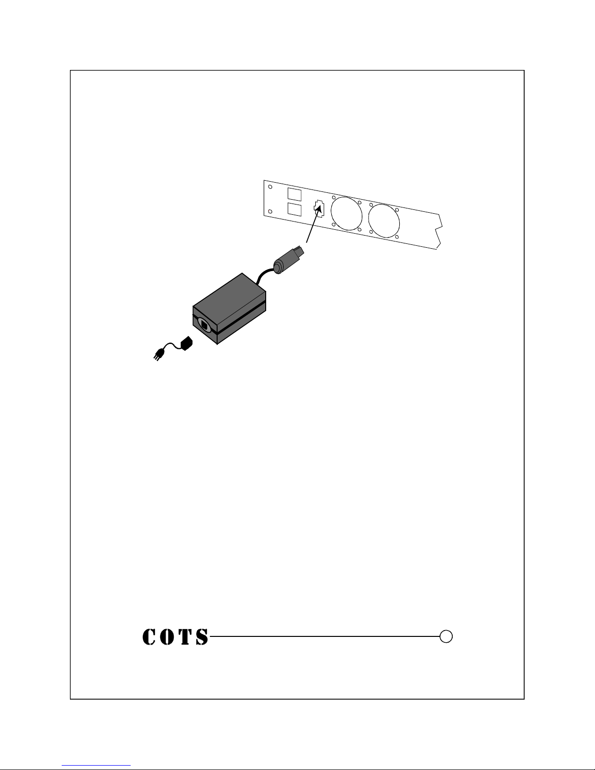
Redundant Power
Figure 9
Redundant Power Supply
1. Plug the power cord into power supply.
2. Plug the redundant power supply into the CCT100x24.
3. Plug the redundant power supply into an AC outlet. It is a hot swappable supply and system; as long as one unit is connected, the
CCT100x24 will remain powered. The diagnostics log tracks power
connectivity.
4. The redundant power LED on the front lights up when the power
adapter is plugged in.
9
Page 16
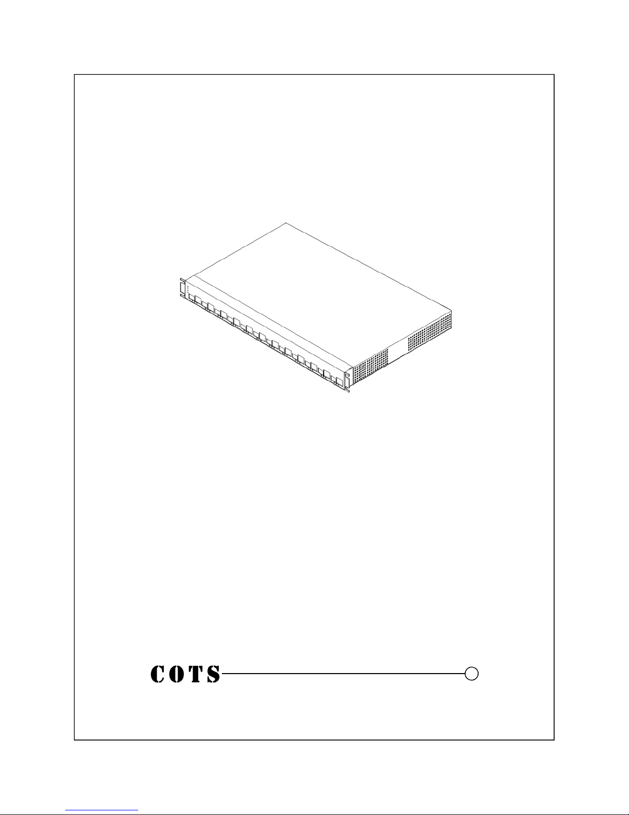
Rack Mount Installation
Figure 10
CCT100x24 includes rack brackets for simple and quick
installation
10
Page 17

CDM Software Setup
1. Connect console cable. The RJ-45 connector plugs into the
black RJ-45 console port on the front of the CCT100x4.
2. Connect to the console port using the included RJ45 serial
cable and open a connection with a program such as HyperTerminal. The port settings should be:
A. Bits per second = 9600
B. Data bits = 8
C. Parity = None
D. Stop bits = 1
E. Flow control = Hardware
3. Press enter. If the connection is successful, you will be at a
prompt (>).
4. Setup the network settings for your network.
To set up a static IP address type:
A. net ipaddr ip_address
B. net mask subnet_mask
C. net gateway default_gateway
D. save
E. net restart
To use DHCP, type:
A. net dhcp
B. save
C. net restart
5. Your CCT100x24 is now configured for your network. If
you are using DHCP, type “net” to see the configuration
and make note of the IP address. You can now log into the
web console to finish configuring your
CCT100x24.
11
Page 18

CDM CLI Command Reference
Command Description
? Lists the console commands
defaults Sets CCT100x back to defaults
help Lists the console commands
location port_number name Sets port location description
mfg Shows assembly information
net Shows saved network settings
net dhcp Toggles DHCP setting on or off
net gateway default_gateway Sets CCT100x4 default gateway
net ipaddr ip_address Sets CCT100x4 IP address
net mask subnet_mask Sets CCT100x4 subnet mask
net restart Stops and restarts networking
net start Starts the networking
net stop Stops the networking
save Saves the network configuration
snmp Displays SNMP info
snmp on/off Turns SNMP on or off
snmp private Sets the read/write password
snmp public Sets the read-only password
snmp trapdest Sets the SNMP trap destination
programall
Updates CCT100x Controller
firmware
12
Page 19
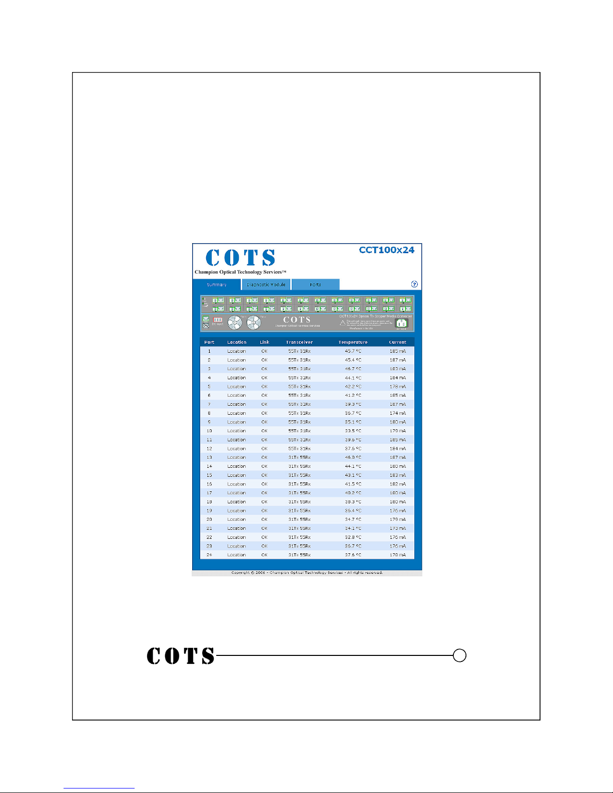
CDM Software Summary Screen
1. Connect the CCT100x4 to your network using the CDM Network port
2. Open a browser and type the IP address of the CCT100x24
3. You will be prompted to log into the unit. The default settings are:
username, admin; password, champion.
4. When you have logged in, you will see the Summary screen:
The green boxes around the port artwork show a live link. The black X
marks show an inactive link. The LED boxes correspond to the status of the
physical LED actions.
13
Page 20
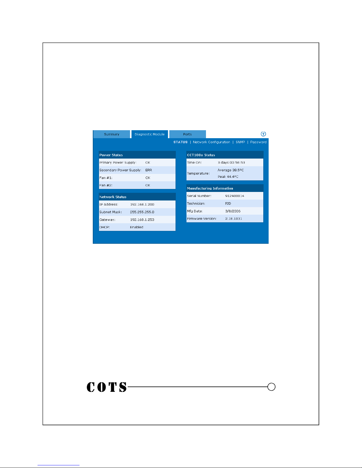
CCT100x24 CDM Diagnostic Module (Cont.)
The Diagnostic Module tab shows information about the CCT100x24 Communications Diagnostic Module (CDM) and basic system information.
• Power Status lists the status of the power supplies and fans, if installed.
• Network Status lists the network configuration.
• CCT100x Status lists the current uptime since the last power-off or reboot
of the system and the peak and average temperatures of the unit.
• Manufacturing Information lists the Serial Number, Technician Initials,
Manufacturing Date, and Firmware Version of the unit.
From the Diagnostic Module screen, you can access the Network Configuration, SNMP, or Password screens, explained on the next page.
14
Page 21
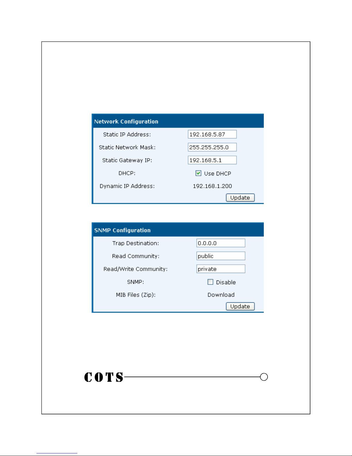
CCT100x24 CDM Diagnostic Module (Cont.)
Go to Network Configuration to change the network settings of the unit.
Note: If you make any changes, you need to log into the web console again.
Go to SNMP to change the SNMP settings of the unit. You can setup the
destination and network parameters for SNMP reporting.
• Trap Destination should be set to the IP address of the host system
• SNMP is enabled by default. To turn SNMP off, check the Disable box
• You can download MIB files in Zip format by clicking “download”
To Change the password, go to the password tab. Note: If you change the
password, you will need to log into the unit again using the new password.
15
Page 22
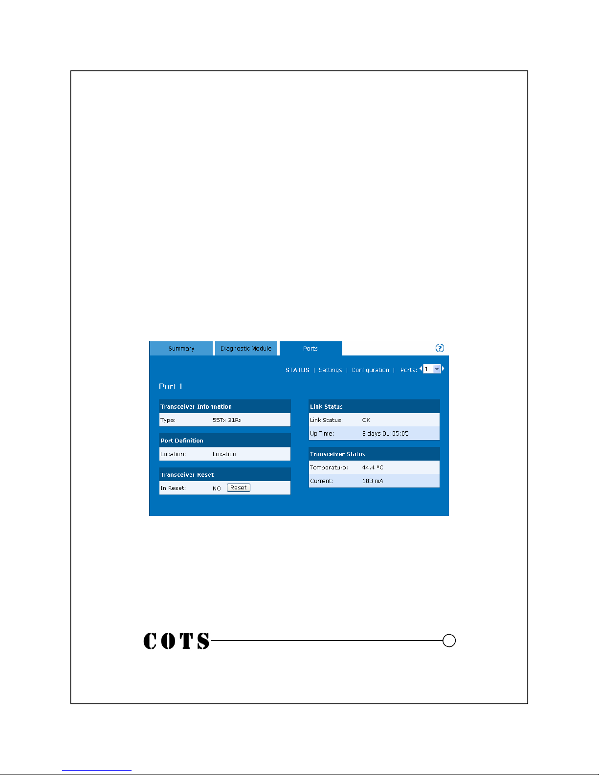
CCT100x24 CDM Web Console Software Cont.
The Ports tab shows information about each port on the CCT100x24. Using
the pull-down menu or arrows, you can switch between the available ports.
• Transceiver Information identifies the transceiver installed at MFR.
• Port Definition displays the name of the port from the Settings tab
• Transceiver Reset forces a restart of the transceiver to clear link problem
• Link Status shows the status and time up of the link
• Transceiver Status shows the ambient temperature near the transceiver.
This number varies. Typical numbers are 30 to 50 degrees C.
• Current shows the electrical draw of the transceiver. This number should
be between 170 and 200 MA. If it varies, check the optical output power
of the transceiver with a power meter.
16
Page 23
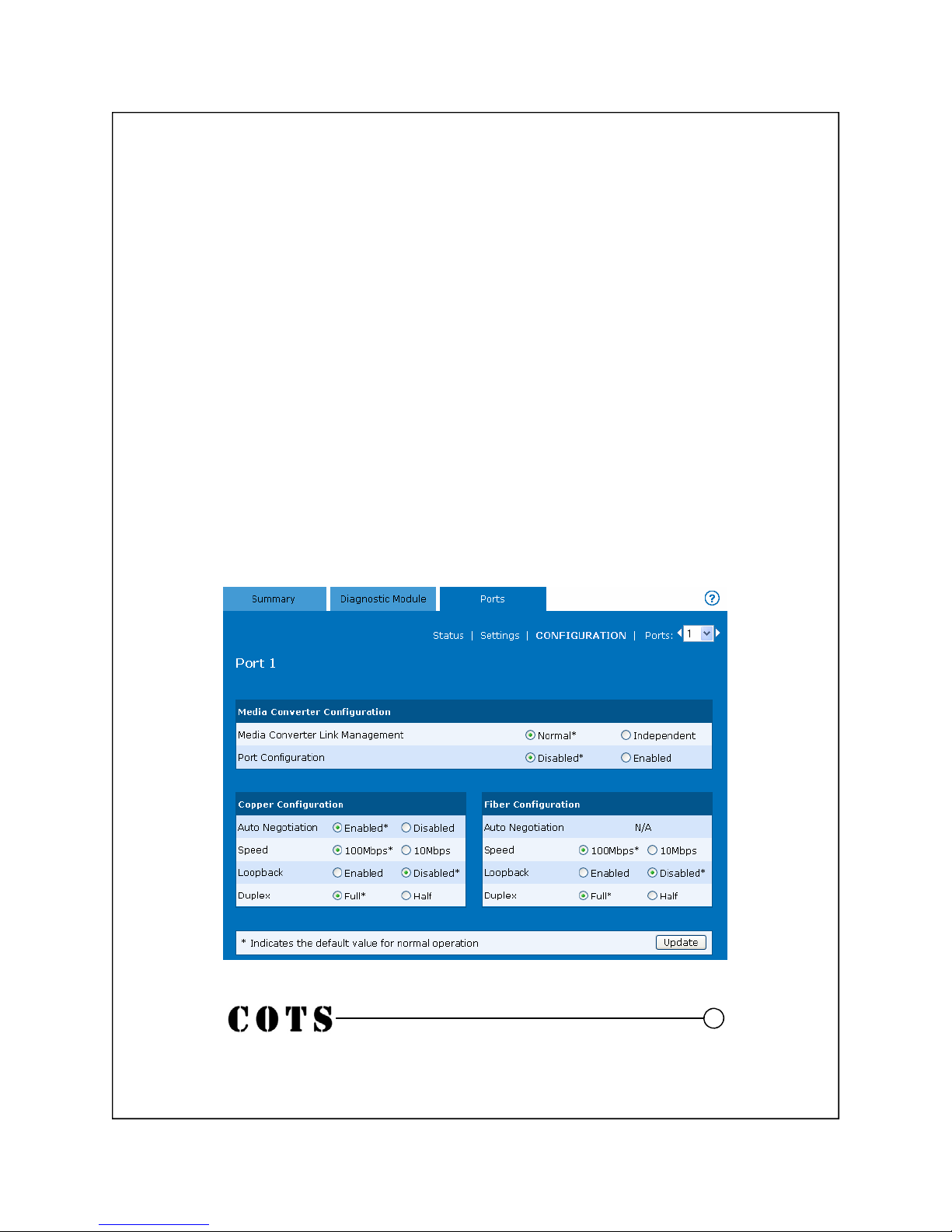
CCT100x24 CDM Diagnostic Module (Cont.)
The Configuration menu under the Ports tab shows information about each port
on the CCT100x24. Using the pull-down menu on the right, you can switch
between the available ports.
CCT100x can be configured to keep an optical link active only if the copper
side is connected as well (Normal) OR set to keep the optical link active on
signal detect only and the copper side acts independently (Independent).
Port Configuration sets the conversion to the default settings. NOTE: When
set to Disabled, none of the bottom settings below can be modified
• Copper Configuration contains all the settings that can be app lied to the
copper connection
• Fiber Configuration contains all the settings that can be applied to the fiber
connection
17
Page 24
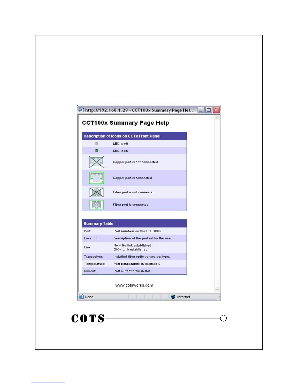
CCT100x24 CDM Diagnostic Module (Cont.)
For more information about the items on any page, click the help icon:
Below is the CCT100x24 Port help window.
18
Page 25

Troubleshooting
How can I use the LED indicators to troubleshoot my connections?
A table is provided on the next page.
Why is the copper port that CCT100x24 is plugged into on my switch resetting?
When a copper port is connected, CCT100x will attempt to initiate a link. The port will turn on
and off at intervals from 4 seconds on/3 seconds off to 20 seconds on/3 seconds off. It will continue to do this until a fiber link is established. If you have a fiber cable installed and the copper
port continues to reset, there may be a problem with the fiber cable.
Can all 10/100/1000 ports in a network switch run at 100Base-T at the same time?
Almost every switch shipped today can run simultaneous 100 Base transport. 100FX is a loose
standard and may require the use of the port reset feature in CCT100x Consult your switch’s technical manual for more information.
Will the copper port on CCT100x4 run at 10BaseT or 100BaseT?
It runs at 10/100BaseT and converts to 10/100BaseX.
Can I run 1000FX transceivers in CCT100x42?
No.
What should the electrical power be and why does it vary for each transceiver?
The electrical current is a real time reading of current draw. The feature allows you to see the
health of the transceivers since the electrical draw is related to the optical output. Consult the
COTS data sheet for exact electrical readout.
Can I troubleshoot my copper and optical links without the other media shutting down when
one side fails?
Yes. The GO Link feature in the software only allows links when both sides are active. This is a
very good indication that data will pass. In the future, you will be able to bring the copper side up
and down without dropping the optical side. You can also force a transceiver to reset which will
reset the PHY in the CCT100x and force a reset along the MAC layer of your network path. This is
a Layer 2 of the OSI model reset.
I have a link light, but no data is passing, why?
The CCT100x24 uses a silicon IC to convert the copper port to the optical port. If the devices
connecting are looking for direct MAC (Media Access Control) connections, the CCT100x24
could initially stop data passing.
When does the CDM Tx light illuminate on the front panel?
The CDM Tx light illuminates when the CDM is transmitting data via the console port or LAN
port. It goes off after a brief period of inactivity.
When does the Error light illuminate on the front panel?
CCT100x does a system check at startup. If a hardware or firmware fault is found it illuminates.
This is a system level error only and has nothing to do with data transmission.
19
Page 26
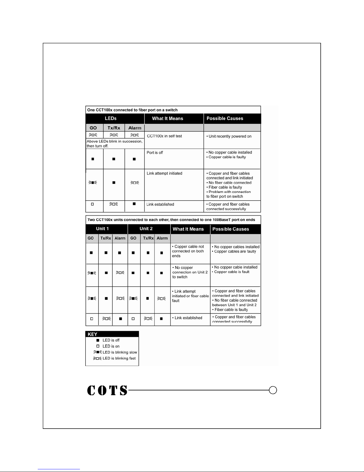
Troubleshooting Using LEDs
20
Page 27
Obtaining Technical Assistance
Contact Tech Support
Phone: 440-446-8800 Fax: 440-815-2204
Hours of Operation
9am-6pm, EST Monday - Friday
Regulatory Approval
THE SPECIFICATIONS AND INFORMATION REGARDING THE PRODUCTS IN THIS
MANUAL ARE SUBJECT TO CHANGE WITHOUT NOTICE. ALL STATEMENTS, INFOR MATION, AND RECOMMENDATIONS IN THIS MANU AL ARE BELIEVED TO BE ACCURATE BUT ARE PRESENTED WITHOUT WAR RANTY OF ANY KIND, EXPRESS OR
IMPLIED. USERS MUST TAKE FULL RESPONSIB ILITY FOR THEIR APPLICATION OF
ANY PRODUCTS.
THE LIMITED WARRANTY FOR THE ACCOMPANYIN G PRODUC T ARE SET F ORTH I N
THE INFORMATION PACKET THAT SHIPPED WITH T HE PRODUCT AND ARE IN CORPORATED HEREIN BY THIS REFERENCE. IF YOU ARE UNABLE TO LOCATE THE
WARRANTY, CONTACT YOUR CHAMPION OPT ICAL TECHNOLOGY SERVICES REPRESENTATIVE FOR A COPY.
Modifications to this product not authorized by COTS could void the Agency approvals and
negate your authority to operate the product.
NOTHWITHSTANDING ANY OTHER WARRANTY HEREIN, ALL DOCUMENT FILES
AND SOFTWARE OF THESE COTS AND THE AB OVE-NAMED SUPPLIERS DISCLAIM
ALL WARRANTIES, EXPRESSED OR IMPLIED , INCLUDING, WITHOUT LIMITATION,
THOSE OF MERCHANTABILITY, FITNESS FOR A PARTICULAR PURPOSE AND NONINFRINGEMENT OR ARISING FROM A COURSE OF DEALING, USAGE, OR TRADE
PRACTICE.
IN NO EVENT SHALL COTS OR ITS SUPPLIERS BE LIABLE FOR ANY INDIR ECT, SPECIAL, CONSEQUENTIAL, OR INCIDENTAL DAMAGES, INCLUDING, WITHOUT LIMITATION, LOST PROFITS OR LOSS OR DAMAGE TO DATA AR ISING OUT OF THE USE
OR INABILITY TO USE THIS MANUAL, EVEN IF COTS OR ITS SUPPLIERS HAVE
BEEN ADVISED OF THE POSSIBILITY OF SUCH DAMAGES
21
Page 28

749 Miner Rd. Highland Heights, OH 44143
www.cotsworks.com
Phone: 440-446-8800
Fax: 440-815-2204
 Loading...