

Page 1

TR-40 User’s Manual
40A Transfer Switch
Page 2

Page 3

Table of Content
1. IMPORTANT SAFETY INFORMATION 1
1-1.General Safety Precautions 1
1-2.Other Safety Notes 1
2. INTRODUCTION 2
2-1. System 2
2-2. Application Block Diagram 2
2-3. Panel introduction and terminal description 2
2-4. LED status 4
2-5. Electrical Specification 4
2-6. Mechanical Drawings 5
2-7. Standard Accessory 6
3. INSTALLATION AND OPERATION 6
4. TROUBLESHOOTING 10
5. WARRANTY 10
Page 4

Page 5

1
1. Important Safety Information
1-1. General Safety Precautions
Warning! Before using the Inverter, read the safety
instructions.
z Do not expose the transfer switch to rain, snow, spray or dust. To
reduce the risk of fire hazard, do not cover or obstruct the
ventilation openings and do not install the inverter in a
zero-clearance compartment.
z To avoid the risk of fire and electric shock, make sure that the
existing wiring is in good electrical condition, and the wire size is
not undersized.
z This equipment contains components which can produce arcs or
sparks. To prevent fire or explosion do not install in compartment
containing batteries or flammable materials or in location which
require ignition protected equipment. This includes any space
containing gasoline-powered machinery, fuel tanks, or joints,
fittings, or other connection between components of the fuel
system.
z The following precautions should be taken when working on the
transfer switch:
Step 1 Remove watches, rings, or other metal objects
Step 2 Use tools with insulated handles
Step 3 Wear rubber gloves and boots
1-2. Other Safety Notes
z Upon receipt, examine the carton box for damage. If you have
found any damage on the carton box please notify the company
you purchased this unit from.
z Do not operate near water or in excessive humidity.
z Install the transfer switch in a well-ventilated area. Do not block
the front air vents, or the rear air exhausts of the unit.
z Do not operate the transfer switch close to combustible gas or
open fire.
Page 6
2
2. Introduction
2-1. System
The unit is a highly reliable transfer switch, designed with advanced
power electronic and microprocessor technology offering the
following features:
Low power consumption <1.3W
Universal AC input, full range
Cooling by free air convection
Switching current up to 40 amps
High transfer speed
Applicable models: SP-700/1000/1500/2000/3000/4000
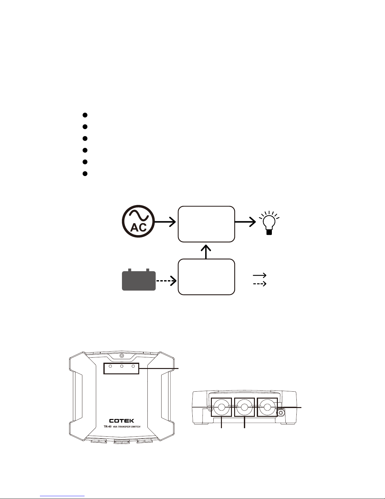
2-2. Application Block Diagram
2-3. Panel introduction and terminal description
2-3-1. Panel introduction
Fig. 2 Panel introduction
Fig. 1 Application block diagram
AC source
Load
AC
DC
TR-40
Transfer Switch
SP series
Inverter
Battery
INV.
INPUTACOUTPUT
GRID
INPUT
Status LED
Grid Input
AC OutputInverter
Input
Page 7
3
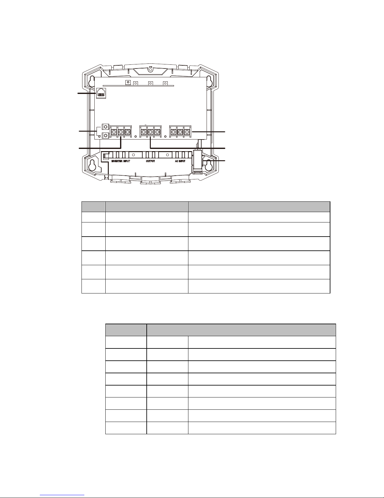
2-3-2.
Terminal description
Fig. 3 Terminal description
Description Function
A TRC Port (RJ-45) SP series inverter communication port
B N terminal N to ground
C Inverter Input terminal Inverter AC power input terminal
D AC Input terminal Grid AC power input terminal
E Output terminal Output power terminal
F Circuit Breaker (40A) Grid power over load protection
Table 1. Panel introduction and terminal description
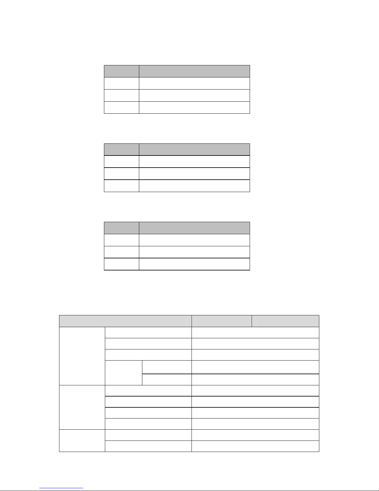
2-3-3. TRC port definition
Pin Num. Definition
1 Reserved --
2 PH-L Zero-crossing signal
3 PH-N Zero-crossing signal
4 Bypass transfer switch driver signal
5 12V Internal power for TR-40 controller
6 5V Internal power for TR-40 controller
7 GND The same polarity and the negative battery
8 Reserved --
Table 2. TRC port definition
A
B
C E
D
F
Page 8
4
2-4. LED status
2-4-1. INV. INPUT
LED Signal Description
Green Inverter input normal
Red Inverter not synchronous
Off No Inverter input
Table 3. INV. input LED description
2-4-2. AC OUTPUT
LED Signal Description
Green INV provides power to Load
Orange Grid provides power to Load
Off No AC output
Table 4. AC output LED description
2-4-3. GRID INPUT
LED Signal Description
Green Grid input normal
Red Grid not synchronous
Off No Grid input
Table 5. GRID input LED description
2-5. Electrical Specification
Model TR-40A TR-40B
Contact
Rating
Max. switching voltage 277VAC
Max. switching current 40A
Max. switching power 11000VA
Switching
time
INV to GRID 10mS
GRID to INV 60mS
Control
Voltage range 100~240VAC
AC current (Typ.) 21mA / 100VAC, 16mA / 240VAC
Frequency range 47~63Hz
Power consumption <1.4W (at no load)
Protection
Wiring errors LED inform
Grid overload Circuit breaker (40A)
Page 9
5
Model TR-40A TR-40B
Environment
02-.pmet gnikroW
~40
Working humidity 20~85% RH non-condensing
Storage temp., humidity -40 ~85 , 20~85%
Vibration
10~500Hz, 2G 10min / 1 cycle, period for
60 min each along X,Y,Z axes
Safety &
EMC
Safety standards CE, EN60947-1; EN60947-6-1
22055NEIME
Safety &
EMC
Power harmonic & voltage
fluctuation and flicker
EN61000-3-2, EN61000-3-3
Others
EMS immunity EN55024, IEC61000-4-2, 3,4,5,6,8,11
Dimension (WxHxD) 220x71x194 mm / 8.66x2.80x7.64 inch
Table 6.TR-40 Electrical Specification
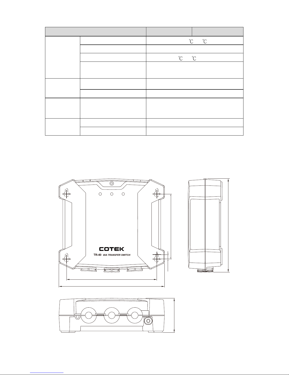
2-6. Mechanical Drawings
Unit: mm [inch]
Fig. 4 Mechanical drawings
INV.
INPUTACOUTPUT
GRID
INPUT
220 [8.66]
194 [7.64]
71 [2.80]
9.3
[0.37]
135.0 [5.31]
188.0 [7.40]
Page 10
6
2-7. Standard Accessory
TRC Cable, 1800mm x 1pcs
Copper for N Terminal x 1pcs
3. Installation and Operation
Note 1: Please make sure the load power consumption is not over
inverter output power.
Note 2: Please make sure the inverter output settings (output
voltage and frequency) should be the same as the Gird
power.
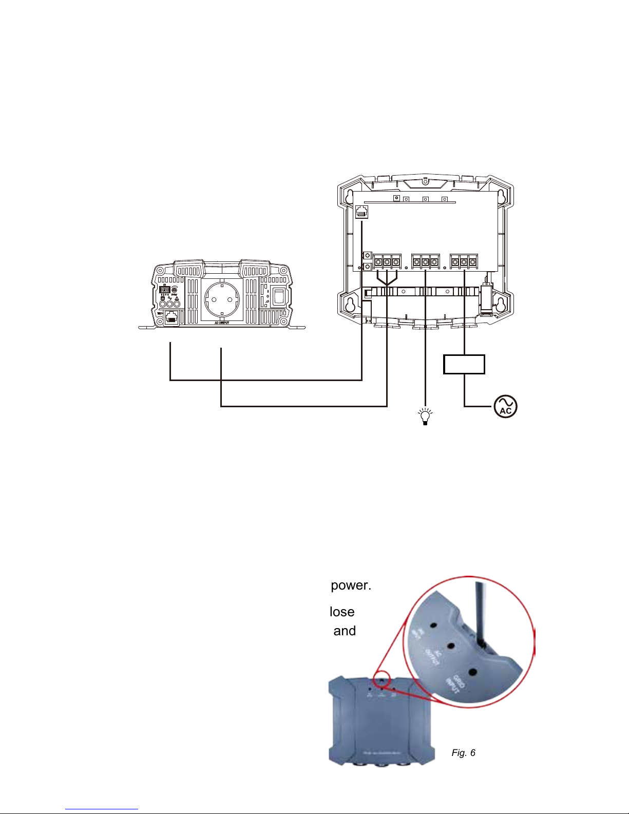
Step 1 Pease follow the installation drawing to connect the TR-40,
inverter, load and Grid power.
remove the cover
A. Use screw driver to lose
the screw on t
he cover and
Fig. 6
Fig. 5 TR-40 wiring diagram
SP Series
TRC AC
Output
INVERTER INPUT OUTPUT AC INPUT
Load
Breaker
Page 11
7
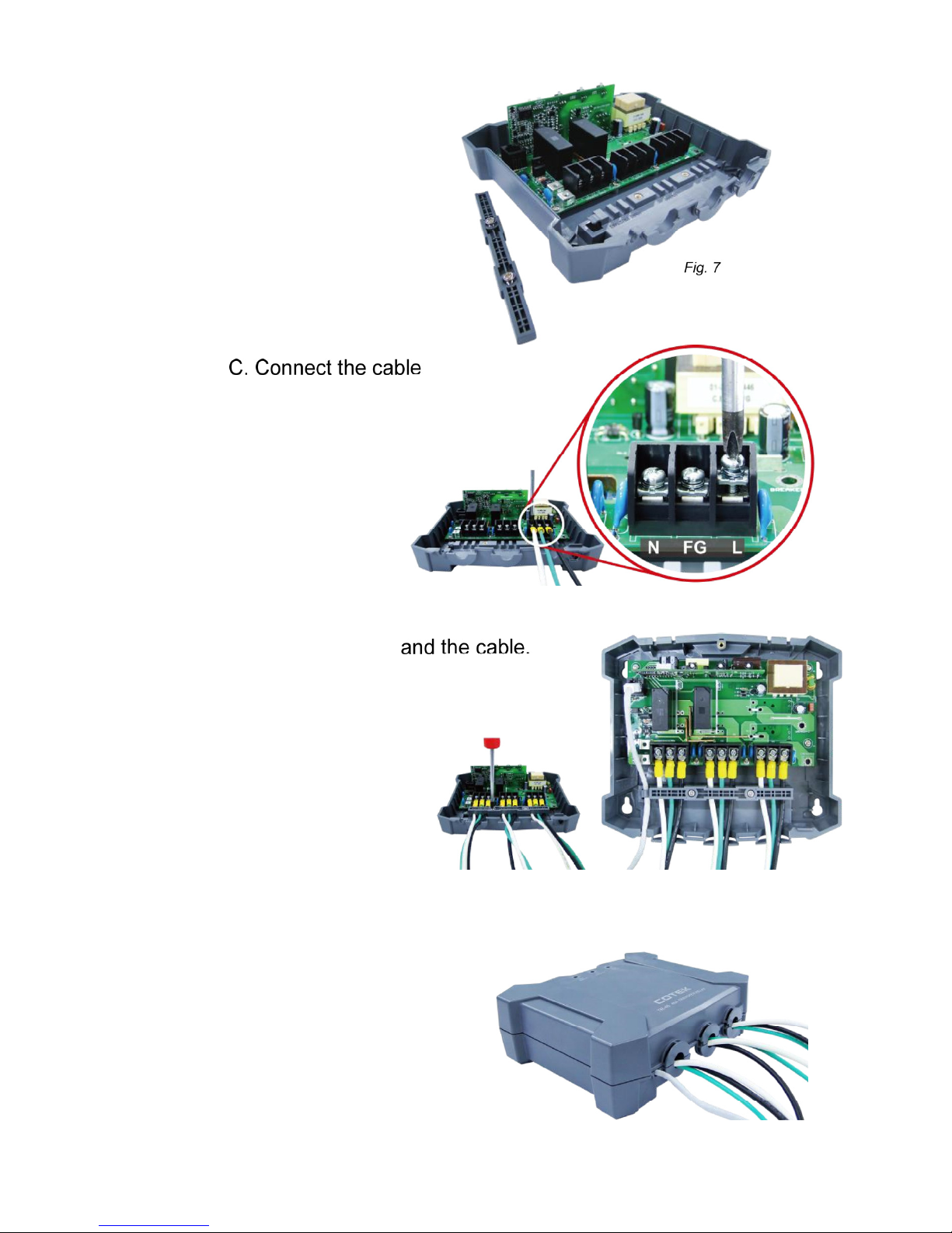
B. Use screw driver to
lose the layering
D. Fix the layering
E. Fix the cover and connect the
cable to inverter, load and
Grid power.
(Please refer to Fig.1
wiring diagram)
Fig. 8
Fig.9
Fig. 10
Page 12
8
Step 3 Turn on the inverter power to make sure the inverter is
working normal and turn off the inverter.
Step 4 Switch on the breaker to provide power to TR-40.
Step 5 Turn on the inverter. When power on the inverter, it will
take 15 seconds for frequency and phase locking. After
frequency and phase is locked, the internal relay will
switch to “Grid input”. The LED of “AC OUTPUT” will turn
orange. Grid AC provides the energy to the load. The
system works normal.
Note! In case of AC OUTPUT do not switch, please follow
the troubleshooting guide.
Warning!
1. Before the wiring connection, it’s important to make sure
there is no power feed in and inverter must be switched off.
2. Wire diameter: user need to use / select the suitable cable
gauge. Please contact the COTEK distributor for installation.
3. TR-40 max. output current is 40A and we considered the
cabling, we need to use 40Ax1.25= 50A to select the cable.
Consider the two important factors for the cable size
determination
z NEC Table 310.15(B)(2)(A) Ambient Temperature
Correction Factors Based on 30°C.
z NEC 310.15(B)(16) Allowable Ampacities of Insulated
Conductors Rated Up to and Including 2000 Volts, 60
Through 90 , Not More Than Three Current-Carrying
Conductors in Raceway, Cable, or Earth(Directly Buried),
Based on Ambient Temperature of 30
.
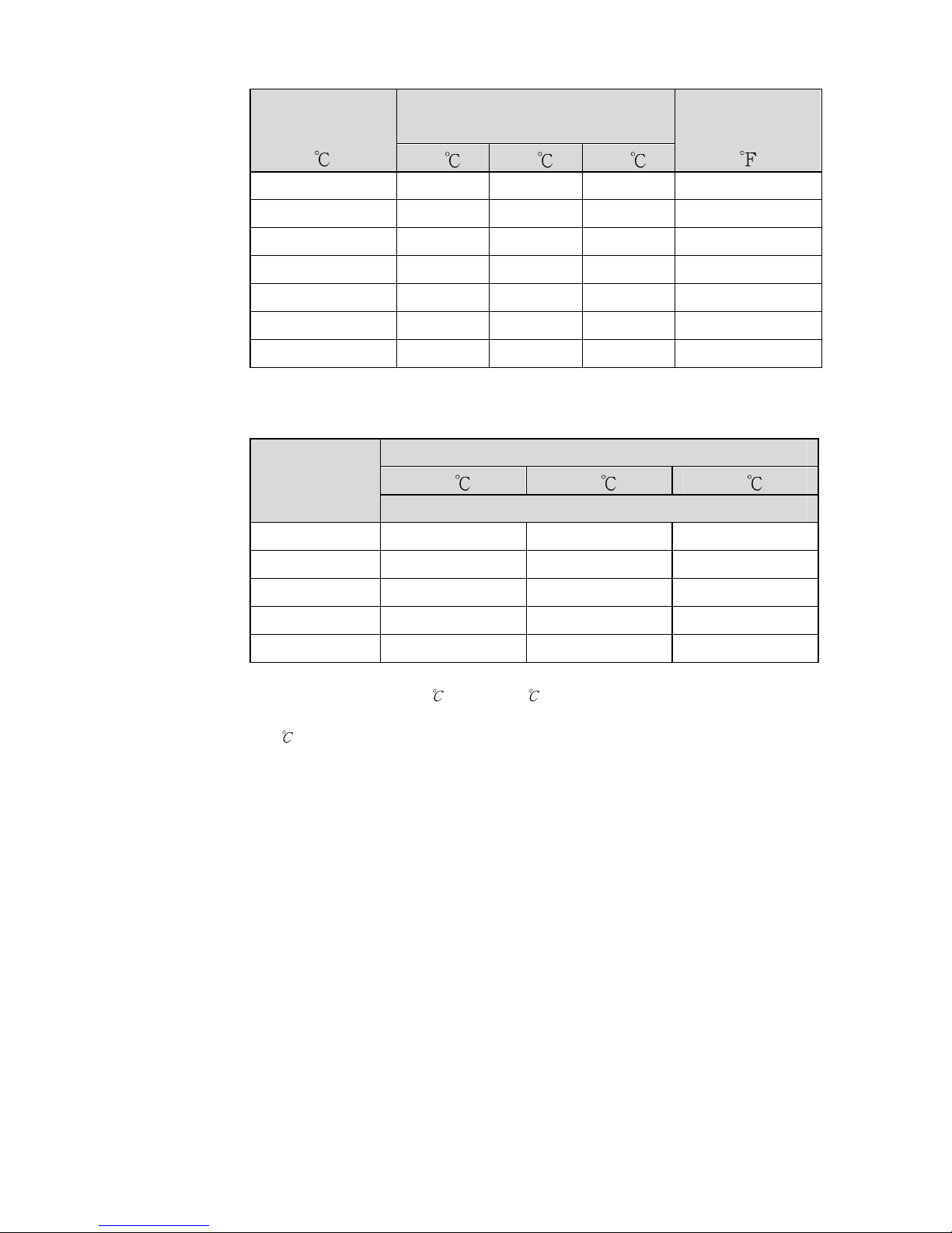
We suggest user select the AWG#6 for TR-40.
In case of the application do not need such high current, user
can determine the cable based on the following table.
Page 13
9
Ambient
Temperature
( )
Temperature Rating of
Conductor
Ambient
Temperature
( )
60 75 90
10 or less 1.29 1.20 1.15 50 or less
11-15 1.22 1.15 1.12 51-59
16-20 1.15 1.11 1.08 60-68
21-25 1.08 1.05 1.04 69-77
26-30 1.00 1.00 1.00 78-86
31-35 0.91 0.94 0.96 87-95
36-40 0.82 0.88 0.91 96-104
Table 7. NEC Table 310.15(B)(2)(A) Ambient Temperature Correction Factors Based on
30°C.
A.W.G
Copper Temperature
60 75 90
Current (A)
14 15 20 25
12 20 25 30
10 30 35 40
840 50 55
655 65 75
Table 8. NEC 310.15(B)(16) Allowable Ampacities of Insulated Conductors Rated Up to
and Including 2000 Volts, 60
Through 90 , Not More Than Three Current-Carrying
Conductors in Raceway, Cable, or Earth(Directly Buried), Based on Ambient Temperature
of 30
.
Page 14
10
4. Troubleshooting
LED Status Signal Description Suggestion actions
Grid Input LED Red
twinkling
Grid not synchronous Please wait and check the Grid input
Grid Input LED Off No Grid input
Please power off the system and make
sure the Grid input cable are connect
correctly
INV input LED Red Inverter not synchronous
Please power off the system and make
sure the Inverter Input cable are connect
correctly
INV input LED Off No Inverter input
Check the inverter status – On / Off
Check the cable between inverter and
TR-40
AC output LED off No AC output
Check the Grid input cable and grid
status
Check the inverter input cable and
inverter status (on / off / alarm)
Table 9.Troubleshootingguide
5. Warranty
We guarantee this product against defects in materials and
workmanship for a period of 24 months from the date of purchase. In
case you need to repair or replace any defective power inverters, please
contact COTEK local distributor.
This warranty will be considered void if the unit has been misused,
altered, or accidentally damaged. COTEK is not liable for anything that
occurs as a result of the user’s fault.
Page 15

Page 16

No.33, Sec. 2, Renhe Rd., Daxi Dist., Taoyuan City 33548, Taiwan
Phone
+886-3-3891999 FAX +886-3-3802333
http
// www.cotek.com.tw
2015.09._A0
 Loading...