

Page 1
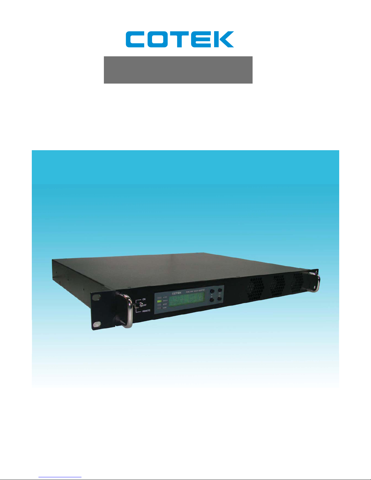
SR Series
1KW Pure Sine Wave Power Inverter
User ’s Manual
Page 2

Page 3

Contents
1
1.
Important Safety Instructions…………………………………………………………………….
3
1-1 General Safety Precautions..………………………………………………………………… 3
1-2 Other Safety Notes..……………………...…………………………………………………… 3
Rack-Mounted Installation…………...………………………………………………….........
2.
Functional Characteristics Introduction ...…………………………………………………….
5
2-1 System...………………………………………………………………………………………..
2-2 Block Diagram.…………………..…………………………………………………………….
2-3 Electrical Performance…..…………………………………………………………………….
2-4 Mechanical Drawings..………………………………………………………………………...
3.
Installation and Maintenance….………………………………………………………………….
9
3-1 Rear Panel…...…..…………………………………………………………………………….
3-2 Front Panel..……..……………………………………………………………………………..
3-3 Maintenance…….………..……….…………………………………………………………....
4.
Operation…………………………………………………………………………………………….
14
4-1 Connecting the Input Power…………………………………………………………………..
4-2 Connecting the Loads..………………………………………………………………………..
4-3 Inverter Operation...………..………………………………………………………………….
4-4 Protection Features…………………………………………………………………………….
5
Front LCD Panel Display and Setup…………………………………………………………….
15
5-1 LCD Panel Indications………….……………………………….…………………………….
5-2 Startup Sequence and Standby Status…..……….……………..…………………………..
5-3 Setup Menu Operation and Instructions……………………………..……………………...
6.
RS232 Communication and Operation…..……………………………………………………..
6-1 Operation of the RS-232 Serial Port..……. ………………………….……………………..
6-2 Interface Commands..……………………………………………..…………………………..
6-3 Example of the RS232 Operation……………………………………………………….……
1-3
4
14
9
14
5
6
7
8
14
15
15
15
15
17
18
23
23
24
24
Page 4

Copyright: This manual is the copyright of COTEK Electronic Industrial. Co., Ltd. And may not be reproduced or copied
without the express permission of the owner.
2
7. Information…………………………………………………………………………………………..
29
7-1 Troubleshooting……………………………………………………………………………….. 29
7-2 Warranty……………………………………………………………………………………...... 29
Page 5
SR Series Inverter
1. Important Safety Instructions
1-1. General Safety Precautions
1-1-1. Do not expose the inverter to rain, snow, spray or dust.
To reduce the risk of fire hazard, do not cover or obstruct the
ventilation openings and. do not install the inverter in a zeroclearance compartment.
1-1-2. To avoid the risk of fire and electric shock, make sure that the
existing wiring is in good electrical condition; and that the wire size
is not undersized.
Do not operate the inverter with damaged or substandard wiring.
1-1-3. Depending on the use, the AC output of the inverter may require
user installed breaker or fusing. For telecom use, a GFCI has not
been provided. The inverter incorporates standard AC short circuit
protection.
1-1-4. The following precautions should be taken when working on the
inverter:
Remove watches, rings, or other metal objects.
Use tools with insulated handles.
Wear rubber gloves and boots.
1-1-5. If one of the following situations arises, get the equipment checked by
service personnel:
a. Liquid has penetrated into the equipment.
b. The equipment has been exposed to moisture.
c. The equipment has not work well or you can not get it work according
to user‘s manual.
d. The equipment has dropped and damaged.
e. If the equipment has obvious sign of breakage.
WARNING!
SAVE THESE INSTRUCTIONS – This manual contains
important instructions that should be followed during
installation and maintenance of the inverter.
1-2. Other Safety Notes
1-2-1. Upon receipt, examine the shipment box for damage. Notify the
carrier immediately, before opening, if damage is evident.
3
Page 6

SR Series Inverter
1-2-7. Install the inverter in a well-ventilated area. Do not block the front
air vents, or the rear air exhausts of the unit.
1-2-8.
proper use; correct wiring sizes must be ensured.
1-2-9. Mount the inverter such that the fan axis is horizontal.
1-2-10.Do not operate the inverter close to combustible gas or open fire.
1-2-11. Do not operate appliances that may feed power back into the
inverter.
1-2-12.Temperature: The inverter should be operated in an ambient
may be affected. Air flow to the inverter must not be restricted.
1-2-2. Do not operate near water or in excessive humidity.
1-2-3. Do not open or disassemble the inverter, warranty may be voided.
1-2-4. The DC side connections should be firm and tight.
1-2-5. Grounding: Reliable grounding of rack-mounted equipment should
be maintained.
1-2-6. Do not drop a metal tool on the battery. The resulting spark or short-
circuit on the battery or on the other electrical part may cause an
explosion.
Wiring: Adequate input power must be supplied to the inverter for
temperature range of 0
°C to 50°C or else the output efficiency
1-3. Rack-Mounted Installation
1-3-1. "Equipment intended for installation in Restricted Access Location" and
Input DC terminal at back of Rack to prevent qualified service personnel
can be touch.
Rack-Mounted Equipment – The unit is intended to be rack-mounted, the
Installation Instructions shall contain wording to address the following concerns
when the unit is mounted in a rack system.
A. “The equipment is to be installed in an environment with maximum ambient
temperature must not exceed 50
°C.”
B. “The openings on the enclosure are for air convection hence protected the
equipment from overheating. DO NOT COVER THE OPENINGS.”
C. “Lay this equipment on a reliable surface when install. A drop or fall could
cause injury.”
D. “The equipment shall be installed according to specification as nameplate.
Make sure the voltage of the power source when connect the equipment to
the power outlet. The current of load and output power of loads shall be not
over the specification.”
E. “This equipment must be connected to the reliable earthing before using.”
4
Page 7
SR Series Inverter
2. Functional Characteristics Introduction
2-1. System
The unit is a highly reliable DC-AC inverter system, designed with advanced
power electronic and microprocessor technology offering the following features:
The inverter is equipped with a self diagnosis microprocessor that is
able to identify and show all failure messages on the LED/LCD display,
with associated visual/audio alarms.
1U height x 19” width x 13.6” depth, 19” rack mountable.
Pure sine wave output (THD < 2%) to operate higher-end electronic
equipment.
Built in 15A (120VAC) AND 10A (250VAC) rated Bypass relay.
Speeds up transfer time as a result of synchronized operation with the
AC source at all times that allows the transfer to be interruption-free for
sensitive equipment.
Intelligent software for power management.
Hard-wire and Dual AC outlets connection model option.
Loading and temperature controlled cooling fan.
Fan aging, failure, disconnection and blockage alarm.
Selectable Bypass/Inverter modes.
Local and remote management and control.
5
Page 8
SR Series Inverter
RS-232 communication.
Dry contact terminal.
Efficiency >90%. (Full linear load at 220VAC Output)
Advanced Protection Features:
Input over/under voltage protection.
Internal over temperature protection.
Input reverse polarity protection (Fuse).
Output overload protection.
Output short circuit protection.
AC input short circuit protection: Breaker (6 Amp or 12 Amp)
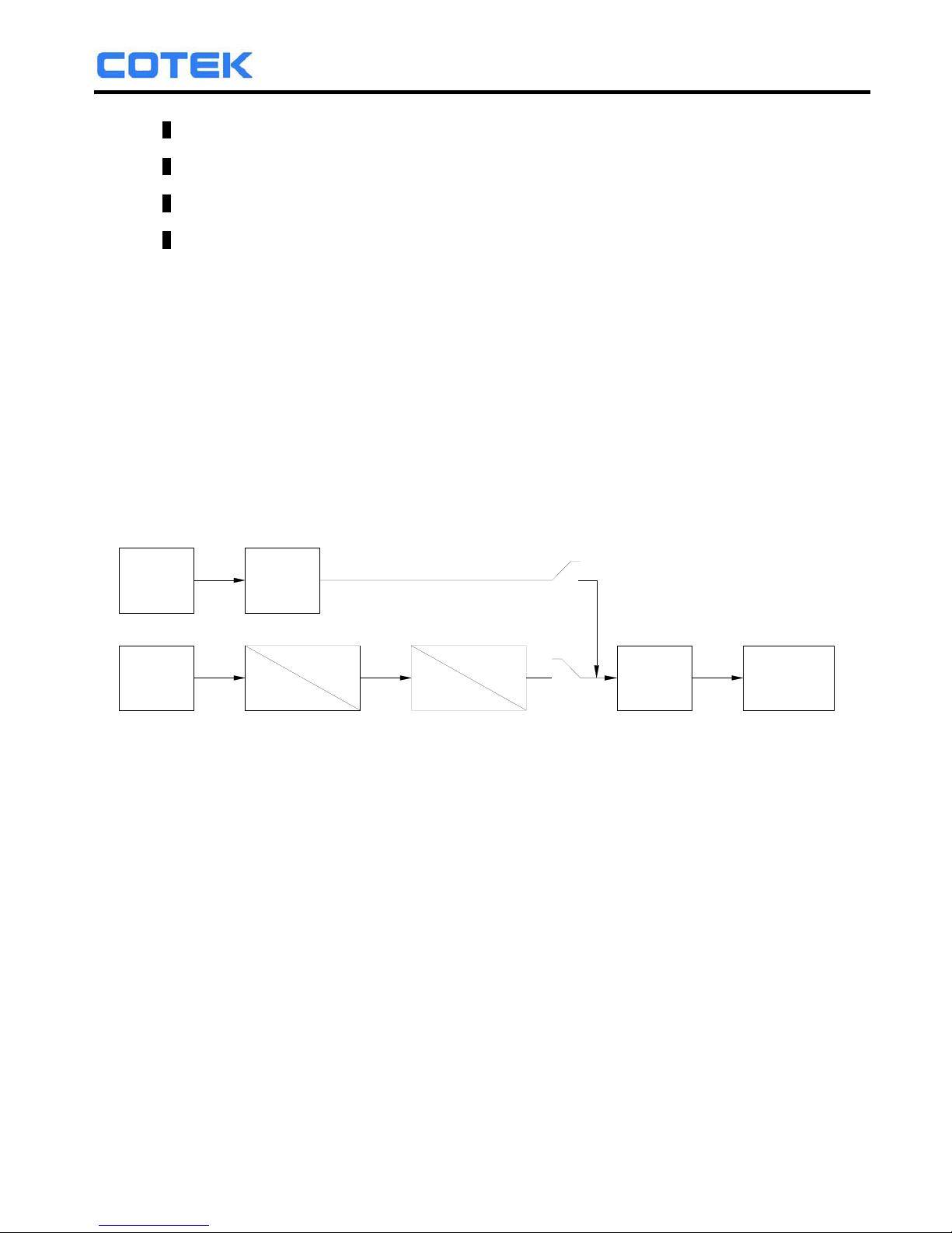
2-2. Block Diagram
AC GRID
INPUT
DC
INPUT
FILTER
DC
DC
AC
DC
FILTER
AC
OUTPUT
BYPASS RELAY
The inverter features IGBT technology which, minimizes weight and dimension,
while enhancing output short circuit reliability and overload capacity.
AC output voltage is provided in one of the two following modes:
1). From DC to AC Inverter Mode: (On-line Mode)
2). From AC Input Bypass Mode: (Off-line Mode)
Either mode is front panel programmable.
In the first option, Off-line mode, AC output power will be supplied through the AC
bypass mode in its normal operation. Upon AC input failure, output power will be
diverted through the DC to AC Inverter Mode. Once AC mains are restored, the unit
will revert from the Inverter Mode to the Bypass Mode.
In the second option, On-line mode, AC output power will be provided directly by
the inverter from the DC source. Should the DC source or inverter fail, the system
will transfer its output power through the bypass mode. Once the DC power source
is restored, the system will revert to the inverter mode.
6
Page 9
SR Series Inverter
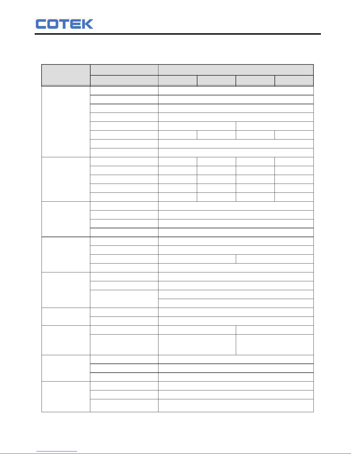
2-3. Electrical Performance
Note: The specifications are subject to change without notice.
7
Electrical
Specification
Item
Model No.
Output
Input
Continuous Output Power
Voltage
Input Over-Voltage Protection
Input Under-Voltage Protection
Voltage Range
No Load Current
LCD Panel
LED Indicator
Dry Contact Terminal
Remote Control Terminal
Input Protection
AC Output Protection
AC Input Protection
Temperature Protection
Relay Specification
Bypass relay selectable
Switching Time
Working Temperature
(Full load)
Storage
Failure Indicator
1000W
SR1000T-124 SR1000T-148 SR1000T-224 SR1000T-248
2000W
Yes, lpk
Pure Sine Wave (THD<2%)
24VDC
30~34VDC 30~34VDC60VDC Max. 60VDC Max.
18~22VDC 18~22VDC36~44VDC 36~44VDC
18~34VDC 18~34VDC36~60VDC 36~60VDC
1.4A 1.3A0.75A 0.7A
2 Lines LCD panel with keypad for navigation
Input voltage level, output load level and faulty status
By a relay
RJ-11
Over / Under voltage, reverse polarity (Internal fuse)
Short-circuit, overload
Shutdown (Internal temperature ≧ 65
o
C)
12 Amp circuit breaker
15Amp / 120VAC, 10Amp / 250VAC
On Line / Off Line (Haphazard, Normal, Exacting) selectable
From AC bypass mode (Off-line mode) : ≦ 20mS
From DC to AC inverter mode (On-line mode) : ≦ 8mS
0
o
C ~ 50oC
-30
o
C ~ 70oC
Buzzer alarm and dry contact
Switches On When
Safety Standards
EMC Standards
Switches Off When
Dimension
(WxHxD)
Packing
Application
Internal Temperature ≧ 55
o
C or Load ≧ 30%
Certified UL 60950-1 Certified EN 60950-1
Certified FCC Class B
Certified EN55022, EN61000-3-2,
EN61000-3-3, EN55024,
IEC61000-4-2,3,4,5,6,8,11
Internal Temperature ≦ 45
o
C and Load ≦ 20%
483 x 44 x 395 mm / 19.02 x 1.73 x 13.55 inch
7.46kg; 2pcs / 15.9kg / 1.74 CUFT
Focus on telecommunication (base-station), networking (data center) &
battery backup system.
6 Amp circuit breaker
48VDC 24VDC 48VDC
87% 88% 90% 91%
97~123VAC (User-selectable) 194~246VAC (User-selectable)
47~63Hz ± 0.5% (User-selectable)
1100W
Maximum Output Power
(3 Min)
Surge Power
Frequency
Output Voltage
Efficiency
(Full Load)
Short-Circuit Protection
Output Waveform
Signal and Control
Protection
Bypass Relay
Environment
Fan Operation &
Indicator
Others
Safety & EMC
Page 10
SR Series Inverter
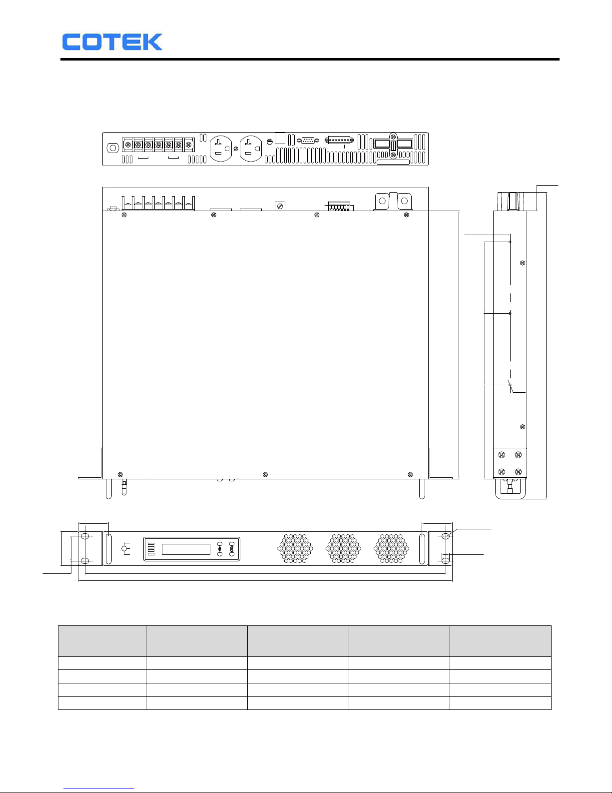
2-4. Mechanical Drawings
8
SR Series Inverter Ordering Information
Input
Voltage
Output Voltage
Nominal
Output Voltage
Range
Frequency
Range
Model
Number
SR1000T-124 24 VDC 110 VAC 100~120 VAC 47~63 Hz
SR1000T-224 24 VDC 230 VAC 200~240 VAC 47~63 Hz
SR1000T-148 48 VDC 110VAC 100~120 VAC 47~63 Hz
SR1000T-248 48 VDC 230VAC 200~240 VAC 47~63 Hz
ON
OFF
REMOTE
AC GRID
INVERTER
BYPASS
ALARM
PURE SINE WAVE INVERTER
GND
ENB
ENBNCNO
COM.
INV. FAILURE
RS-232
AC
OUTPUT
LN FG L N
AC OUTPUT
AC INPUT
AC INPUT
BREAKER
CHASSIS
GROUND
WARNING:
POS(+)NEG(-)
REVERSE POLARITY
WILL DAMAGE UNIT
420[16.54]
24[0.94]
21.8[0.86]
39.3[1.55]
5.9[0.23]
483[19.02]
465.0[18.31]
39.3[1.55]
R3.5[R0.14]
10.0[0.39]
44[1.73]
31.8[1.25]
M3*6
345[13.58]
395[15.55]
92.0[3.62] 92.0[3.62]120.0[4.72]
Page 11
SR Series Inverter
3. Installation and Maintenance
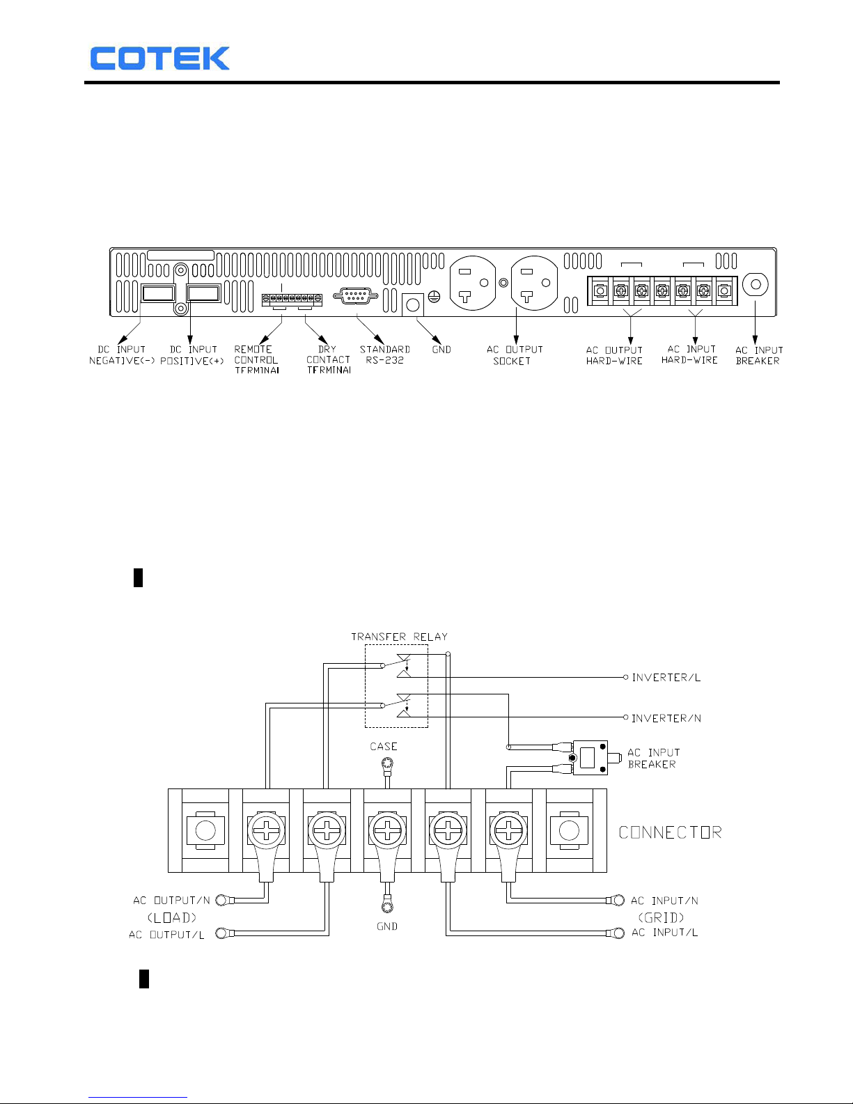
3-1. Rear Panel
REAR PANEL VIEW
3-1-1. AC Input Breaker:
The AC input circuit breaker protects the unit from overload. When an overload
condition occurs, the circuit breaker trips and disconnects the AC grid power
input. To reset it, push the circuit breaker button. The cause of tripping should
be ascertained and corrected before the unit is reset .
3-1-2. Hard-wire Installation (AC wiring connections):
AC input and AC output terminal
Connect AC output and AC input wiring to the Inverter terminals.
Please use the following information as your reference:
GND
ENB
ENB
NC
NO
COM.
INV. FAILURE
RS-232
AC
OUTPUT
N L FG L N
AC OUTPUT
AC INPUT
AC INPUT
BREAKER
CHASSIS
GROUND
WARNING:
POS(+)NEG(-)
REVERSE POLARITY
WILL DAMAGE UNIT
9
Page 12
SR Series Inverter
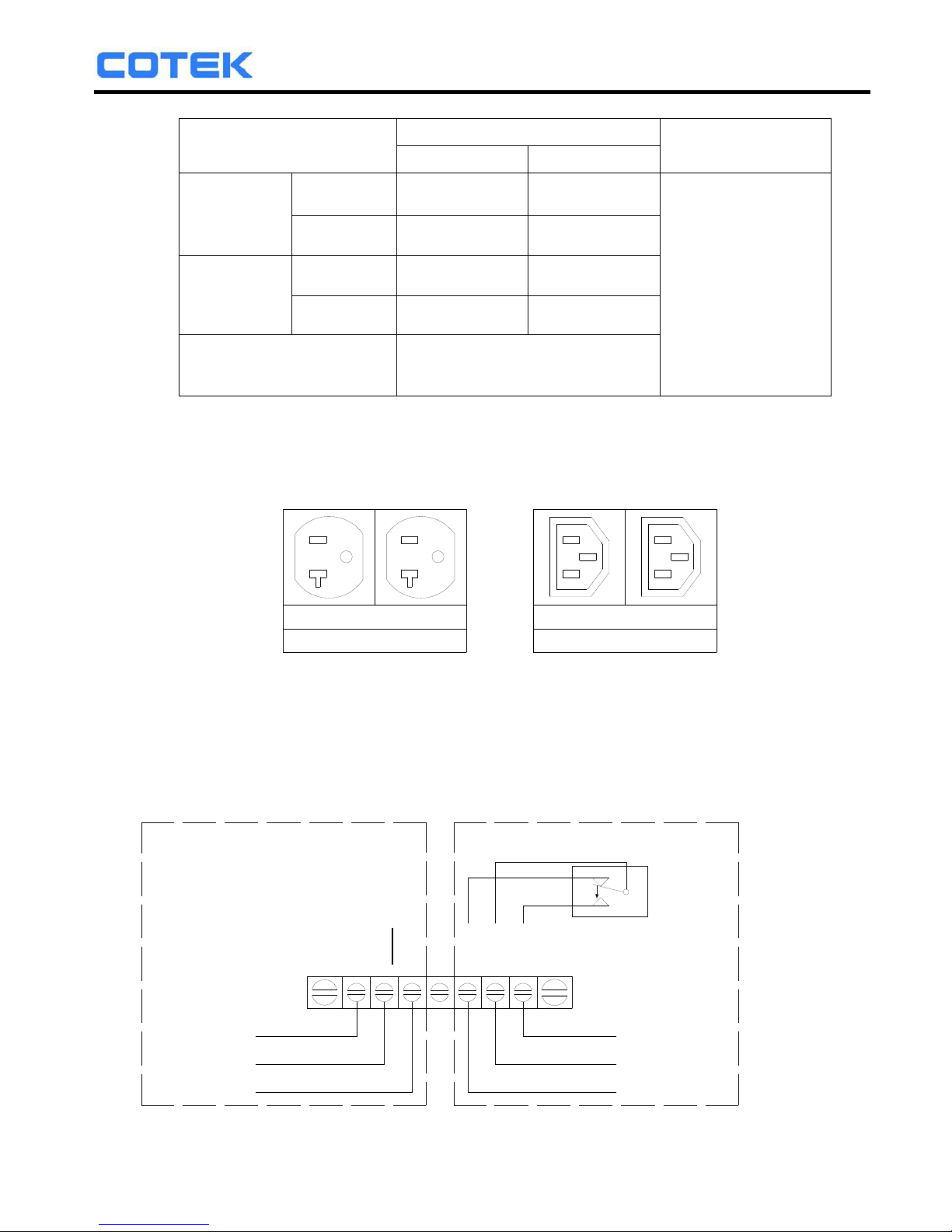
Terminal
Wire color
Wire length /
gauge
120 VAC 230 VAC
AC Output
Line (L) Black Brown
Within 16 feet /
AWG# 14~16
26~32 feet /
AWG# 12~14
Neutral (N) White Blue
AC Input
Line (L) Black Brown
Neutral (N) White Blue
Chassis Ground Green / Yellow or Bare copper
Note. Please double check and review all the connections to ensure that the
wires are connected to the correct terminals and that the connections are tight.
3-1-3. AC output socket:
110VAC
NEMA
230VAC
I.E.C 60320 C13
3-1-4. Chassis Ground: Must be connected to earth ground prior to
making any other connections to the equipment.
3-1-5. RS-232: Serial port monitoring and control through computer interface.
3-1-6. Remote control and Dry contact terminal:
Normally Open
RELAY
COM.
NO
NC
ENB
ENB
GND
Remote Control Terminal Dry Contact Terminal
Common
Normally Closed
GOUND
ENABLE -
ENABLE +
▌Remote Control Terminal:
10
Page 13
SR Series Inverter
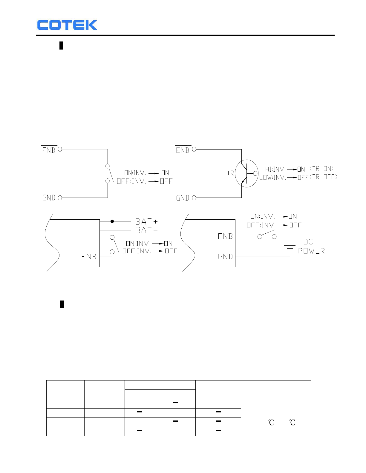
Remote Control Terminal:
1). Before installing the inverter, ensure that the main switch “OFF”.
2). Before using the remote function, ensure that the main switch pressed
toward “REMOTE”.
3). Ensure that the remote contacts are off.
4). Use 20 ~ 24 #AWG wire to connect the remote control terminals.
5). Remote control ON/OFF inverter setup status:
+
-
NOTE: At one time, only one remote function should used to control the inverter.
The maximum voltage value is 60VDC.
Dry Contact Terminals:
Dry contact terminals may be connected to a Form C relay for “FAULT”
indication. When “FAULT” occurs, the relay switches.
NOTE: Fault conditions include Input under/over voltage, Output Short Circuit,
Over Temperature, Over-load and, Fan Failure.
Specifications of the Relay
Maximum
Voltage
Load
Contact Rating Number of
operations
Operating/Storage
Temperature
N.O. N.C.
240 VAC Resistive 16 A 100,000
-30
~70
240 VAC Resistive 8 A
30 VDC Resistive 16 A
30 VDC Resistive 8 A
11
Page 14
SR Series Inverter
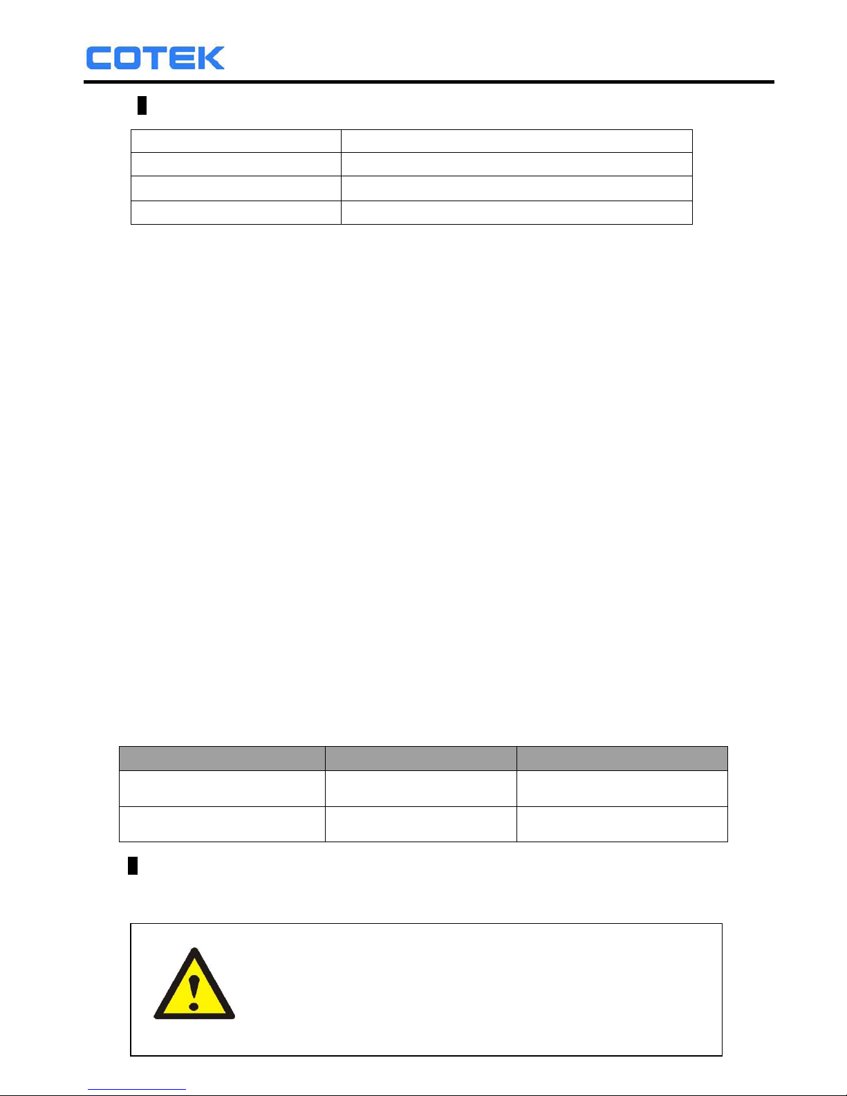
Remote Control Terminal:
Dry Contact Terminal Relay
COM. Common contact
N.C. Normally closed contact
N.O. Normally open contact
3-1-7. DC Input Connection:
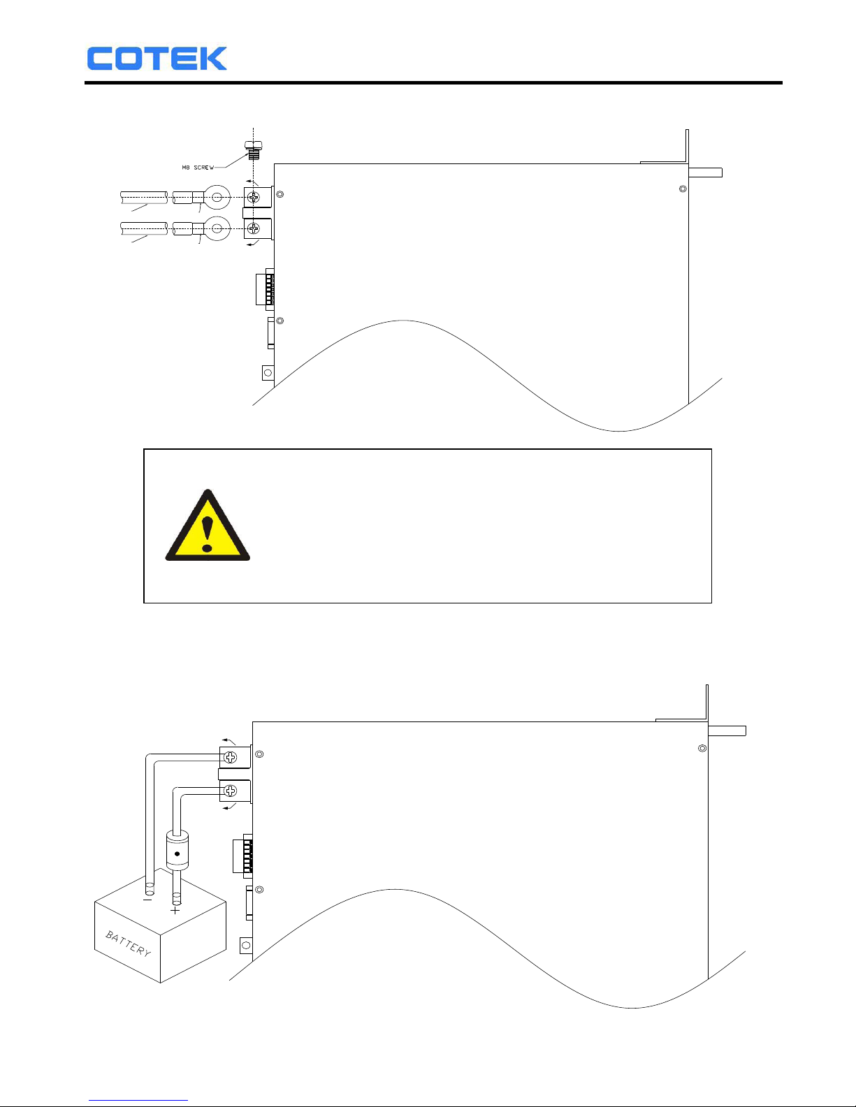
Follow the instructions to connect the battery cables to the DC input
terminals of the inverter. The cables should be as short as possible (less
than 6 feet / 1.8 meters ideally) so that they can handle the required
current in accordance with the Electrical Codes and Regulations. The size
of the cable should be thick enough to limit the voltage drop to less than
2% when carrying the maximum input current to prevent frequent low-input
voltage warnings, and shutdown. UVP (Under Voltage Protection) warning
may result if there is excessive voltage drop across the DC cables between
the batteries and the inverter.
Increasing your DC cable size will help improve the situation.
Batteries are capable of providing very large currents in case of short
circuit. In case there is a short circuit in the cable run between the batteries
and the input terminals of the inverter, it will result in overheating / melting
of the cables and consequent risk of fire and injury, To prevent possibility of
this hazard, use Very Fast Acting DC Fuse in line with the positive cable.
The fuse should be as close to the positive battery terminal as possible.
Use Bussmann ANN series fuses ( will also require Fuse Block 4164) or
equivalent.
The following sizes of cables and fuses are recommended for up to 6 ft.
distance between the batteries and the inverter. (Applies to both 120 VAC
and 230 VAC versions):
Model No Wire AWG Inline Fuse
# 4 80 A SR1000T-124 / 224
SR1000T-148 / 248 # 6 40 A
Connect DC input terminals to 24V / 48V battery or other DC power source.
[ + ] is positive, [ - ] is negative. Reverse polarity connection can blow the
internal fuse and may damage the inverter permanently.
WARNING!
Make sure that all the DC connections are tight (torque
to 9 – 10 ft-lbs, 11.7 – 13 Nm). Loose connections
could result in overheating and can be a potential
hazard.
12
Page 15
SR Series Inverter
RIN G TER MINA L
PVC WI RE
(AW G#4 - #6)
RIN G TER MINA L
PVC WI RE
(AW G#4 - #6)
NEG ATIVE-
POS ITIVE +
Also, only use high quality copper wire and keep the cable length short
which is a maximum of 3 - 6 feet.
INLINE FUSE
NEGATIV E-
PO SITI VE+
WARNING!
The recommended inline fuse should be installed as
close to the battery positive terminal as possible
Failure to use a fuse on the “+” cable running
Between the inverter and battery may cause
damage to the cable / inverter and will void warranty.
13
Page 16
SR Series Inverter
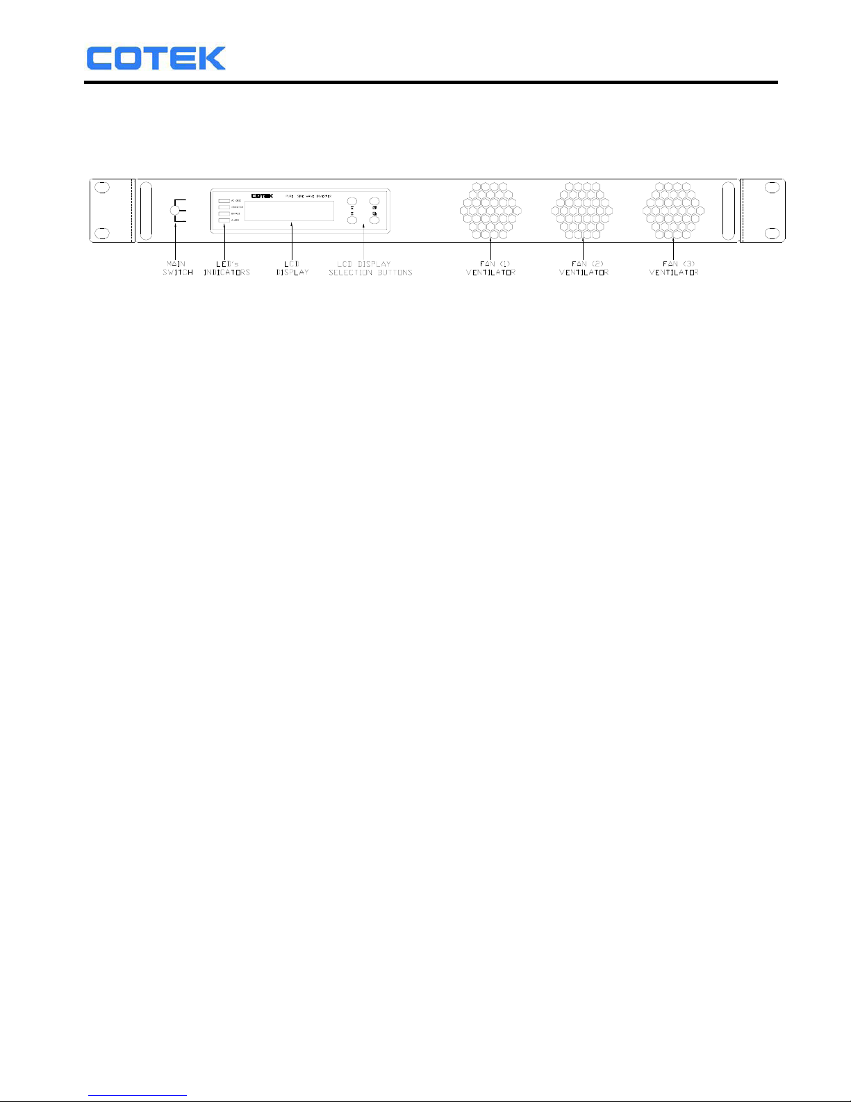
3-2. Front Panel
FRONT PANEL VIEW
ON
OFF
REMOTE
Vi =24.0 Vo=115
FQ=60.0 Io =8.5
3-2-1. Main Switch: These are the 3-stage rocker switches for turning on, turning off
and remote mode.
3-2-2. LED’s Indicators: See details in Section 5-1.
3-2-3. LCD Display Selection Buttons:
Data pertaining to the DC input voltage, AC output voltage, AC output
frequency, AC output current, etc. and system status can be shown
sequentially on the LCD display by pressing these buttons. Please refer to
chapter 5 for more information.
3-2-4. FAN ventilation grille (1)~(3): The fans behind the ventilation grilles provides
cooling. DOT NOT obstruct these vents!
3-3. Maintenance
3-3-1. Make sure that the fan vents are not blocked.
3-3-2. Use a vacuum cleaner to remove any dust from the fan area.
3-3-3. When cleaning the case or front panel, use a soft, dry cloth, only. If the case
or front panel is very dirty, use a neutral, non-abrasive detergent. Do not use
alcohol or ammonia based solutions.
3-3-4. Regular service, and relocation of the inverter, should be performed by a
qualified service technician.
3-3-5. Avoid spilling liquid on the inverter.
4. Operation:
4-1. Connecting the input power
Before making the DC input side connections, the main switch must
be “OFF”.
14
Page 17
SR Series Inverter
4-2. Connecting the loads
Calculate the total power consumption(W) of the output load. Make sure that
the total power consumption does not exceed the rated load.
Should the total load exceed the rated capacity of the inverter, remove the
non-critical. loads until the rated total has been reached.
4-3. Inverter Operation
Set the power switch to the “ON” position. The buzzer will sound “beep beep”.
The inverter will carry out self-diagnosis and, the LED’s will also appear various
colors. At the, same time the LCD will display ”SR-1000
INVERTER INITIALIATION”.
Finally, the buzzer will sound another “beep” and the “INVERTER” and
status LED’s will turn “Green”, The LCD Display will display “Vi, Vo, FQ, Io“.
THE, inverter will start operating normally.
Set the power switch to the “OFF” position. THE, inverter stops and all
the lights that are on will, go off.
4-4. Protections Features
Model
DC Input (VDC) Over Temperature Protection
Over Voltage Under
Voltage
Alarm
Under Voltage INTERIOR HEAT SINK
Shut-down Restart Shut-down Restart
Shutdown
Restart
Shutdown
Restart
24 V 30.1~34.1 28~32 19~23 18.1~22.1 23~27
65
45 105 75
5. Front LCD Panel – Display & Setup
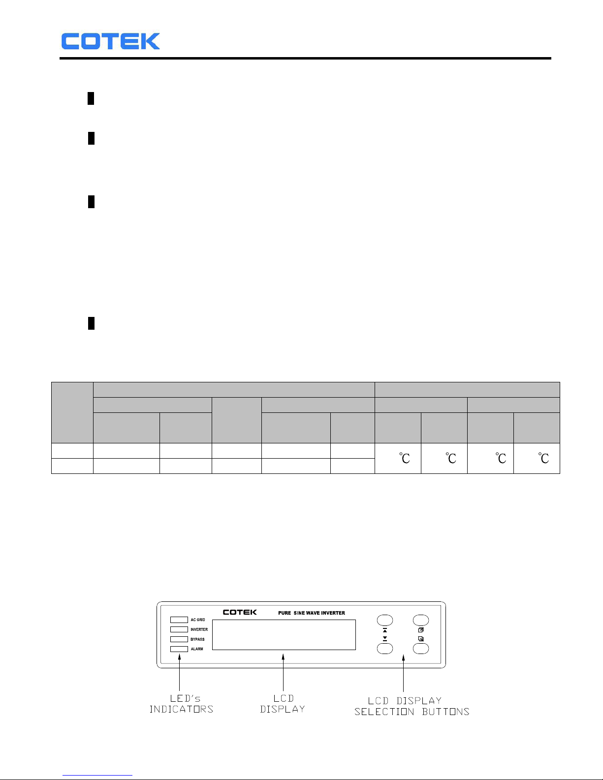
5-1. LCD Panel Indications
5-1-1. Set the Power Switch to the “ON” position. THE, inverter starts working
normally. The inverter will be operating in normal condition when either
of the following messages are displayed on the LCD screen:
FQ=60.0 Io =8.5
Vi =24.0 Vo=115
48 V 56~60 38~46 36.1~44.1 46~5460.1
15
Page 18
SR Series Inverter
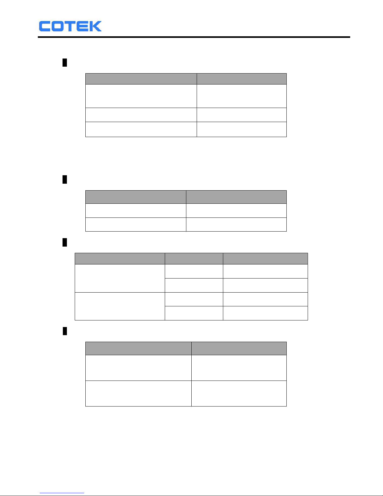
5-1-2. LED Indications:
AC GRID: Displays AC input status.
AC Input LED Status
AC input and DC-AC Inverter
Output are Synchronous
Green
AC input ON Orange
AC input OFF Off
Note. Synchronous means that the: grid AC input frequency and DC-AC
inverter output frequency or phase are the same (See details in
Section 5-3-3).
INVERTER: Displays DC-AC inverter status.
DC-AC Inverter LED Status
Power OK Green
Power Not Good Red
BYPASS: Displays Transfer Switch status.
Bypass
LED Status AC Output (Load)
From DC-AC inverter
(On-line Mode)
Orange AC Input
Off DC-AC Inverter
From AC input bypass
(Off-line Mode)
Green AC Input
Off DC-AC Inverter
ALARM: Displays status of the Failure Alarm.
Alarm LED Status
Over/Under Alarm
/FAN Alarm
Orange
Set alarm in the inverter to
operate normally
Off
NOTE. For instructions on setting the alarm, see details in Section 5-3.
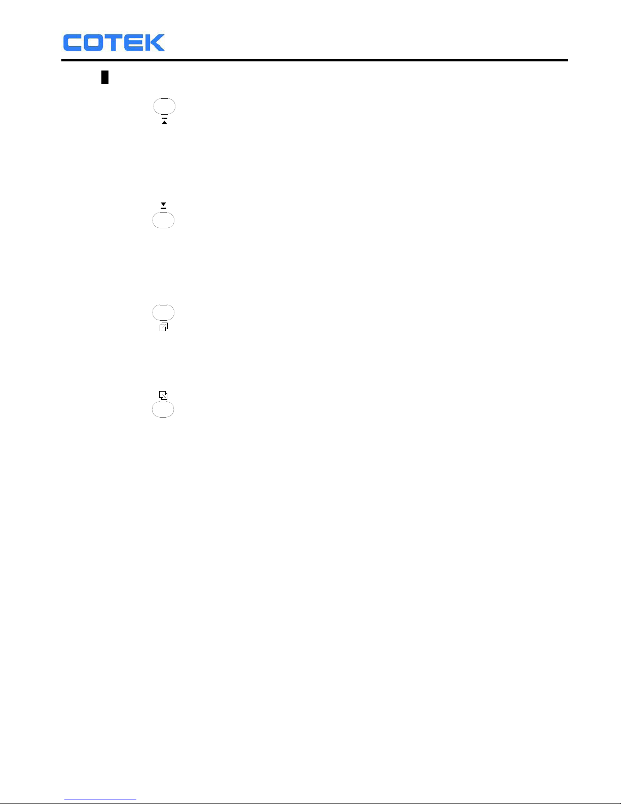
5-1-3. LCD Display Selection Buttons:
16
Page 19
SR Series Inverter
Function of Various Keys :
Function <Up>: You can use the “up” button to scroll through the menus.
or to select the value for set up under setting mode.
Function <Down>: You can use the “Down” button to scroll through the
menus or to select the value for set up under setting
mode.
Function <Page Up>: You can use the “Page Up” button to scroll through the
menus.
Function <Page Down>: You can use the “Page Down” button to scroll
through the menus.
Function <Enter Setup Menu>: Press the button longer than 2 seconds,
The inverter will change to “Setup Menu Mode”
which appears on the LCD screen for the user
to set functions.
Function <Enter>: Confirms a selection or value.
5-1-4. LCD Display: Displays inverter’s operational status.
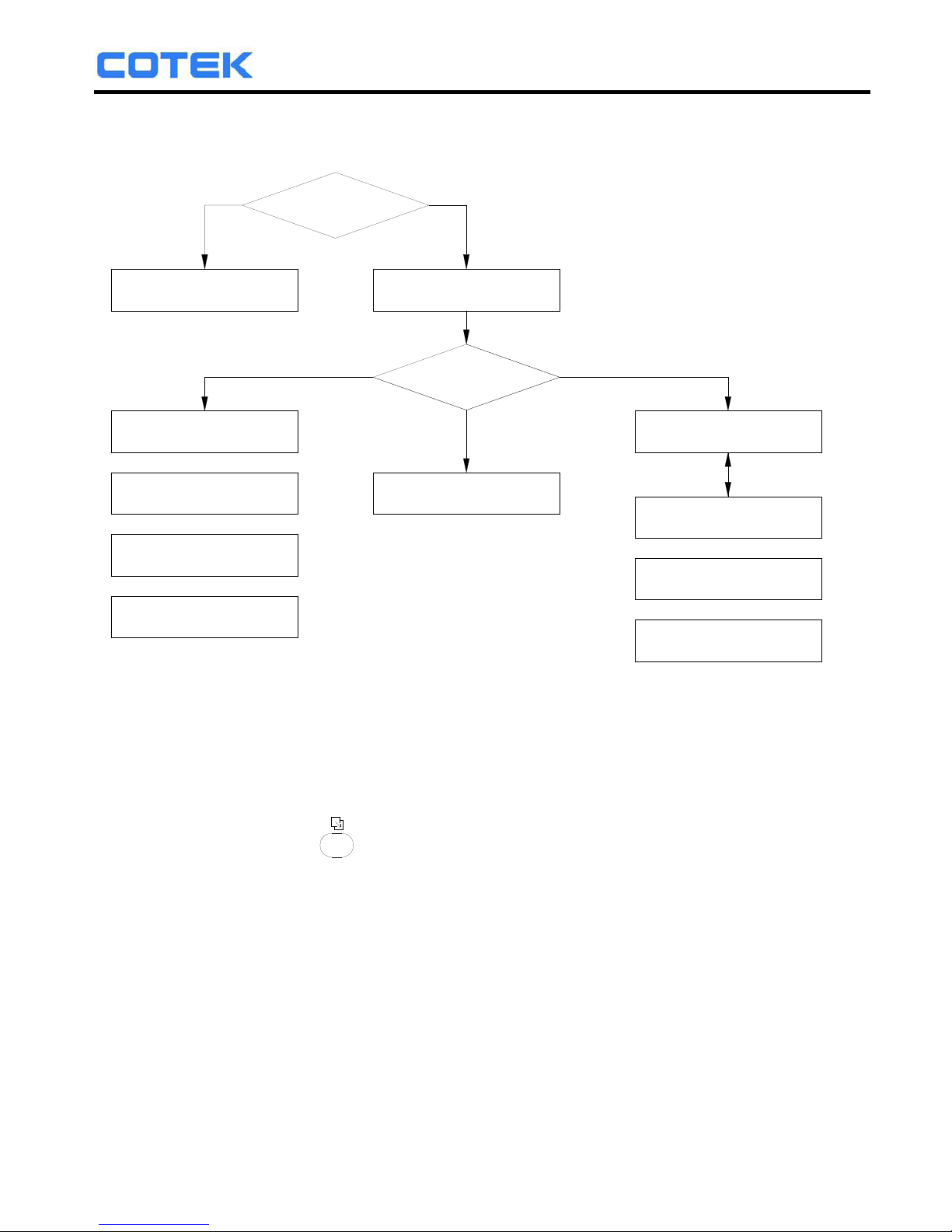
5-2. Startup Sequence and Standby Status
5-2-1. Once turn on the inverter. The display shows “SR-1000 INVERTER
INITIALIATION..”, then checks the inverter.
Status flow is as follows:
17
Page 20
SR Series Inverter
Fan Failure!!
Alert:
Overload!!
Alert:
OR
OR
1Sec
Exchange
Alert:
Undervoltage!!
Vi =XX.X Vo=XXX
FQ=XX.X Io =X.X
FQ=XX.X Io =X.X
Vi =XX.X Vo=XXX
ALARM
OK
Vi =XX.X
OLP Shutdown
OR
Vi =XX.X
OTP Shutdown
OR
OR
OVP Shutdown
Vi =XX.X
Vi =XX.X
UVP Shutdown
FAILURE
CHECK INVERTER
SR-1000 INVERTER
INITIALIATION ..
ONOFF
POWER SWITCH
5-3. Setup Menu – Operation and Instructions
Entering Setup Menu:
Press
Button longer than 2 seconds. The inverter, enters the
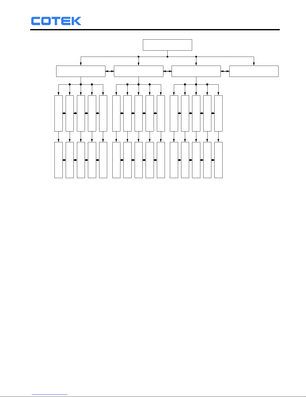
Setup Menus consisting of three layers:
(1)Select Menu Heading: (2)Select Menu Item: (3)Setting Value:
18
Page 21
SR Series Inverter
Vi =XX.X Vo=XXX
FQ=XX.X Io =X.X
Main Menu:
Select
Menu:
User interface
Select Menu:
I/P Parameter
Select Menu:
O/P Parameter
Select Menu:
RST to default
Select Menu:
Select Item:
LCD Contrast
Select
Item:
Select Item:
LCD Auto-off
Select Item
:
RS232 Baudrate
Select Item:
Buzzer Setting
Select Item:
Alert Setting
0 1 2 3 4 6
7
8 9 10 11 12 13 14 15
Function
Code:
OVP Setting
Select Item:
OVP Recovery
Select Item:
UVP Setting
Select Item:
UVP Recovery
Select Item:
UV Alarm
Select Item
:
O/P Voltage
Select Item:
O/P Frequency
Select Item:
Sync Frequency
Select Item
:
Bypass relay
Select Item:
Overload Alarm
Select Item:
50%
LCD Contrast:
Setting
Value:
LCD Auto-off:
120S
RS232 Baudrate:
4800
Buzzer Setting:
MSG , Alert , SHDN
Alert Setting:
Alert , SHDN
OVP Setting:
32.00V
30.00V
OVO Recovery:
20.00V
UVP Setting:
25.00V
UVP Recovery:
21.00V
UV Alarm:
O/P Voltage:
230V
O/P Frequency:
50.00Hz
Sync Frequency:
7.00Hz
Bypass relay:
On-line
Overload Alarm:
100%
5-3-1. User interface (Select Menu):
0). LCD Contrast: Sets LCD screen contrast.
Default=50%
Setting Range= 0%~100%
1). LCD Auto-off: Sets LCD auto off timer.
Default=120 seconds.
Setting Range= Disable~250 seconds.
2). RS232 Baud-rate: Sets standard RS-232 Baud-rate.
Default=4800
Setting Range= 1200/2400/4800/9600
3). Buzzer Setting: Sets the internal buzzer sound ON/OFF.
When setting, the LCD screen display,
Buzzer “ON”, Buzzer “OFF”.
Default=MSG, Alert, SHDN
Setting Range= Disable / Shutdown / Alert
/ Alert, SHDN / Message
/ Message, SHDN / Message, Alert
/ MSG, Alert, SHDN
19
Page 22
SR Series Inverter
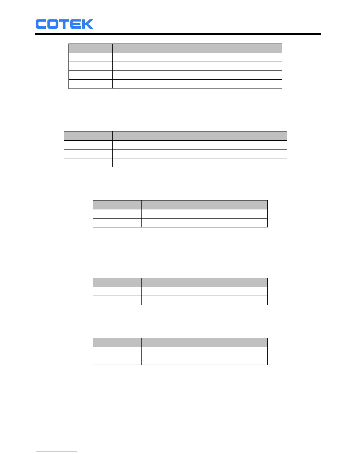
Menu Status Buzzer
Message Power ON or Push Keypad ON
Alert FAN Fail or UV Alarm or Overload Alarm ON
Shutdown OVP or UVP or OLP or OTP ON
Disable Any OFF
4). Alert Setup: When alert occurs, the internal Dry Contact Relay will
open / close. (See details in Section 3-1-6)
Default= Alert, SHDN
Setting Range= Disable / Shutdown / Alert / Alert, SHDN
Menu Status Relay
Alert FAN Fail or UV Alarm or Overload Alarm ON
Shutdown OVP or UVP or OLP or OTP ON
Disable Any OFF
5-3-2. I/P Parameter (Select Menu):
6). OVP Setting: Sets the Over Voltage Protection (OVP) and shutdown.
Default= 34 VDC for 24 V Model, 60 VDC for 48 V Model
Model Setting Value Range
24 V 30 VDC ~ 34 VDC
48 V
7). OVP Recovery: When the DC input voltage is higher than the OVP
setting, the inverter shuts-down; Once the input voltage
falls below the set OVP value, the inverter will
automatically restart.
Default= 30 VDC for 24 V Model, 56 VDC for 48 V Model
Model Setting Value Range
24 V 28 VDC ~ 32 VDC
48 V 56 VDC ~ 60 VDC
8). UVP Setting: Setting the inverter’s Under Voltage Protection (UVP) and
Shutdown.
Default= 18 VDC for 24 V Model, 36 VDC for 48 V Model
Model Setting Value Range
24 V 18 VDC ~ 22 VDC
48 V 36 VDC ~ 44 VDC
9). UVP Recovery: When the DC input voltage is below the set UVP value
the inverter shuts-down; Once the input voltage rises
above the set UVP value, the inverter will automatically
restart.
Default= 25 VDC for 24 V Model, 50 VDC for 48 V Model
60 VDC MAX.
20
Page 23
SR Series Inverter
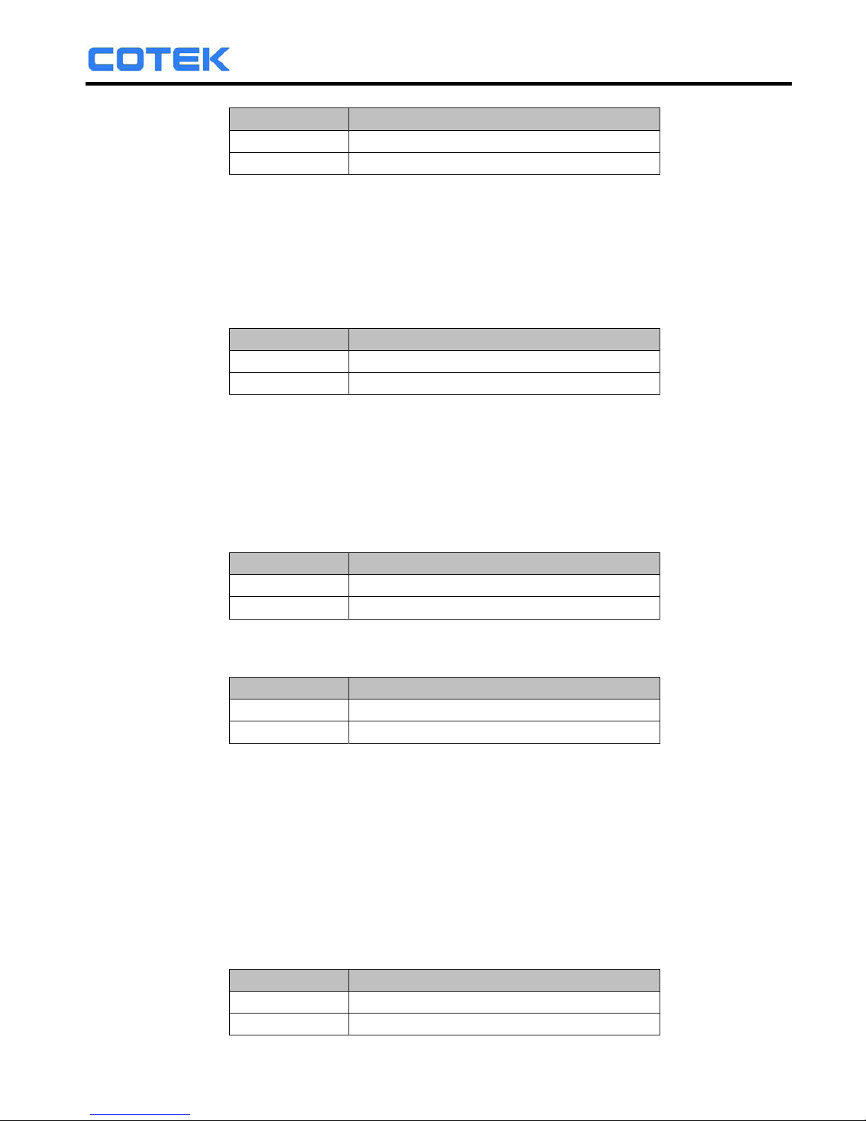
Model Setting Value Range
24 V 23 VDC ~ 27 VDC
48 V 46 VDC ~ 54 VDC
10). UV Alarm: Sets Under Voltage (UV) alarm. When the input voltage is
lower than the set value, the unit will sound “beep” to remind
that the unit is going to shutdown. At the meantime, the
contact in the internal Dry Contact Relay will open / close
(See details in Section 3-1-6).
Default= 21 VDC for 24 V Model, 42 VDC for 48 V Model
Model Setting Value Range
24 V 19 VDC ~ 23 VDC
48 V 38 VDC ~ 46 VDC
NOTE. The value of voltage set for the “UV Alarm” should be equal to or
higher than the value set for “UVP” or else the unit will shutdown
without any audible warning.
5-3-3. O/P Parameters:
11). O/P Voltage: Set the inverter output voltage.
Default= 110 VAC for 110 V Model, 230 VAC for 220 V Model
Model Setting Value Range
110 V 97 VAC ~ 123 VAC
220 V 194 VAC ~ 246 VAC
12). O/P Frequency: Set the inverter output frequency.
Default= 60 Hz for 110 V Model, 50 Hz for 220 V Model.
Model Setting Value Range
110 V 47 Hz ~ 63 Hz
220 V 47 Hz ~ 63 Hz
13). Sync Frequency: Sets the AC output synchronous frequency.
Example: AC input= 230 VAC / 50Hz,User setting Value= 7Hz
When the DC to AC inverter “Frequency” is
within The Range of 43 Hz~57 Hz, the internal
transfer relay will operate normally. When the
“Frequency” is less than 43 Hz or more than 58 Hz,
the internal transfer relay will de-energize.
(See details in Section 2-2)
Default= 0.1Hz ~ 7Hz.
Model Setting Value Range
110 V 0.1 Hz ~ 7 Hz
230 V 0.1 Hz ~ 7 Hz
21
Page 24
SR Series Inverter
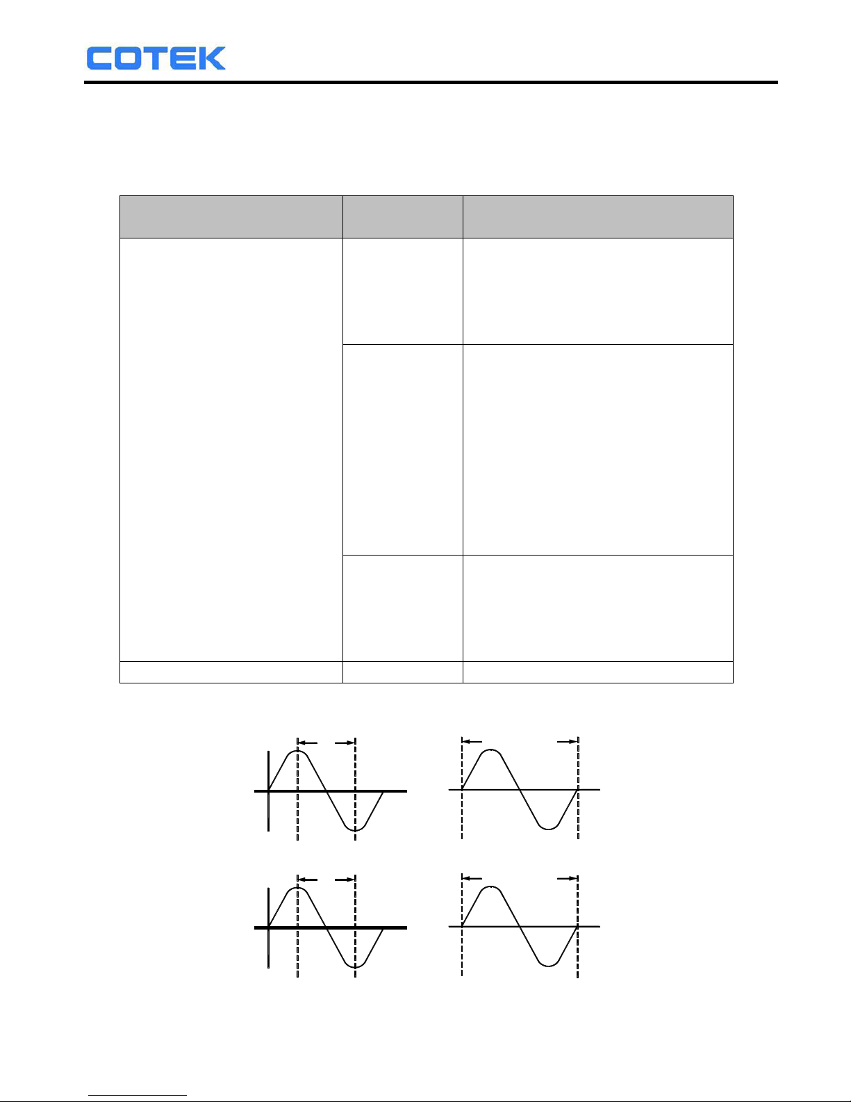
14). Bypass Relay: The setup is provided in one of the following two ways:
On line Mode or Off line Mode (Exacting, Normal,
Haphazard).
Default= Normal (Off line).
Mode Menu
Transfer Relay
Switching Feature
OFF LINE
(See details in Section 5-3)
Exacting
The transfer relay will switch
“ON” or “OFF” based on
conformance to, the Phase and
Sync Frequency window that
has been set (Function Code 13)
Normal
The transfer relay will be “ON” if
AC input (Grid) power is
available. The DC-AC inverter
will remain synchronized and
Phase with the incoming AC
power (Grid). The relay will NOT
switch off if the grid frequency is
beyond the range set under
Sync Frequency window
(Function Code 13).
Haphazard
The transfer relay will switch
“ON” or “OFF”. Conformance to,
phase and frequency
synchronization will not be
considered.
ON LINE --------- (See details in Section 5-3)
F
Frequency
Synch ronous
DC -AC inv erter
AC input (G RID)
F
Phase
AC input (G RID)
DC -AC inv erter
Phase
Synchronous
Phase
22
Page 25
SR Series Inverter
15). Overload Alarm: Sets the overload alarm. When the output power is
higher than the set value, the unit will sound “beep”
to remind that the unit is going to shutdown. At the
same time, the internal Dry Contact Relay will
open/close (See details in Section 3-1-6).
Default= 100%
Setting range= 50%~110%
6. RS-232 Communication and Operation
6-1. Operation of the RS-232 Serial Port:
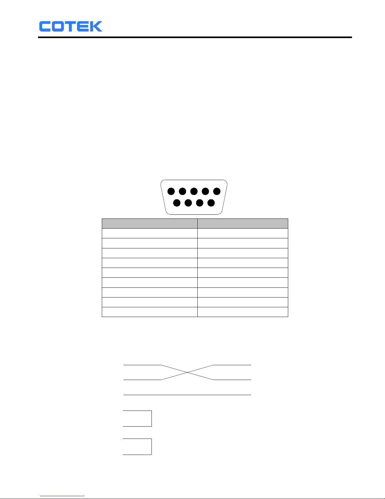
6-1-1. This unit uses a standard 9-Pole D connector and three of the RS232 signal
lines:
1 2 3 4 5
6 7 8 9
Signal description PIN
N.C 1
RXD 2
TXD 3
DTR 4
GND 5
DSR 6
RTS 7
CTS 8
N.C 9
6-1-2. The connection between this unit and the computer is as follows:
Computer
Power Inverter
RXD
GND
DXTDXT
GND
RXD
DSR
RTS
DTR
CTS
23
Page 26

SR Series Inverter
6-1-3. The RS232 interface of this unit employs ASCII code to implement the
asynchronous serial transmission control.
The byte structure is START-BIP – 8 BIT DATA-STOP BIT.
Baud rate: 1200/2400/4800/9600(See details in Section 5-3-1).
6-1-4. Coupled with PC software application port. Operation is as detailed in
Section 6-2.
6-2. Interface Commands:
The buffer size used for the RS232 port is 12-byte. This unit will ignore all bytes
more than this value. During transmission, this unit will indicate it is ready to
receive data from computer by this DTR line. A computer has to check the DTR
line before sending any information to this unit. This unit is normally always
ready to receive data while operating. When a LF character (ASCII code 0AH)
is received, this unit would finish the receiving by clearing the DTR status and
begin to interpret the received information. The unit would execute the received
command (AND/OR data) if it is correct. Irrespective of whether the command is
accepted or not, the unit will always send back a response signal to the
computer and set DTR to ready for receiving more incoming information.
6-2-1. The Baud-rate of the RS232 interface can be set with the help of the Setup
Menu (See details in Section 5-3-1).
Note. You have to reset the unit after adjustment to activate the new setting.
6-3. Example of RS232 Operation:
6-3-1. RS232 command:
Command format:
This unit uses high-level language commands with a CR (0DH) and
LF (0AH) as the end of the command.
The system would interpret and execute the command only after these two
characters are received. After the unit execute the command, it would send
a response string to the computer. The response string is as follows:
= > CR LF: Command executed successfully
? > CR LF: Command error, not accepted
! > CR LF: Command correct but execution error (e.g. parameters out of
range).
If the command needs any information from the unit, the unit would send
the information back to the computer (with CR and LF) and then send the
response string to the computer.
24
Page 27

SR Series Inverter
6-3-2. Command format:
This unit supports the following command format.
There should always be a CR (0DH) and a LF (0AH) appended to the
command while sending the command to this unit.
1). Command to switch the Power ON/OFF:
Format: Power <value>
Example: A space (ASCII code 20H) is needed between Power and
<value>.
<value> can be one of the following.
“0”: Power off
“1”: Power on
2). Command to query the Output Frequency:
Format: FRQ?
After “Enter”, the unit’s “Output Frequency” appears on the PC screen.
3). Command to query the Output Voltage:
Format: VOL?
After “Enter”, the unit’s “Output Voltage” appears on the PC screen.
4). Command to query the Output Current:
Format: AMP?
After “Enter”, the unit’s “Output Current” appears on the PC screen.
5). Command to query the Input Battery Voltage:
Format: BAT?
After “Enter”, the unit’s “Input Voltage” appears on the PC screen.
6-3-3. Command for accessing Setup Menus and adjusting values:
1). Select the Setup Menus with the help of Function Codes:
Format: FUNC <Function Code>
After “Enter”, the Setup Menu for the Function Code will be called.
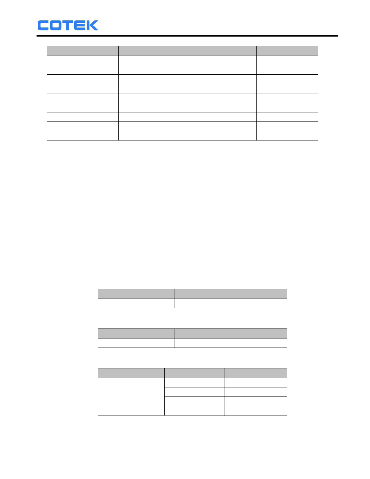
The <Function Code>= 0~17, as follows:
25
Page 28
SR Series Inverter
<Function Code> Setting Menu <Function Code> Setting Menus
0 LCD Contrast 9 UVP Recovery
1 LCD Auto-off 10 UV Alarm
2 RS232 Baud-rate 11 O/P Voltage
3 Buzzer Setting 12 O/P Frequency
4 Alert Setting 13 Sync Frequency
5 NOT USED 14 Bypass Relay
6 OVP Setting 15 Overload Alarm
7 OVP Recovery 16 NOT USED
8 UVP Setting 17 NOT USED
2). Command to query the Functions No:
Format: FUNC?
After “Enter”, the unit’s “Function Code” appears on the PC screen.
3). Command to query the set value of the Function:
Format: SETT?
After “Enter”, the existing set value of the function appears on the
PC screen.
4). Command to set or adjust the value of the Function:
Format: SETT <value>
After “Enter”, the new value of the Function is set Choose the
<value> of the function as follows:
FUNC 0: LCD Contrast
Setting Menu SETT <value>
LCD Contrast 0~100
FUNC 1: LCD Auto-off
Setting Menu SETT <value>
LCD Auto-off Disable~250
FUNC 2: RS232 Baud rate
Setting Menu SETT <value> Baud rate
RS-232
Baud rate
0 1200
1 2400
2 4800
3 9600
26
Page 29
SR Series Inverter
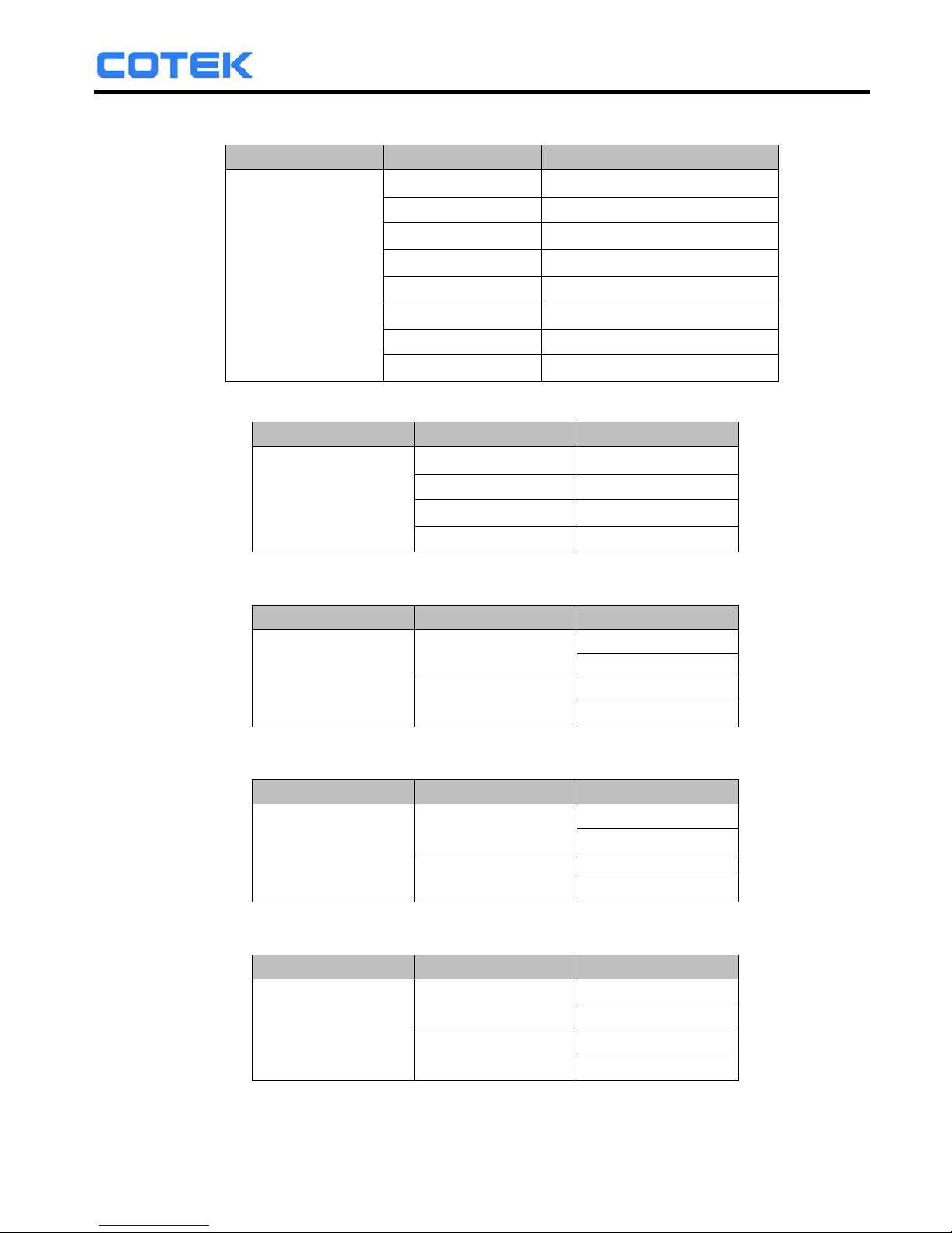
FUNC 3: Buzzer Setting
Setting Menu SETT <value> Buzzer (Beep sound)
Buzzer Setting
0 Disable
1 Shutdown
2 Alert
3 Alert , SHDN
4 Message
5 Message , SHDN
6 Message , Alert
7 Msg , Alert , SHDN
FUNC 4: Alert Setting
Setting Menu SETT <value> Alert
Alert Setting
0 Disable
1 Shutdown
2 Alert
3 Alert , SHDW
FUNC 6: OVP Setting
Setting Menu SETT <value> Model
OVP Setting
30~34
60 MAX.
SR1000T-124
SR1000T-224
SR1000T-148
SR1000T-248
FUNC 7: OVP Recovery
Setting Menu SETT <value> Model
OVP Recovery
28~32
SR1000T-124
SR1000T-224
56~60
SR1000T-148
SR1000T-248
FUNC 8: UVP Setting
Setting Menu SETT <value> Model
UVP Setting
18~22
36~44
SR1000T-124
SR1000T-224
SR1000T-148
SR1000T-248
27
Page 30
SR Series Inverter
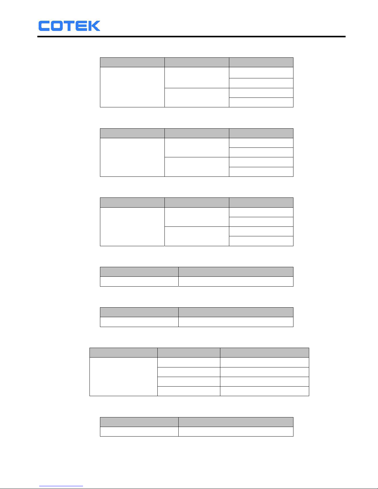
FUNC 9: UVP Recovery
Setting Menu
SETT <value> Model
UVP Recovery
23~27
46~54
SR1000T-124
SR1000T-224
SR1000T-148
SR1000T-248
FUNC 10: UV Alarm
Setting Menu
SETT <value> Model
UV Alert
19~23
38~46
SR1000T-124
SR1000T-224
SR1000T-148
SR1000T-248
FUNC 11: O/P Voltage
Setting Menu
SETT <value> Model
O/P Voltage
97~123
SR1000T-124
SR1000T-148
194~246
SR1000T-224
SR1000T-248
FUNC 12: O/P Frequency
Setting Menu
SETT <value>
O/P Frequency
47~63
FUNC 13: Sync Frequency
Setting Menu
SETT <value>
Sync Frequency
0.1~7
FUNC 14: Bypass Relay
Setting Menu
SETT <value> Mode
Bypass Relay
0 ON LINE
1 Haphazard(OFF LINE)
2 Normal(OFF LINE)
3 Exacting(OFF LINE)
FUNC 15: Overload Alarm
Setting Menu
SETT <value>
Overload Alarm 50~110
28
Page 31
SR Series Inverter
7. Information
7-1. Troubleshooting
Problems and Symptoms Possible Cause Solutions
No AC Power “Output”
a. LCD Panel Display
“OLP Shutdown”
Short circuit , wiring
error. over loading.
Check AC wiring for
short circuit .
Reduce load.
b. LCD Panel Display
“OVP Shutdown”
Over input voltage
(OVP)
Check input voltage
Reduce input voltage
c. LCD Panel Display
“UVP Shutdown”
Low input voltage.
(UVP)
Recharge battery.
Check connections
and cables.
d. LCD Panel Display
“OTP shutdown”
Thermal shutdown.
(OTP)
Improve ventilation.
Make sure ventilation,
grilles / slots of the
inverter are not
obstructed. Lower
ambient temperature.
7-2. Warranty
We guarantee this product against defects in materials and workmanship for
a period of 24 months from the date of purchase and will repair or replace
any defective power inverters if you directly returned them to us with
postage paid.
Please note that Cotek is only responsible for ensuring our products are
operational before delivering. This warranty will be considered void if the
unit has been misused, altered, or accidentally damaged. Cotek is not liable
for anything that occurs as a result of the user’s fault.
WARNING:
Do not open or disassemble the SR series Inverter.
Attempting to service the unit may cause risk of
electrical shock or fire.
29
Page 32

No. 33, Sec. 2, Renhe Rd., Daxi Township, Taoyuan County 33548, Taiwan
Phone
+886-3-3891999 FAX +886-3-3802333
E-mail
[email protected] http // www.cotek.com.tw
2014.11 A1
 Loading...