

Page 1

SN-1 User’s Manual
SNMP Module for COTEK SR Series
Page 2

Table of Content
1. INTRODUCTION
1-1. Main features 1
1-2. Hardware introduction 1
1-3. How to use Web-Server 2
1-4. SNMP V2C Description 7
2. INSTALLATION AND OPERATION 9
2-1. Installation of SN-1 9
2-2. Connecting from SN-1 to PC 9
2-3. Reset SN-1 to Default Value 10
3. TROUBLESHOOTING 11
4. WARRANTY 11
Page 3
1
1. Introduction
1-1. Main features
SNMP : SN-1’s version is V2C. It can be connected to system with NMS, to
set up and monitor SR-Host parameters.
Web-Server : Using the browser to set up and monitor SR-Host parameters.
1-2. Hardware introduction
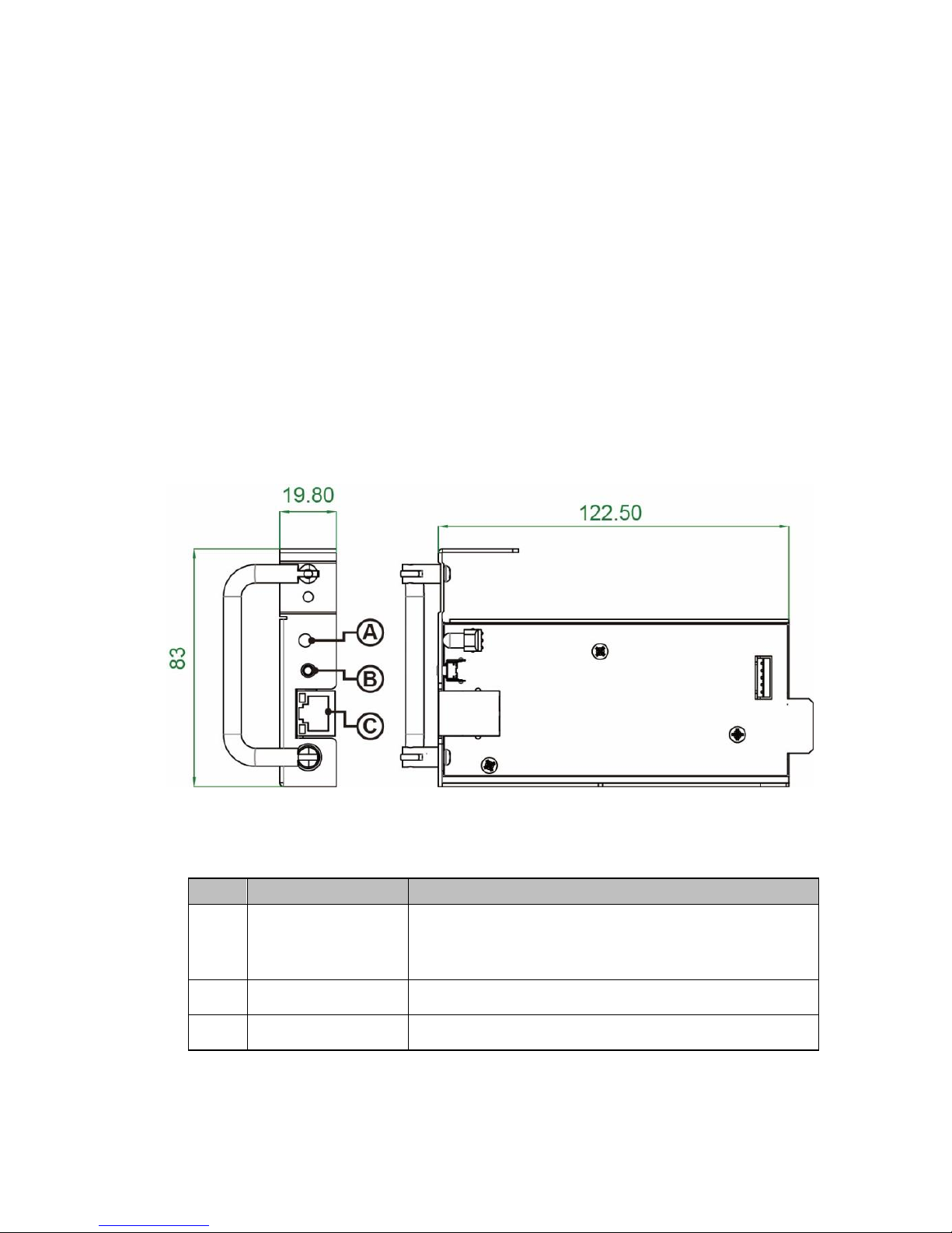
Description
Function
A
LED light
To display below operation status:
Green : Communicate with SR-Host successfully
Red : Fail to communicate with SR-Host
B
Reset Button
Go back to SN-1 default settings
C
RJ45
Connect to PC locally
Table 2.Panel introduction and terminal description
Fig. 1 Panel introduction (in mm)
Page 4
2
1-3. How to use Web-Server
1-3-1 Web-Server introduction
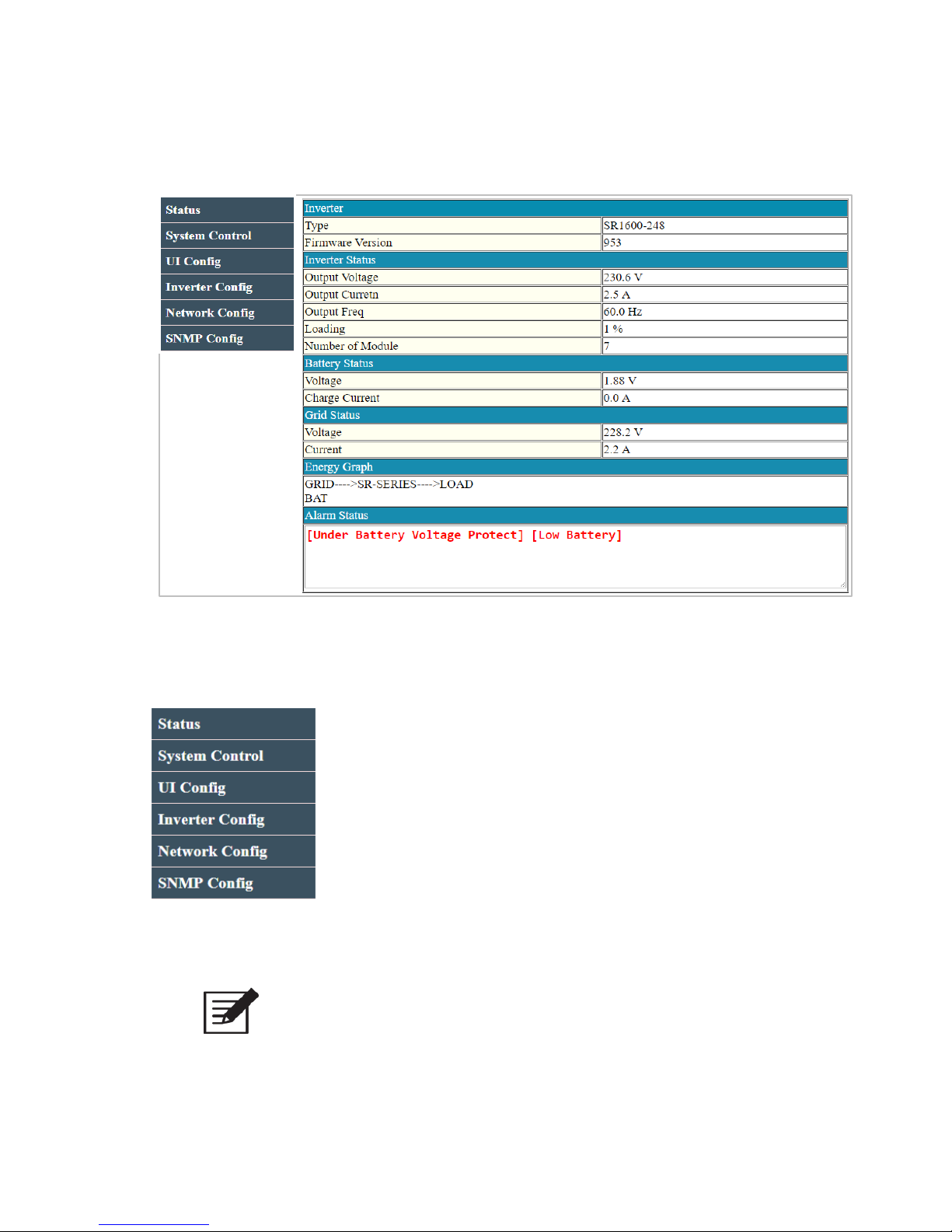
Fig. 2 Web-Server
Main menu item description:
Status: To display SR-Host status *SR-Host:SR-1600、SRC-2500…
System Control: system output control
UI Configuration: RS232/ Interface language/ Login password
Inverter Configuration: Inverter parameter (settings ex.OVP/UVP…)
Network Configuration: SNMP network settings (DHCP/IP…)
SNMP Configuration: Community Name setup for SNMP V2C
Note! Note! Default login name: admin
Default login password: 0000
Page 5
3
1-3-2 Status Page
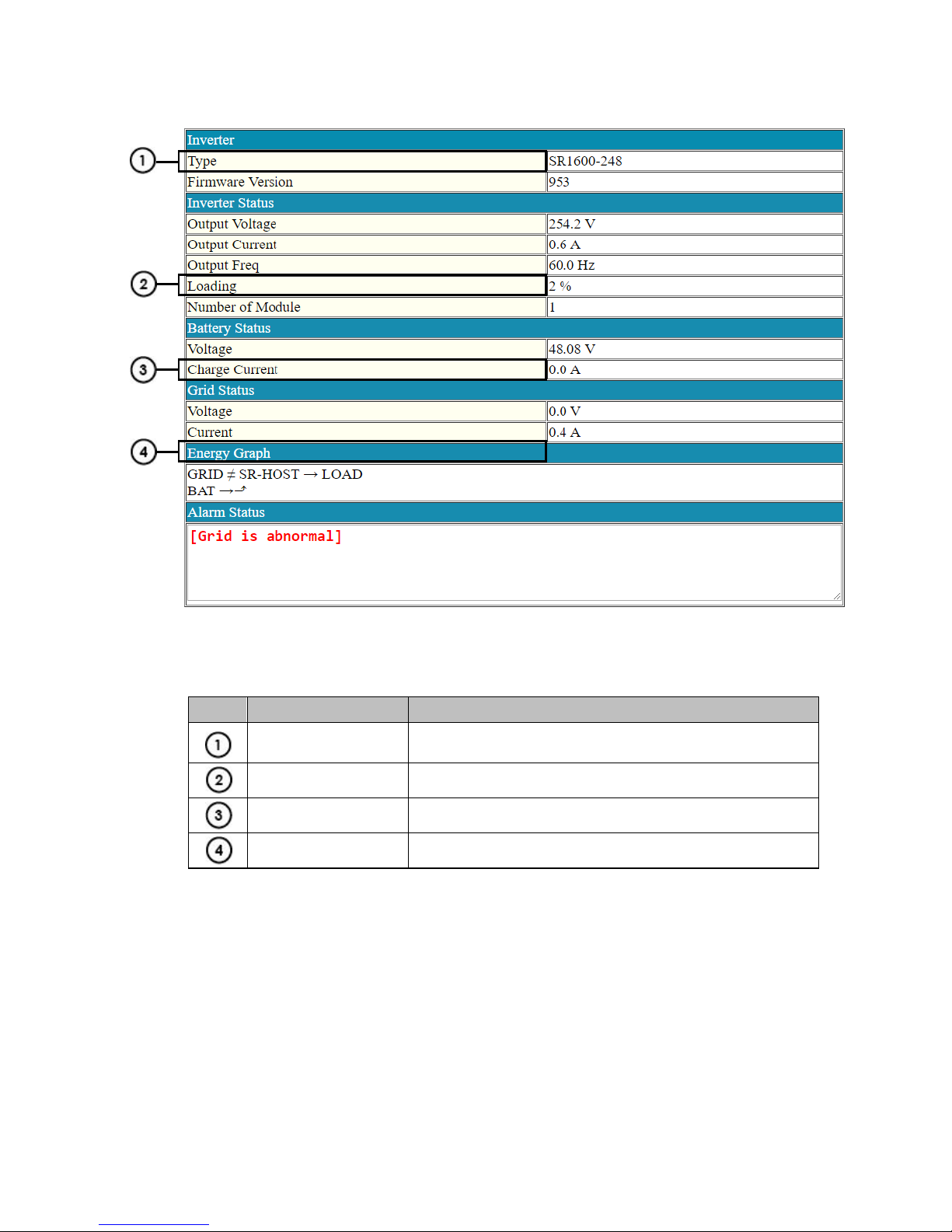
Fig. 3 Status
Description
Function
Type
Model name
Loading
Inverter loading Capacity
Charge Current
SRC Inverter series only
Energy Graph
It displays the energy stream direction
Page 6
4
1-3-3 System Control Page
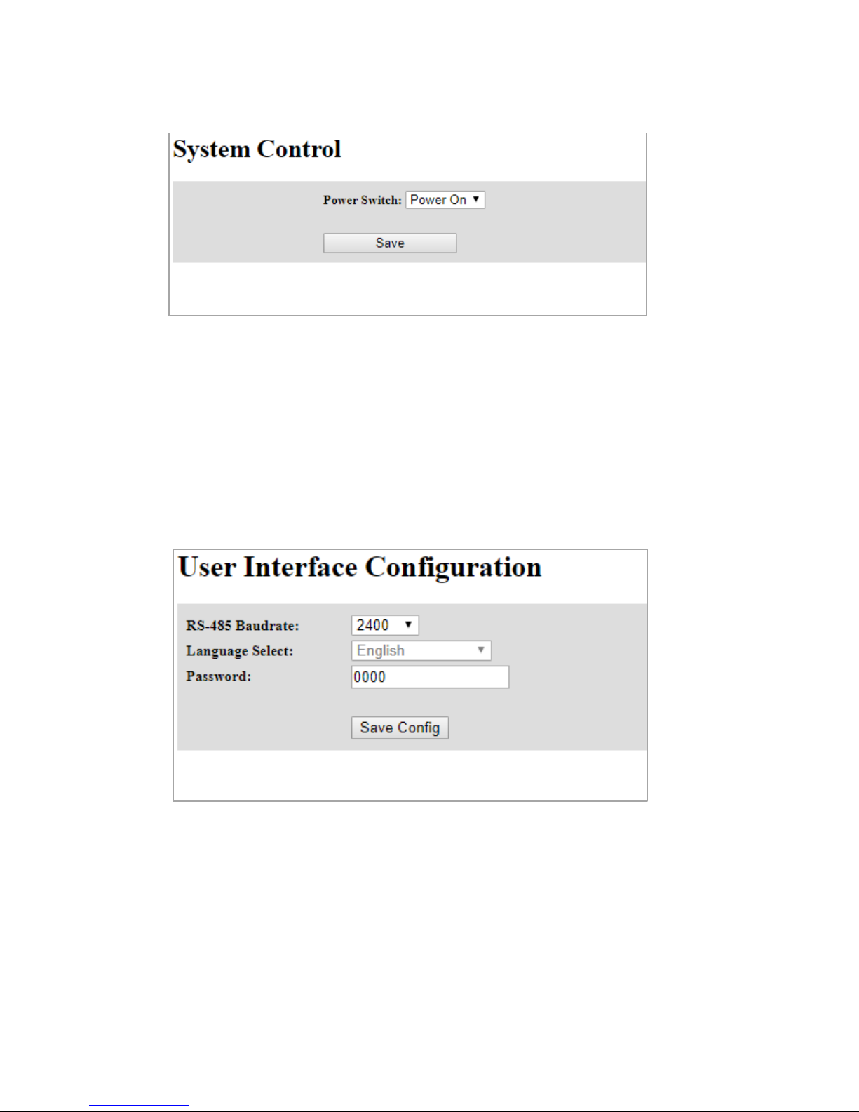
Fig. 4 System Control
Power Switch: To control the power on/off of the Inverter.
1-3-4 UI Config Page
Fig. 5 UI Config
RS-485 Baudrate: To set RS-485 baudrate.
Password: 4 digits or characters password. (Default: 0000)
Page 7
5
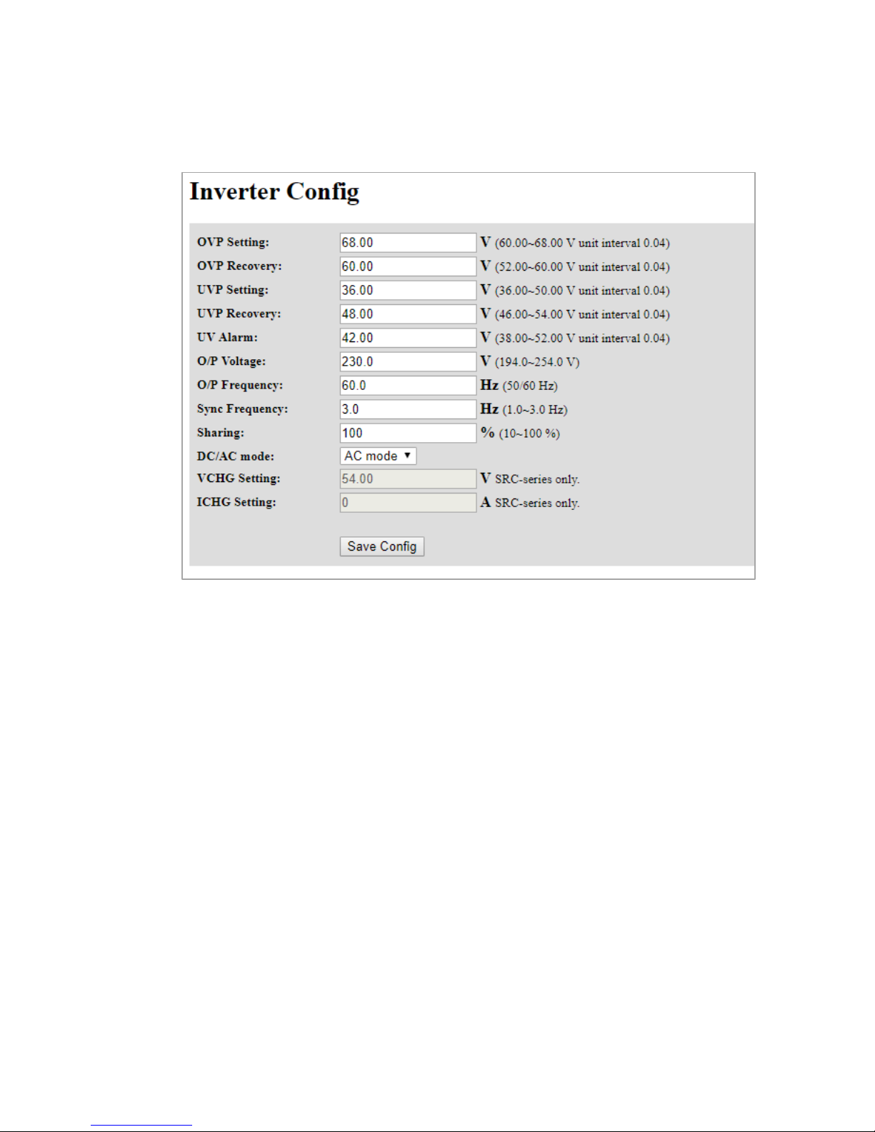
1-3-5 Inverter Config Page
Fig. 6 Inverter Config
You may change SR Host operation and protection setting in this page:
OVP Setting: Over Voltage Protection setting.
OVP Recovery: Over Voltage Protection Recovery setting.
UVP setting: Under Voltage Protection setting.
UVP Recovery: Under Voltage Protection Recovery
UV Alarm: Under Voltage Alarm.
O/P Voltage: Output Voltage setting.
O/P Current: Output Current setting.
Sync Frequency: Synchronize Frequency.
Sharing: AC input power ratio.
DC/AC mode: To set the power source priority from AC grid or battery.
VCHG: Battery charge voltage setting. * SRC Inverter series only
ICHG: Battery charge current setting. * SRC Inverter series only
Page 8
6
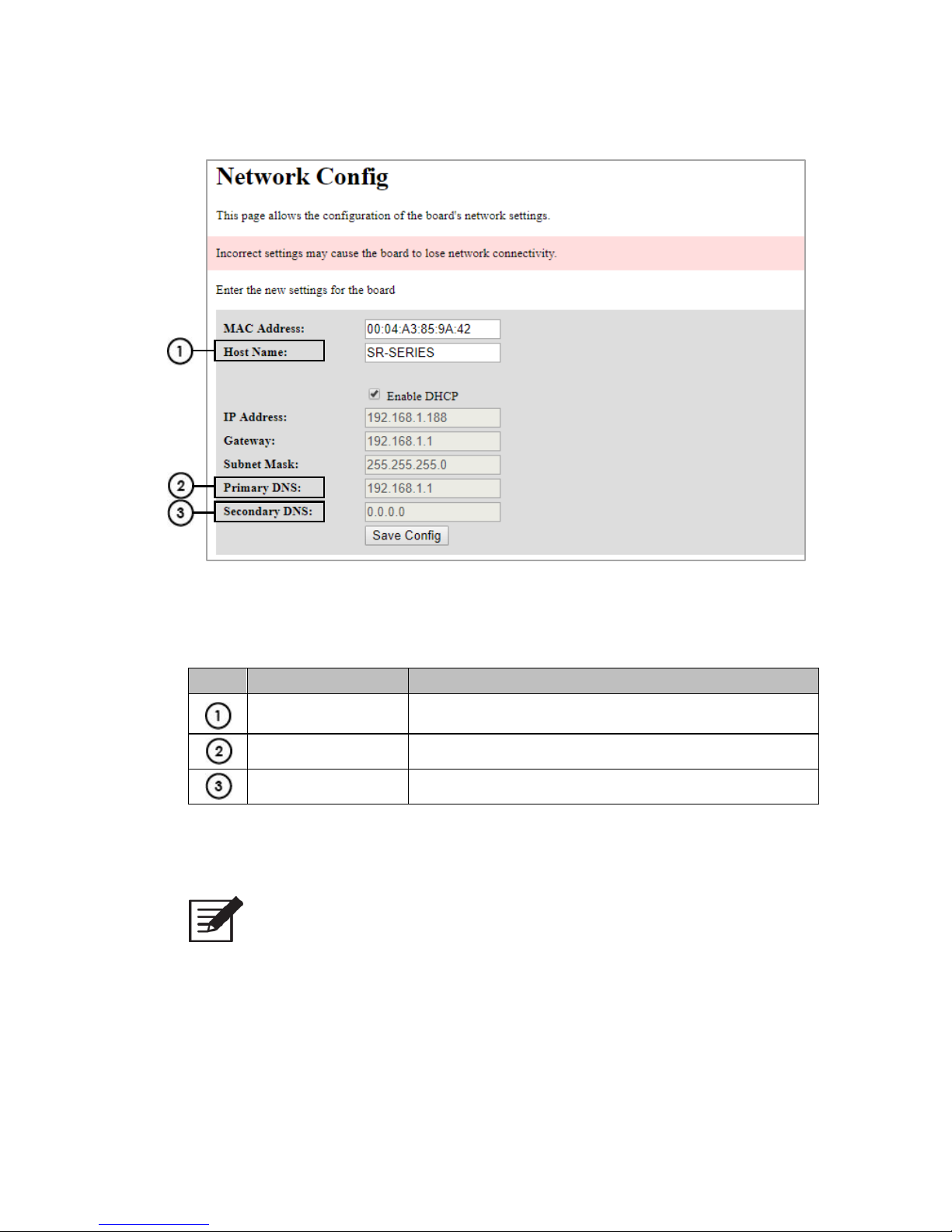
1-3-6 Network Config Page
Fig. 7 Network Config
Description
Function
Host Name
SN-1 Network Name
Primary DNS
Primary Domain Name Server
Secondary DNS
Secondary Domain Name Server
Note! Incorrect network setting may cause SN-1 connection issue.
Please set the values back to default whenever issue arises
( Refer to 2-3 )
Page 9
7
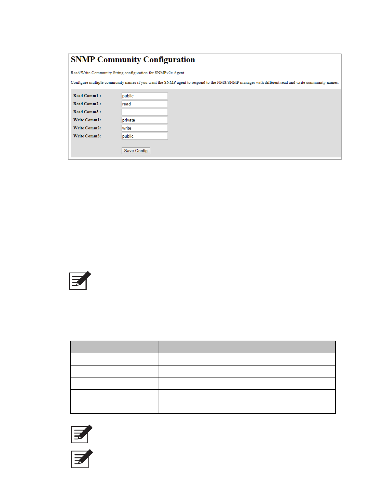
1-3-7 SNMP Config Page
Fig. 8 SNMP Config
Set SN-1 Community Name :
Read Comm1: Read Community Name 1.
Read Comm2: Read Community Name 2.
Read Comm3: Read Community Name 3.
Write Comm1: Write Community Name 1.
Write Comm2: Write Community Name 2.
Write Comm3: Write Community Name 3.
Note! After AC restart, Community Name will go back to default.
1-4. SNMP V2C Description
SNMP Agent Trap
Item
Description
trapReceiverIPAddress
NMS trap IP
trapCommunity
NMS trap community name.
trapEnable
If=0, Disable SN-1 trap , If =1, Enable SN-1 trap
trapTimeInterval
Setting the interval at which traps occur each time.
MAX = 65535 / per100ms, MIN = 1 / per100ms
Note! Please contact your COTEK local distributor for MIB file.
Note! After AC restart, trap will go back to default
Page 10
8
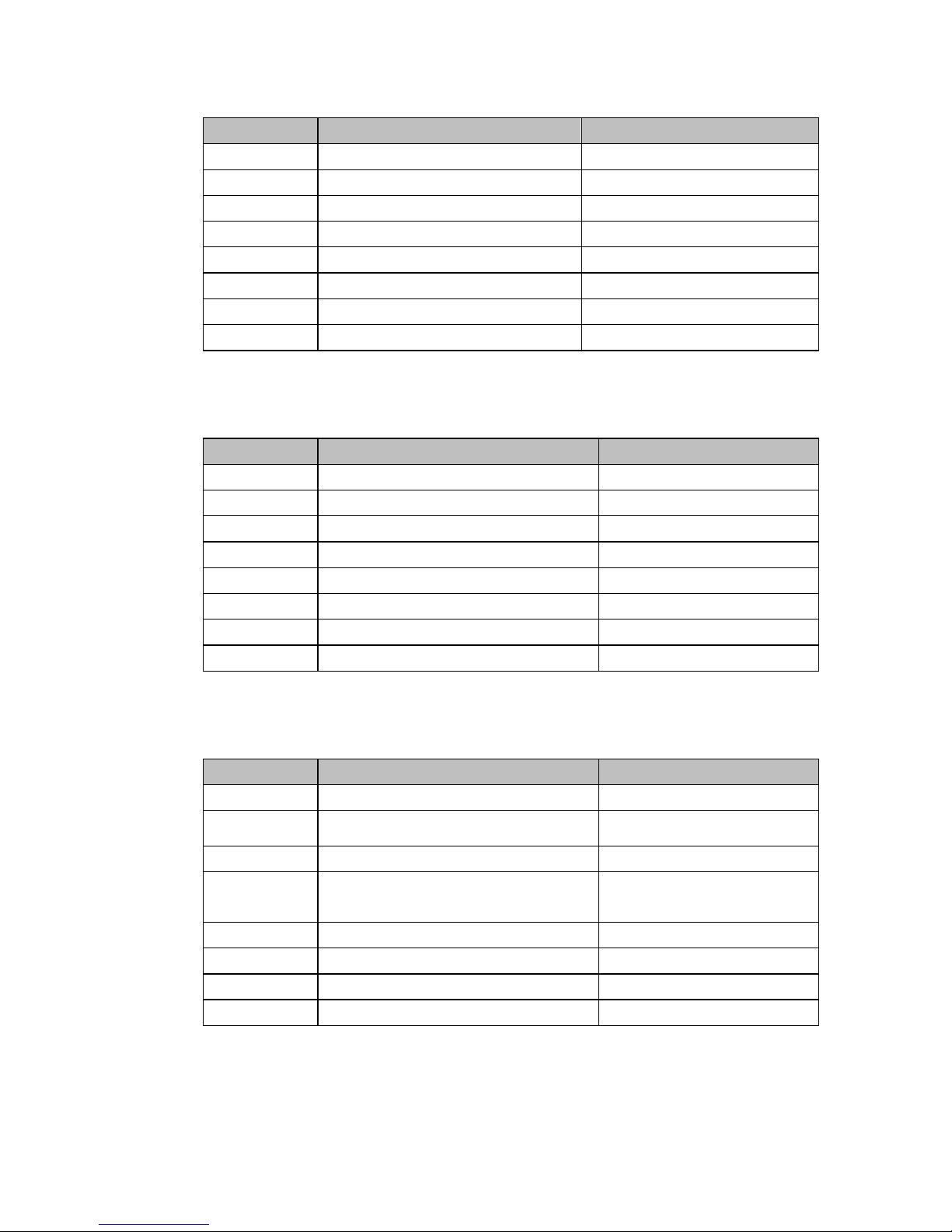
Inverter-Status1
Bit Number
Description
Value Description
Bit 0
Low Battery Alarm
=0, No =1, Yes
Bit 1
Over Load Shutdown
=0, No =1, Yes
Bit 2
Over Load Alarm
=0, No =1, Yes
Bit 3
FAN Fault
=0, No =1, Yes
Bit 4
Temperature status
=0, Normal =1, Abnormal
Bit 5
Low Battery Voltage
=0, No =1, Yes
Bit 6
High Battery Voltage
=0, No =1, Yes
Bit 7
Machine Is Running
=0, Yes =1, No
Table 3 .Inverter-Status1
Inverter-Status2
Bit Number
Description
Value Description
Bit 0
Under Battery Voltage Protection
=0, No =1, Yes
Bit 1
Over Battery Voltage Protection
=0, No =1, Yes
Bit 2
Over Load Protection
=0, No =1, Yes
Bit 3
N/A
N/A
Bit 4
Over Temperature Protection
=0, No =1, Yes
Bit 5
Under Battery Voltage Alarm
=0, No =1, Yes
Bit 6
Over Battery Voltage Alarm
=0, No =1, Yes
Bit 7
Over Load Alarm
=0, No =1, Yes
Table 4 .Inverter-Status2
Inverter-Status3
Bit Number
Description
Value Description
Bit 0
N/A
N/A
Bit 1
Grid Voltage status
=0, Abnormal. =1, Normal
Bit 2
Inverter status
=0, Normal. =1, Abnormal
Bit 3
Software Reset
=0, Normal. =1, Software
Reset
Bit 4
Operating Voltage status
=0, Normal. =1, Abnormal
Bit 5
N/A
N/A
Bit 6
N/A
N/A
Bit 7
Locked Grid Frequency / Phase
=0, Abnormal. =1, Normal
Table 5. Inverter-Status3
Page 11
9
2. Installation and Operation
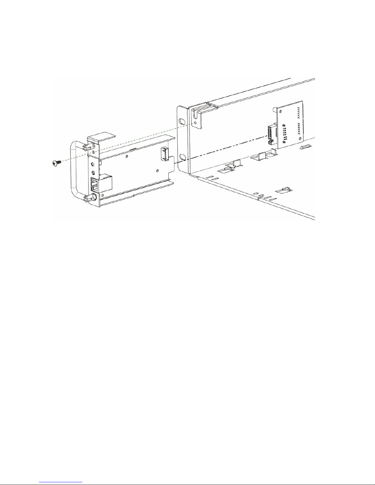
2-1 Installation of SN-1
Fig.9 Installation
Step 1 : Hold the button on the panel and slot in the SN-1 card for 1 second
Step 2 : Fix the screw
2-2 Connection from SN-1 to PC
2-2-1 Connection via the router
Connect SN-1 to the router
Find the IP address of SN-1 from the router
Type IP address of SN-1 in the web browser/NMS and then
connect to web-server/SNMP agent
Page 12
10
2-2-2 Connection via PC
Connect from SN-1 to PC
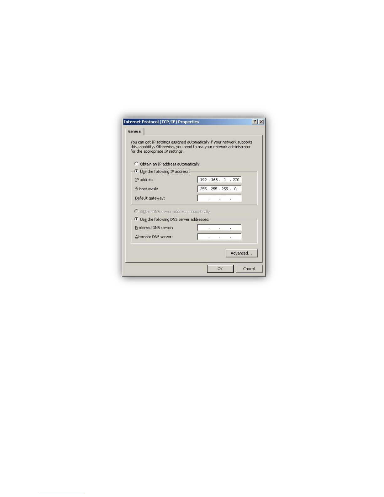
The default static IP of SN-1 is 192.168.1.250. Please change the
setting value of network interface card in PC. The static IP address of
PC is 192.168.1.X (The value X cannot be the same value of SN-1 IP’s 250)
Fig. 10 IP Setting
Type IP address of SN-1 in the web browser/NMS and then
connect to web-server/SNMP agent
2-3 Reset SN-1 to Default
Hold the button on the panel and slot in the SN-1 card for 1 second
Page 13

11
3 Troubleshooting
LED Status
Signal Description
Suggestion actions
LED Red
SN-1 fails to communicate
with SR-Host.
1. Check LED of SR-1600 module
2. Unplug and plug in SN-1 module again.
3. Check the LED status on SN-1.
LED Green
SN-1 communicates with
SR-Host correctly, but the
data transmission is still
abnormal
1. Press Reset button and go back to
default value.
2. Check if router or PC network setting is
correct.
3. Check firewall setting and PORT
80,161,162 for SN-1
4. Change another Ethernet cable.
Table 6. Troubleshooting guide
4 Warranty
We guarantee this product against defects in materials and workmanship for a period
of 24 months from the date of purchase. In case you need to repair or replace any
defective power inverters, please contact COTEK local distributor.
This warranty will be considered void if the unit has been misused, altered, or
accidentally damaged. COTEK is not liable for anything that occurs as a result of the
user’s fault.
Page 14

No.33, Sec. 2, Renhe Rd., DaxiDist., Taoyuan City 33548, Taiwan
Phone:+886-3-3891999 FAX:+886-3-3802333
http:// www.cotek.com.tw
2017.11._A0
 Loading...