

Page 1
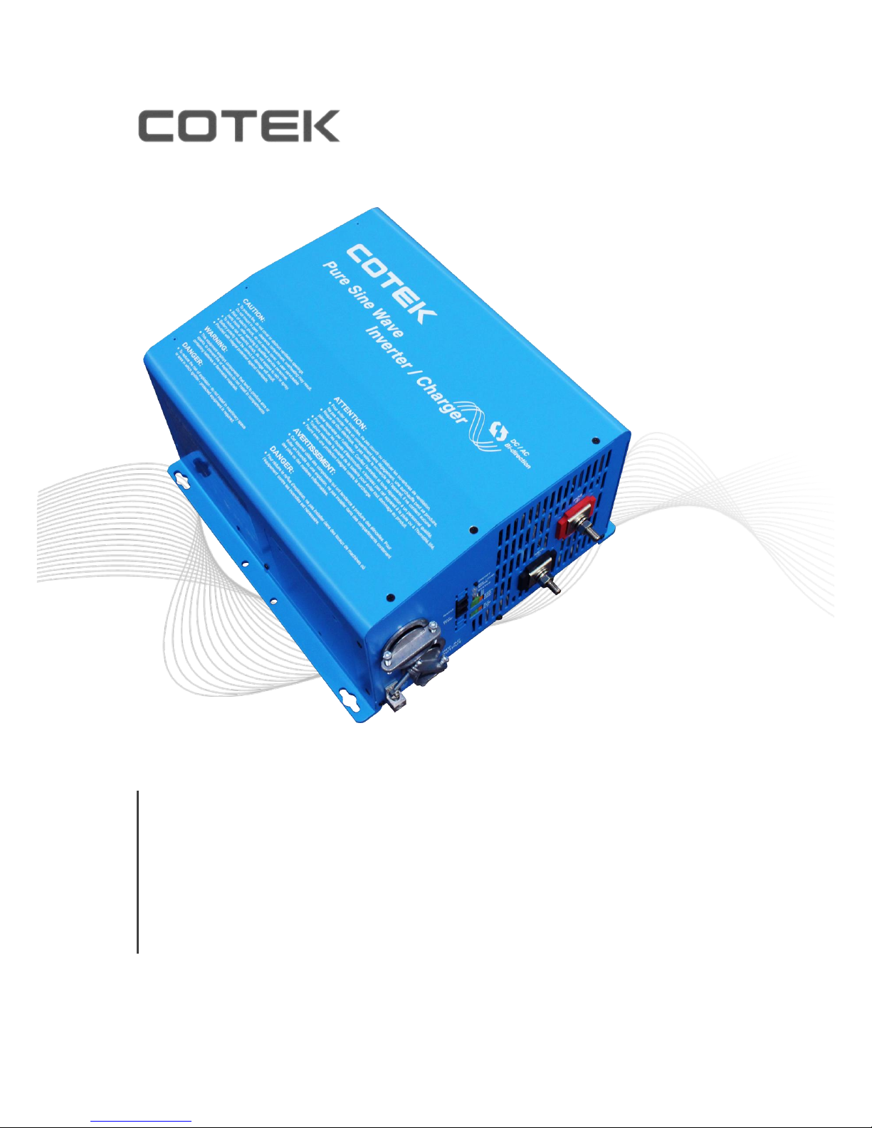
PURE SINE WAVE INVERTER CHARGER
WITH SUPPORT / SHARING / GENERATOR
SL Series User’s Manual
SL-2000 / SL-3000
Page 2

Page 3

Legal Provisions
Copyrights 2017 COTEK Electronic IND. CO. All Rights Reserved.
Any part of this document may not be reproduced in any form for any purpose without the prior written
permission of COTEK Electronic IND. CO. For the conditions of the permission to use this manual for
publication, contact COTEK Electronic IND. CO., LTD. In all related COTEK product activities, Neither
COTEK Electronic IND. CO., LTD. nor its distributors or dealers be liable to anyone for indirect, incidental, or
consequential damages under any circumstances. Specifications are subject to change without notice. Every
attempt has been made to make this document complete, accurate and up-to-date. COTEK Electronic IND.
CO., LTD reserve the right to make changes without notice and shall not be responsible for any damages,
including indirect, incidental or consequential damages, caused by reliance on the material presented,
including, but not limited to, omissions, typographical errors, arithmetical errors or listing errors in the content
material. All trademarks are recognized even if these are not marked separately. Missing designations do not
mean that a product or brand is not a registered trademark.
Page 4

Table of Content
1. SAFETY INTRODUCTIONS 1
1-1. General Safety Precautions 1
1-2. Personal Precautions 1
1-3. Other Safety Notes 3
2. FUNCTION CHARACTERISTICS INTRODUCTION 4
2-1. System Overview 4
2-2. Electrical Specification 5
2-3. Mechanical Drawings 6
3. INSTALLATION AND MAINTENANCE 7
3-1. Unpacking the product 7
3-2. Front Panel Introduction 7
3-3. AC Wiring Installation 9
3-4. Mounting Instruction 11
3-5. Battery Bank Configuration 12
4. SYSTEM FUNCTION INTRODUCTION 13
4-1. Battery Charger Introduction 13
4-2. Operation Mode Introduction 16
5. TROUBLESHOOTING 20
6. WARRANTY 20
Page 5

1
1. Safety Introductions
1-1. General Safety Precautions
This manual contains important safety and operating instructions SL series.
WARNING
To reduce risk of injury, charge only Lead-acid type rechargeable batteries. Other types of batteries
may burst causing personal injury and damage.
Do not expose the inverter to rain, snow, spray or dust. To reduce the risk of fire hazard, do not cover or
obstruct the ventilation openings and do not install the inverter in a zero-clearance compartment.
To avoid the risk of fire and electric shock, make sure that the existing wiring is in good electrical condition,
and the wire size is not undersized.
To reduce risk of electric shock, unplug power unit from outlet before attempting any maintenance or
cleaning. Turning off controls will not reduce this risk.
This equipment contains components which can produce arcs or sparks. To prevent fire or explosion do
not install in compartment containing batteries or flammable materials or in location which require ignition
protected equipment. This includes any space containing gasoline-powered machinery, fuel tanks, or joints,
fittings, or other connection between components of the fuel system.
Depending on the user scenario, the AC output of the inverter may require user installed breaker or fuse.
In AC output hardwire application, AC socket will not been provided. The inverter incorporates standard
AC short circuit protection.
An over current protection at the time of installation shall be provided by others for the AC output circuit.
1-2. Personal Precautions
i) Someone should be within range of your voice or close enough to come to your aid when you work near
a lead-acid battery.
ii) Have plenty of fresh water and soap nearby in case battery acid contacts skin, clothing, or eyes.
iii) Wear complete eye protection and clothing protection. Avoid touching eyes while working near battery.
iv) If battery acid contacts skin or clothing, wash immediately with soap and water. If acid enters eye,
immediately flood eye with running cold water for at least 10 min and get medical attention immediately.
v) NEVER smoke or allow a spark or flame in vicinity of battery or engine.
vi) Be extra cautious to reduce risk of dropping a metal tool onto battery. It might spark or short-circuit
battery or other electrical part that may cause explosion.
Page 6

2
vii) Remove personal metal items such as rings, bracelets, necklaces, and watches when working with a
lead-acid battery. A lead-acid battery can produce a short-circuit current high enough to weld a ring or the
like to metal, causing a severe burn.
viii) NEVER charge a frozen battery.
ix) If necessary to remove battery from vessel, always remove grounded terminal from battery first. Make
sure all accessories in the vessels are off, so as not to cause an arc.
x) Be sure area around battery is well ventilated.
xi) Clean battery terminals. Be careful to keep corrosion from coming in contact with eyes.
xii) Study all battery manufacturer’s specific precautions such as removing or not removing cell caps while
charging and recommended rates of charge.
xiii) Add distilled water in each cell until battery acid reaches level specified by battery manufacturer. This
helps purge excessive gas from cells. Do not overfill. For a battery without cell caps, carefully follow
manufacturer’s recharging instructions.
1-3. Other Safety Notes
DC CONNECTION PRECAUTIONS
Connect and disconnect DC output connections only after setting the power unit switches to off position
and removing AC cord from electric outlet or opening AC disconnect.
GROUNDING INSTRUCTIONS – This power unit should be connected to a grounded, metal, permanent
wiring system; or an equipment-grounding conductor should be run with circuit conductors and connected
to equipment-grounding terminal or lead on unit. Connections to unit should comply with all local codes
and ordinances.
Upon receipt, examine the carton box for damage. If you have found any damage on the carton box please
notify the company you purchased this unit from.
Do not operate near water or in excessive humidity.
Do not open or disassemble the inverter, and warranty may be voided.
The DC side connections should be firm and tight.
Install the inverter in a well-ventilated area. Do not block the front air vents, or the rear air exhausts of the
unit.
Wiring: Adequate input power must be supplied to the inverter for proper use; correct wiring sizes must be
ensured.
Do not operate appliances that may feed power back into the inverter.
Temperature: The inverter should be operated in an ambient temperature range of -20℃ to 40℃ otherwise
the output efficiency may be affected. Air flow to the inverter must not be blocked.
Page 7

3
RECOMMEND GFCI CONNECTOR
a) HUBBELL INC WIRING DEVICE DIV, Type GFRST20. Rated 125V, 20A
b) COOPER WIRING DEVICES, Type SGF20. Rated 125V, 20A
c) Leviton Mfg. Co. Ltd, Type GFNT2. Rated 125V, 20A
WARNING REGARDING THE USE OF BATTERIES
Excessive battery discharge and / or high charging voltage can cause serious damage to batteries. Do not
exceed the recommended limits of discharge level of your batteries. Avoid short circuiting batteries, as this
may result in explosion and fire hazard. Installation of the batteries and adjustments of the unit should only
be undertaken by authorized personnel!
Page 8
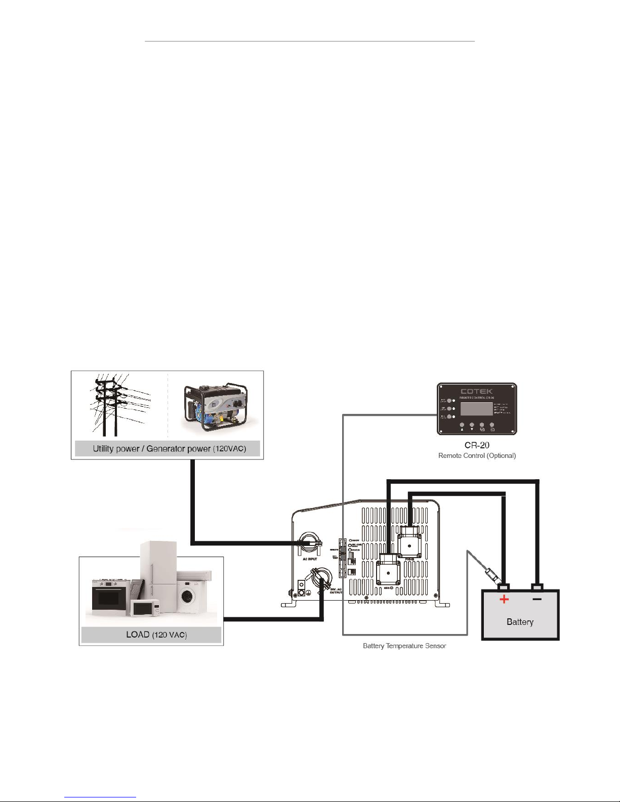
4
2. Function Characteristics Introduction
2-1. System Overview
The SL Series is an inverter / charger system, designed with advanced power electronic and microprocessor
technology offering the following features:
The unit is equipped with a self diagnosis microprocessor that is able to identify and show all failure
messages on the LED, with associated visual/audio alarms.
Battery charger current 100A max for SL-2000,125A max for SL-3000,@12VDC
Equalization charging function for the batteries.
Adjustable up to 50A @120VAC bypass function.
Power Sharing / Generator function.
RS-232 protocol communication for power management.
Fan controls by load and temperature.
Remote management and control.
Dry contact terminal for power on/off faulty signal.
Over temperature protection:Inverter / Battery / Key parts
Fig. 1:SL series System Overview
Page 9
5
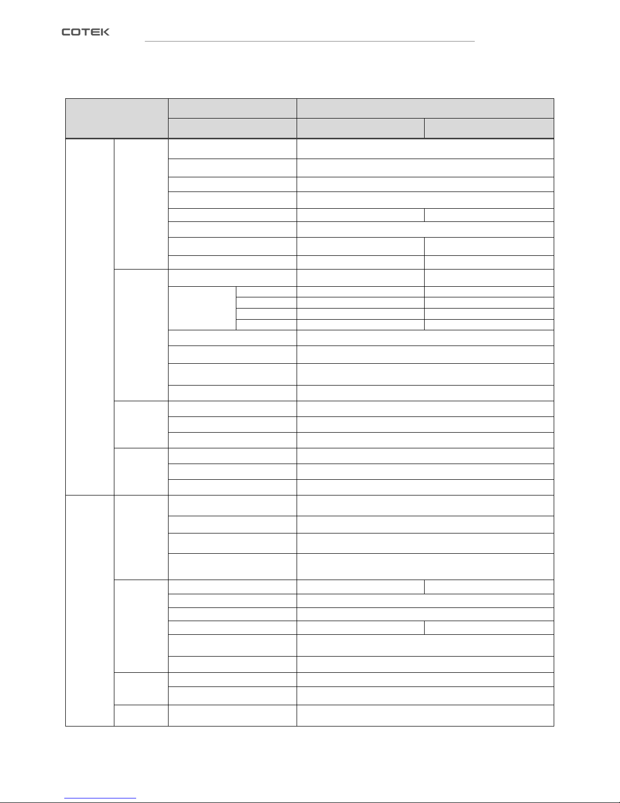
2-2. Electrical Specification
Electrical
Specification
Model No.
Item
SL-2000-112
SL-3000-112
Inverter
Mode
Input
DC Voltage
12 VDC
Input Voltage Range
9~17 VDC±0.3V
Input Over-Voltage Protection
Default 17 VDC , 16.5 ~ 17 VDC
Input Under-Voltage Protection
Default 9 VDC , 9 ~ 10.5 VDC
Max. DC input current
267A
400A
AC Relay Transfer Time
<16ms
No Load Power Consumption
25W
40W
Saving Power Consumption
< 5W
< 8W
Output
Continuous Output Power
2000 VA ± 3%
3000 VA ± 3%
Surge Power
(real watts)
<5 sec.
>3200VA, <3400VA
>4800VA, <5100VA
<30 sec.
>2900VA, <3200VA
>4350VA, <4800VA
<5 min.
>2300VA, <2900VA
>3450VA, <4350VA
<30 min.
>2000VA, <2300VA
>3000VA, <3450VA
Frequency
60 Hz ± 0.1Hz
Output Voltage
120 VAC ± 5% (≦Continuous Power)
Max. Efficiency
>90%
Output Waveform
Pure Sine Wave (THD < 5%@12.5VDC Full Load)
Signal and
Control
Remote Controller Panel Unit
CR-20 (optional)
LED Indicator
Red / Orange / Green LED
Dry Contact Terminal
By a relay
Protection
Input Protection
Over / Under Voltage, Reverse Polarity (Internal Fuse)
AC Output Protection
Short-Circuit, Overload
Others
Over / Under Temperature Protection
Charger
Mode
Charger
Battery Temperature protection
By a RJ-11 connector to battery temperature sensor
AC Input Voltage Range
80 ~ 140 VAC ± 5% (120VAC nominal)
AC Input Frequency Range
50 ~ 70 Hz
AC Input Current Range
5 ~ 50A *
Charger
AC Nominal Current
15A
18A
Charger efficiency (peak)
85%
Power Factor Correction (PFC)
> 0.97 (50% Load)
Charging Current Range
0 ~ 100A
0 ~ 125A
Battery Temperature
Compensation
25 mV per ℃
Four-stage charging
Bulk, Absorption, Final, Equalize*
Equalization
Max. output Voltage
16VDC
Max. output Current
10A
Bypass
Switch
Switch Specification
(Max. each input)
AC 50Amp
*Setting by remote control
Page 10
6
Electrical
Specification
Model No.
Item
SL-2000-112
SL-3000-112
Operating Temp.
Range
Full Load
-20 ℃ ~ 40 ℃
Power de-rating
60 W per ℃, 41~60 ℃
Storage
-30 ℃~70 ℃
Over-temperature Protection
Sensor on Transformer, MOSFETs, Battery,
and Internal ambient
Operating
Humidity Range
0~95% Non-condensing
Ground Relay
Default setting is closed. User may Neutral to ground at inveter mode ifnecessary, as ground relay
is included in SL series.
Mechanical
Specification
Dimension (W x H x D)
321X203X349mm / 12.64x7.99x13.74 inch
Net Weight
17.6 Kg (38.71 Lbs)
22.6 Kg (49.82 Lbs)
Safety and EMS
Safety Standards
UL458 for Vehicle & Marine ,
Supplement SA / CSA C22.2 No. 107.1-01
EMC Standards
FCC Class B
EN55022:1998+A1:2000+A2:2003 Class B
EN55024:1997+A1:2001+A2:2003
EN61000-3-2:2006 Class A
EN61000-3-3:1995+A1:2001
Table 1:SL-2000 / 3000 Specification
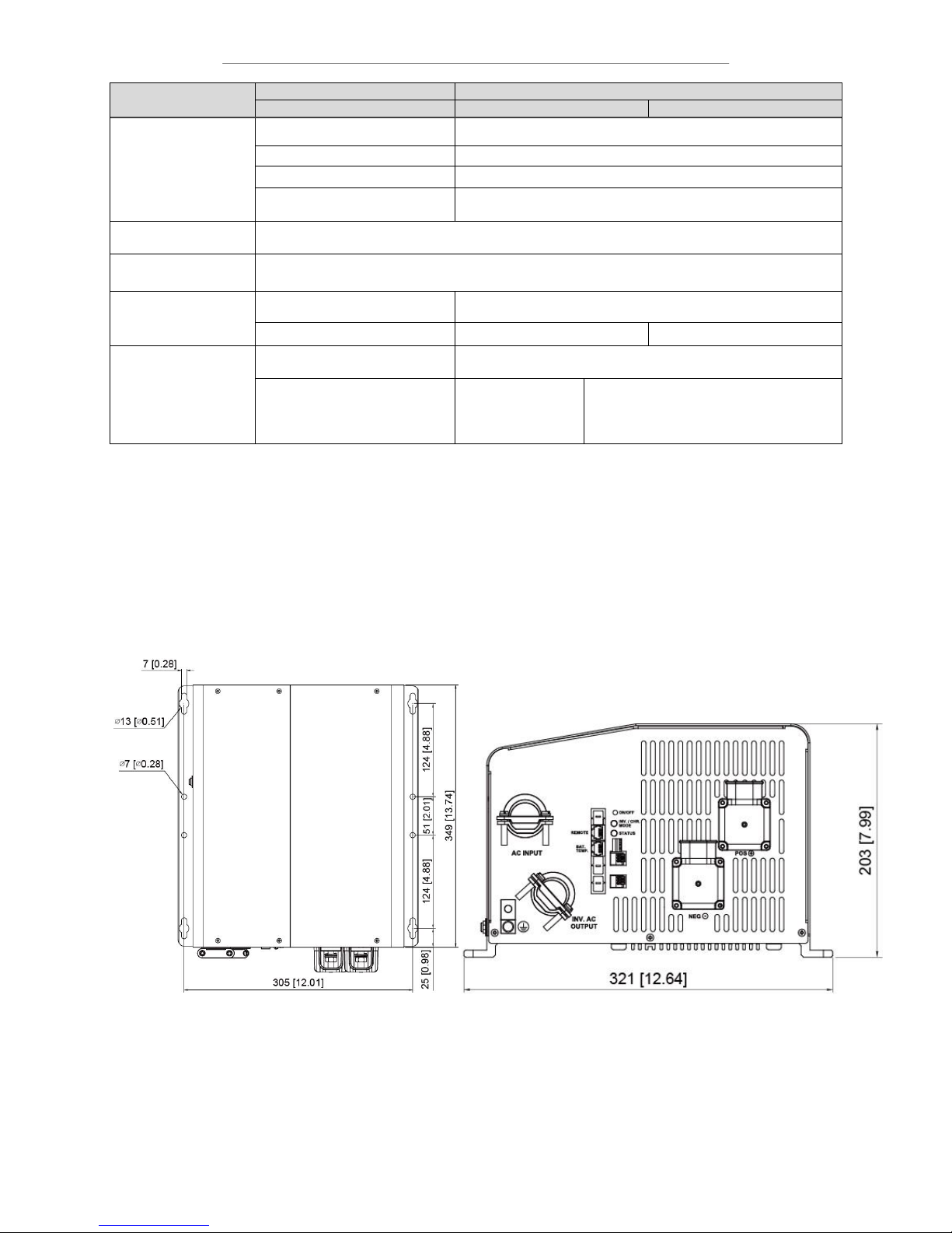
1-3. Mechanical Drawings (Unit:mm [inch])
Fig. 2:SL series mechanical drawings
Page 11
7
3. Installation and Maintenance
3-1. Unpacking the product
The package of SL inverter charger includes:
SL inverter charger
Battery temperature sensor
DC Terminal cover ( Red / Black)
Screw x 8 pcs
Ring Lug x 2 pcs
Quick Guide Instruction
After unpacking, check the contents for possible damage. Do not use the product if it is damaged. In case of the
contents damaged, please contact your supplier.
Check from the identification label whether the battery voltage is the same as the DC-input voltage of the unit
(e.g. 12V battery set for a 12V input voltage). Also check that the AC output voltage and output power of the unit
satisfies loading requirements.
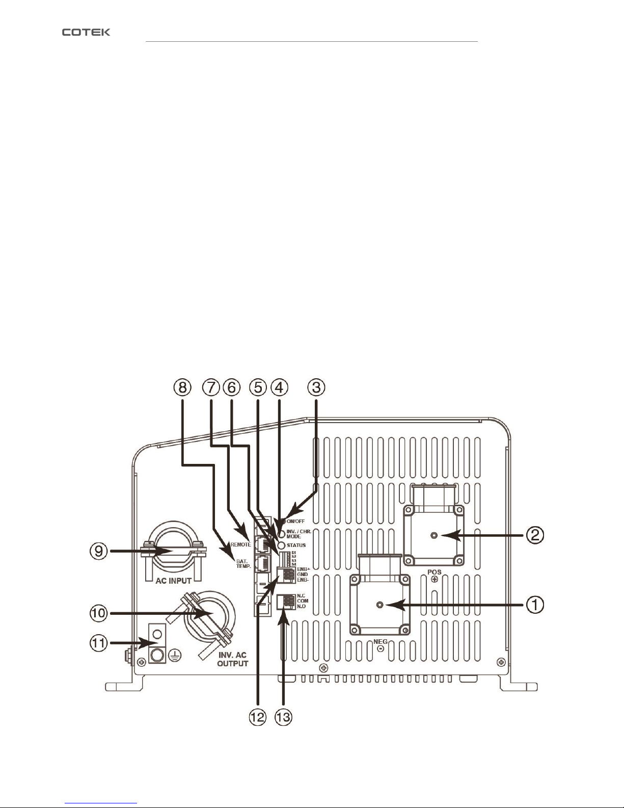
3-2. Front Panel Introduction
Fig. 3:SL series front panel introduction
Page 12
8
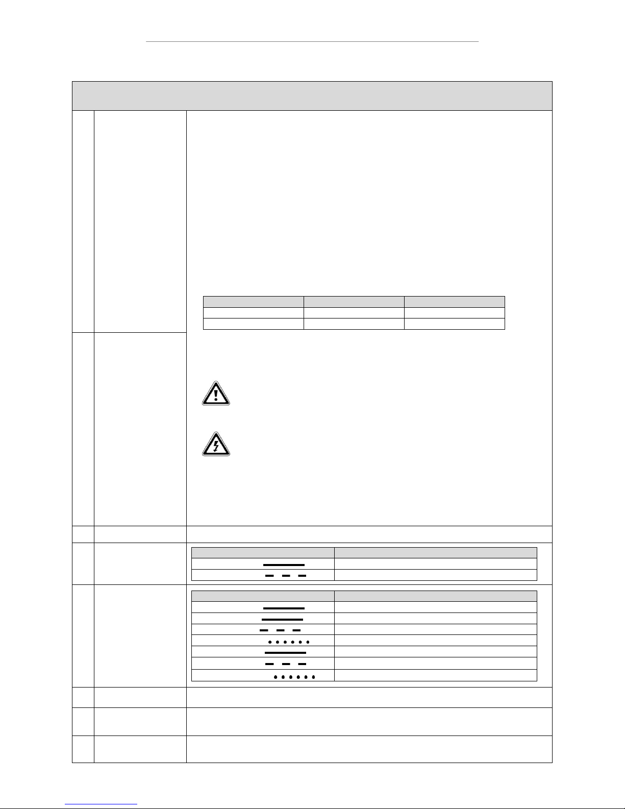
Front panel
①
DC Input Connection(-)
Follow the instructions to connect the battery cables to the DC input terminals of the unit. The cables
should be as short as possible (less than 6 feet / 1.8 meters ideally) so that they can handle the required
current in accordance with the Electrical Codes and Regulations. The size of the cable should be thick
enough to limit the voltage drop to less than 2% when carrying the maximum input current to prevent
frequent low-input voltage warnings, and shutdown. UVP (Under Voltage Protection) warning may result
if there is excessive voltage drop across the DC cables between the batteries and the unit. Increasing
your DC cable size will help improve the situation.
Batteries are capable of providing very large currents in case of short circuit. In case there is a short
circuit in the cable run between the batteries and the input terminals of the unit, it will result in
overheating / melting of the cables and consequent risk of fire and injury, to prevent possibility of this
hazard, use Very Fast Acting DC Fuse in line with the positive cable. The fuse should be as close to the
positive battery terminal as possible.
The following sizes of cables and fuses are recommended for up to 6 ft. distance between the batteries
and the unit. (Applies to both 120 VAC and 240 VAC versions):
Model No.
Wire AWG
Inline Fuse
SL2000-112
# 2 / 0
400 A
SL3000-112
#4 / 0
700A
Connect DC input terminals to 12V battery or other DC power source.
[ + ] is positive, [ - ] is negative. Reverse polarity connection can blow the internal fuse and may damage
the unit.
WARNING!
Make sure that all the DC connections are tight (torque to 9 – 10 ft-lbs, 11.7 - 13 Nm).
Loose connections could result in overheating and can be a potential hazard.
CAUTION
The recommended inline fuse should be installed as close to the battery positive terminal
as possible failure to use a fuse on the “+” cable running between the unit and battery may
cause damage to the cable / unit.
Also, only use high quality copper wire and keep the cable length short which is as maximum of 3 – 6
feet.
②
DC Input Connection(+)
③
Power Switch
A momentary push-button switch that alternately turns the inverter On / Off.
④
INV./CHR. Mode LED
Indicator
LED status
Status
Solid Green
Inverting Mode
Blink Green
Charging Mode
⑤
STATUS LED Indicator
LED status
Status
Solid Green
Normal
Solid Red
Power off
Red Blink
Over Voltage Protection (Input DC voltage over spec.)
Red Fast Blink
Under Voltage Protection (Input DC voltage under spec.)
Orange solid
Over Load Protect / Short-circuit Protection
Orange Blink
Over Temperature Protection
Orange Fast Blink
Under Temperature Protection
⑥
DIP Switch
Factory Setting only
⑦
RS-232 / Remote
control port
RS-232 Port:Serial port monitoring and control through computer interface.
Remo control port:connector to CR-20.
⑧
Battery Temperature
Sensor port
The unit is delivered with a battery temperature sensor. When the battery temperature is high, the charge
voltage is automatically decreased.
Page 13
9
Table 2:SL series front panel introduction
WARNING!
An inverter warning label should be installed in a visible location on the breaker panel that is being
powered by the SL2000/3000. This label should state that that the panel may still be "LIVE" after
grid AC power is turned off, To ensure that no power is present or feeding when the inverter
switches off.
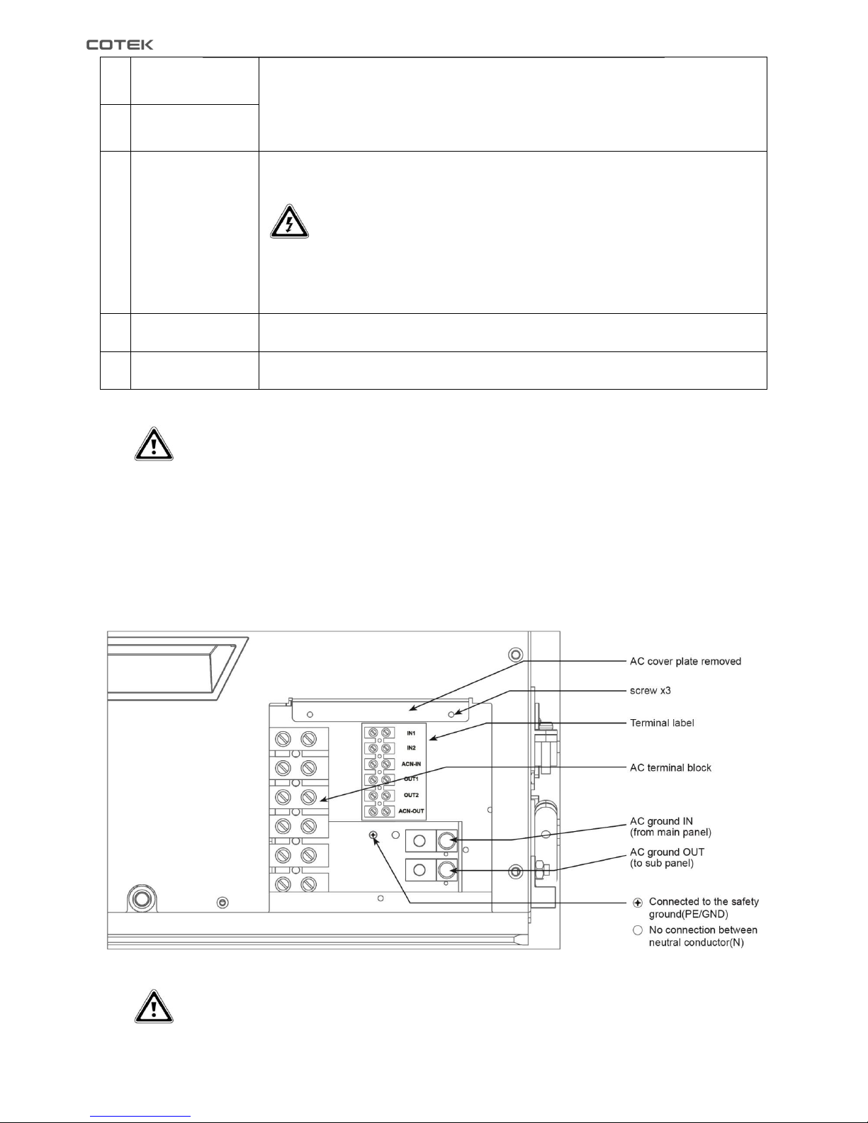
3-3. AC wiring installation
3-3-1. AC Terminal Block Connections
Fig. 4:AC terminal block connections
WARNING!
The AC neutral should be only be connected to one safety ground at a time. If more than one
connection between the neutral and ground is made, the current circulation could cause ground
loops, trip GCFI and then cause electric shock hazard.
⑨
AC Input Connections
Two 1 inch knockouts provided with cable-clamp strain reliefs to allow and hold the AC input and output
field wiring.
⑩
AC Output Connections
⑪
Chassis Ground
This connection is used to tie the exposed chassis of the inverter to the DC grounding system. This
terminal accepts CU/AL conductors from #14 to #2 AWG (2.1 to 33.6 mm2).
WARNING!
The ground wire offers protection only if the cabinet of the unit is connected to the safety
ground. Connect the chassis ground terminal to the hull or the chassis. Refer to local
regulations on grounding connection!
⑫
Remote control green
terminal
Use 20 ~ 24 #AWG wire to connect the remote control terminals.
⑬
Dry Contact Green
Terminal
Dry contact terminals can be connected to a Form C relay for “FAULT” indication.
Page 14
10
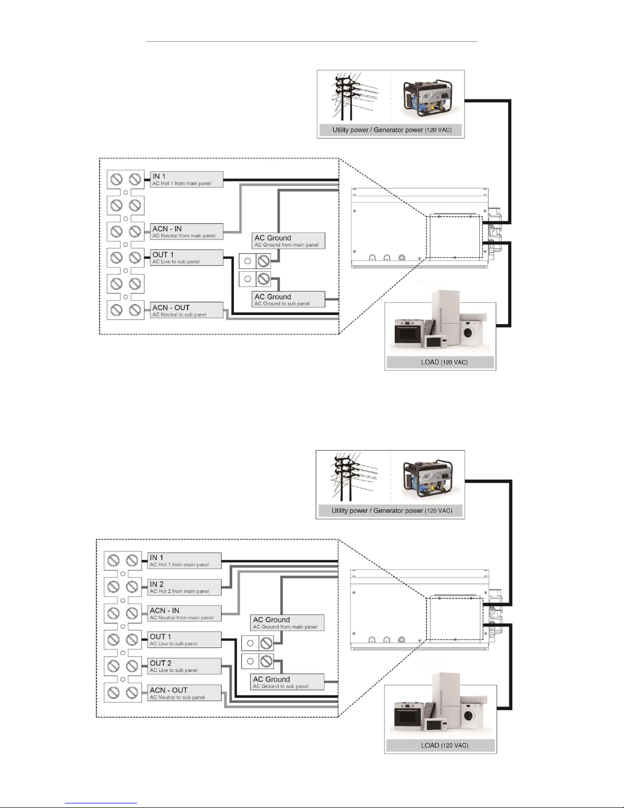
3-3-2. Single Phase, Single IN / Single OUT
Fig. 5
:
AC Wiring – Single Phase, Single IN / Single OUT
3-3-2. Split Phase, Dual IN / Dual OUT
Fig. 6
:
AC Wiring – Split Phase, Dual IN / Dual OUT
Page 15
11
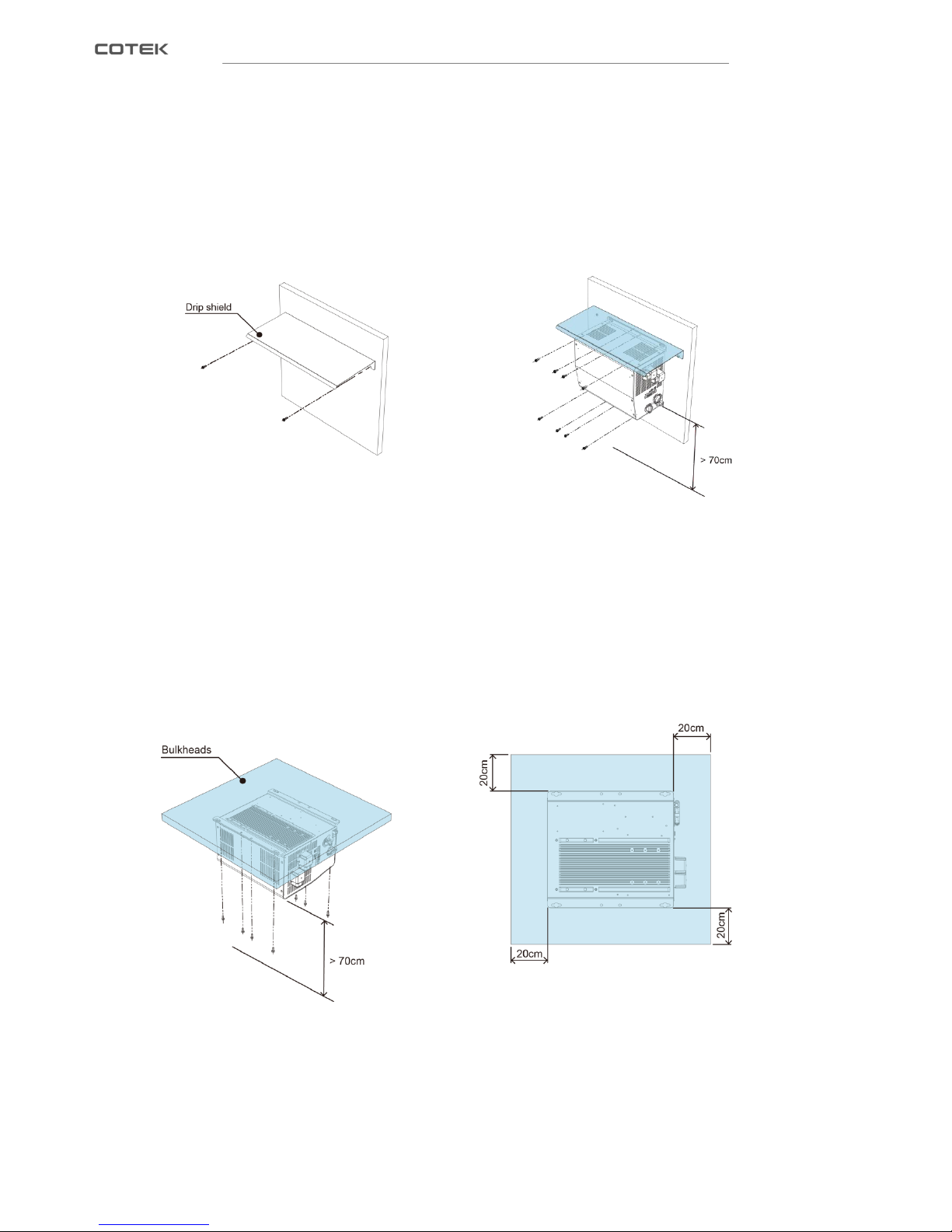
3-4. Mounting Instruction
3-4-1. Wall Mount ( For Marine )
Step 1. Use the screws to mount the Drip shield on the wall.
Step 2. Use the screws to mount the product under the Drip shield. Please make sure the height from the
ground to product at least 70 cm.
Fig. 7:Wall mount step 1 Fig. 8:Wall mount step 2
3-4-2. Ceiling Mount ( For Vehicle and Marine )
Use the screws to mount the product on the wall, and the product mounting requirement is as follow:
a. The mounting height from the ground to product requires at least 70 cm.
b. The bulkhead size requires at least 20 cm clearance each side of the inverter.
Fig. 9
:
Ceiling mount
Page 16
12
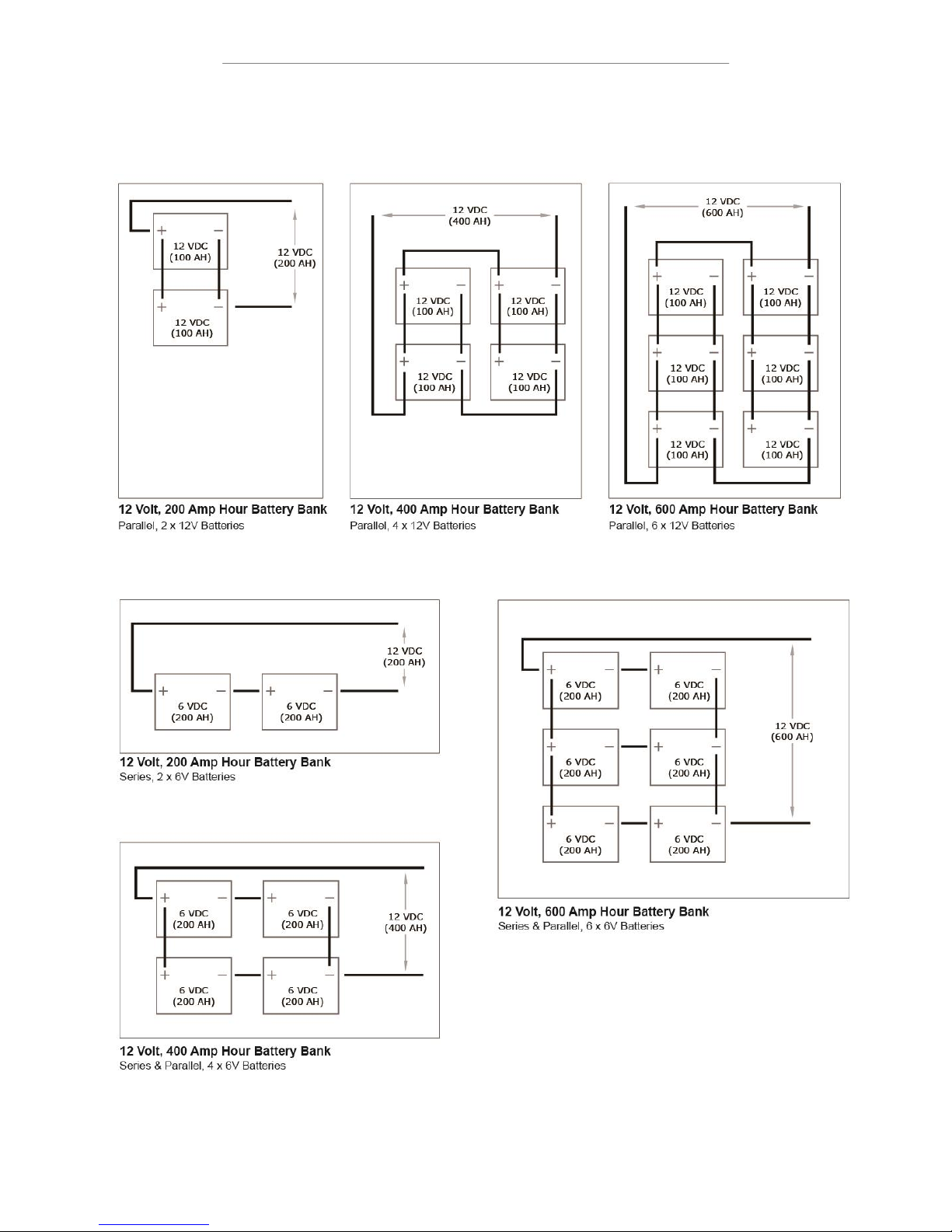
3-5. Battery Bank Configuration
Page 17
13
4. System Function Introduction
SL series is a battery charger, a pure sine wave inverter and an AC transfer system in one compact enclosure. The
three-step charging function guarantees that the batteries are always charged 100%. The pure sine wave inverter
assures that the AC output voltage is perfectly reliable even when limited external AC power is available. External
AC power can be supplied by a public grid or a generator. DC power can be delivered by charged batteries.
4-1. Battery Charger Introduction
SL series can connect many types of battery (default setting is Gel), and user can adjust the parameters by
remote control or RS-232 to meet battery charging characteristics.
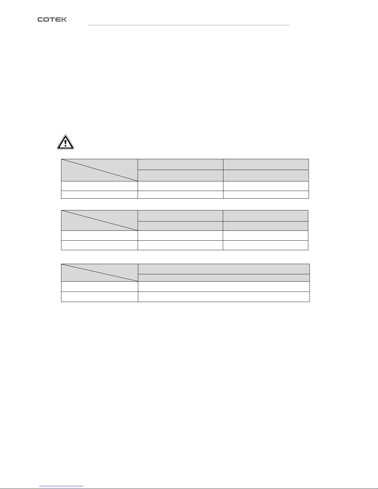
The following table shows some battery type charging setting as example.
CAUTION
Safety instruction: The setting for traction battery should never be used with a battery bank that
consists of 2V GEL cells.
Battery Type
Stage
Gel
Flooded
@12VDC
@12VDC
Absorption Voltage
14.1VDC
14.6VDC
Float Voltage
13.6VDC
13.4VDC
Table 2:Battery type charging setting I
Battery Type
Stage
AGM 1
AGM 2
@12VDC
@12VDC
Absorption Voltage
14.3VDC
14.5VDC
Float Voltage
13.1VDC
13.5VDC
Table 3:Battery type charging setting II
Battery Type
Stage
Custom
@12VDC
Absorption Voltage
12~16VDC
Float Voltage
12~16VDC
Table 3:Battery type charging setting III
Page 18
14
4-1-1. Battery Charging Function Description
SL series is equipped with a PFC (Power Factor Corrected) and PI (Proportional-Integral) multistage battery
charger. The PFC feature controls the amount of power used to charge the batteries to obtain a power factor as
close as possible to 1 (or unity).. The PI feature allows the charger voltage and current to change independently.
These two features maximize the real power available from the AC power source (i.e., utility or generator),
which leads to less power wasted and greater charging capabilities than most chargers today. When an AC
source is connected to the AC input, the inverter begins monitoring AC voltage. Once the AC voltage is
accepted, charge mode begins. After the charge mode begins, the inverter’s battery voltage is monitored to
determine the charging stage. If the battery voltage is low (≤12.8 VDC/12-volt), the charger begins Bulk
charging. If the DC voltage is high (>12.8 VDC/12-volt), the charger will skip Bulk and Absorb stages and go
directly to Final charging. However, if the incoming AC power is lost and returns within 2 minutes the charge
mode returns to the charge stage it was in prior to losing AC input—regardless of the battery voltage.
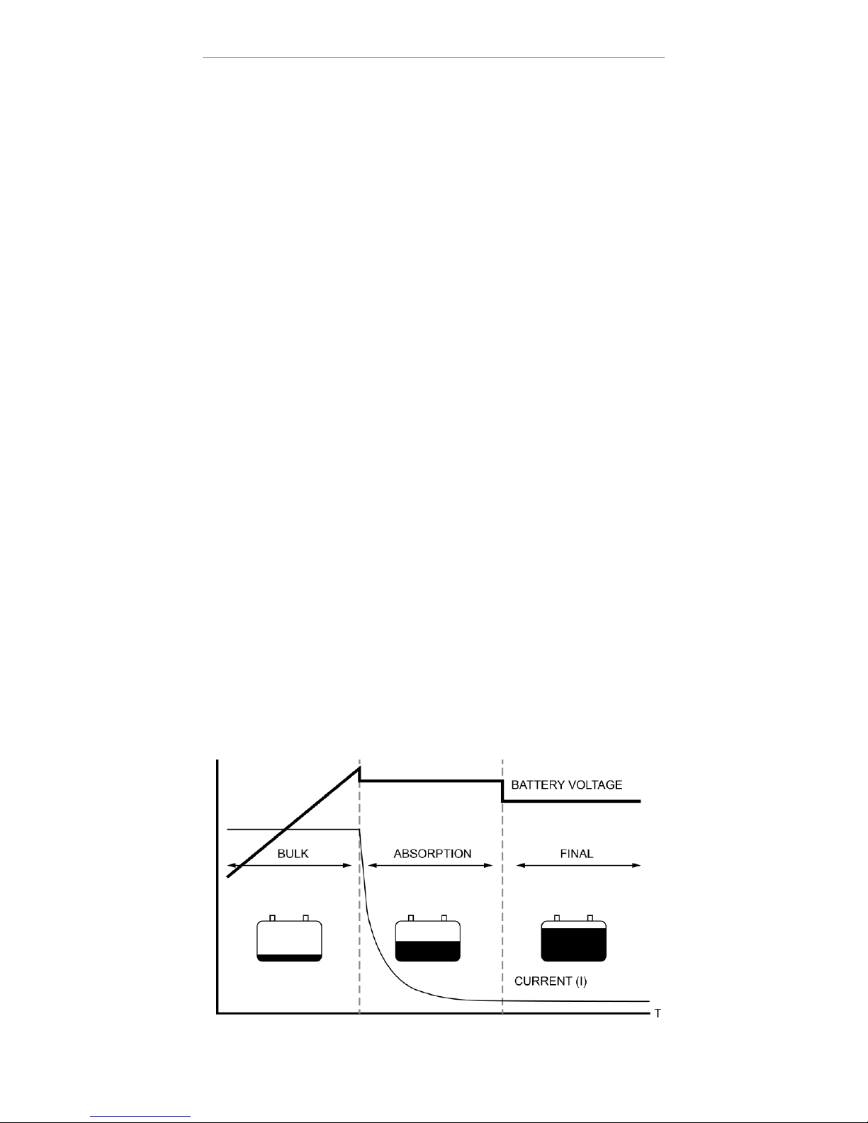
There are 4 charging stages in SL series, including an automatic 3-stage charging process (see Fig. 1): Bulk,
Absorb, and Final Charge; and a manual Equalization (EQ) charge stage. The automatic 3-stage charge
process provides complete recharging and monitoring of the batteries without damage due to overcharging.
The EQ stage (requires a remote display to enable) is used to stir up stratified electrolyte and to reverse any
battery plate sulfation that may have occurred.If the AC input voltage falls below 90 VAC – the charger will stop
charging to help stabilize the incoming AC voltage.
4-1-2. Bulk Charging
While bulk charging, the charger supplies the battery with controlled constant current. The charger will remain
in bulk charge until the absorption charge voltage (determined by the Battery Type selection) is achieved.
4-1-3. Absorption Charging
This is the second charging stage and begins after the absorb voltage has been reached. Absorb charging
provides the batteries with a constant voltage and reduces the DC charging current in order to maintain the
absorb voltage setting.
4-1-4. Final Charging
The third charging stage starts at the end of the absorb charging . While final charging, the charge voltage is
reduced to the final charge voltage (determined by the Battery Type selection*). In this stage, the batteries are
kept fully charged and ready if needed by the inverter. The Float Charging stage reduces battery gassing,
minimizes watering requirements (for flooded batteries), and ensures the batteries are maintained at optimum
capacity.
Fig. 10
:
Three step charge system
Page 19
15
4-1-5. Equalization Charging
The intent of this charging procedure is active between abs and final is to remove sulfation that formed as a
result of the batteries being undercharged.
Another objective is to bring all cells to an equal state of charge. While Equaliztion charging,the charge voltage
increase to 14.1V continue a cycle is 240 minute(automatic shutdown). During equalizing charge, check the
changes in the SG reading every hour and disconnect the charge when the gravity no longer rises. This is the
time when no further improvement is possible and a continued charge would have a negative effect on the
battery. The frequency of the equalizing charge is something that each battery manufacturer differs on. For
example, some will recommend be applied every month or every ten cycles, while another will recommend
every six months or every 20 cycles.
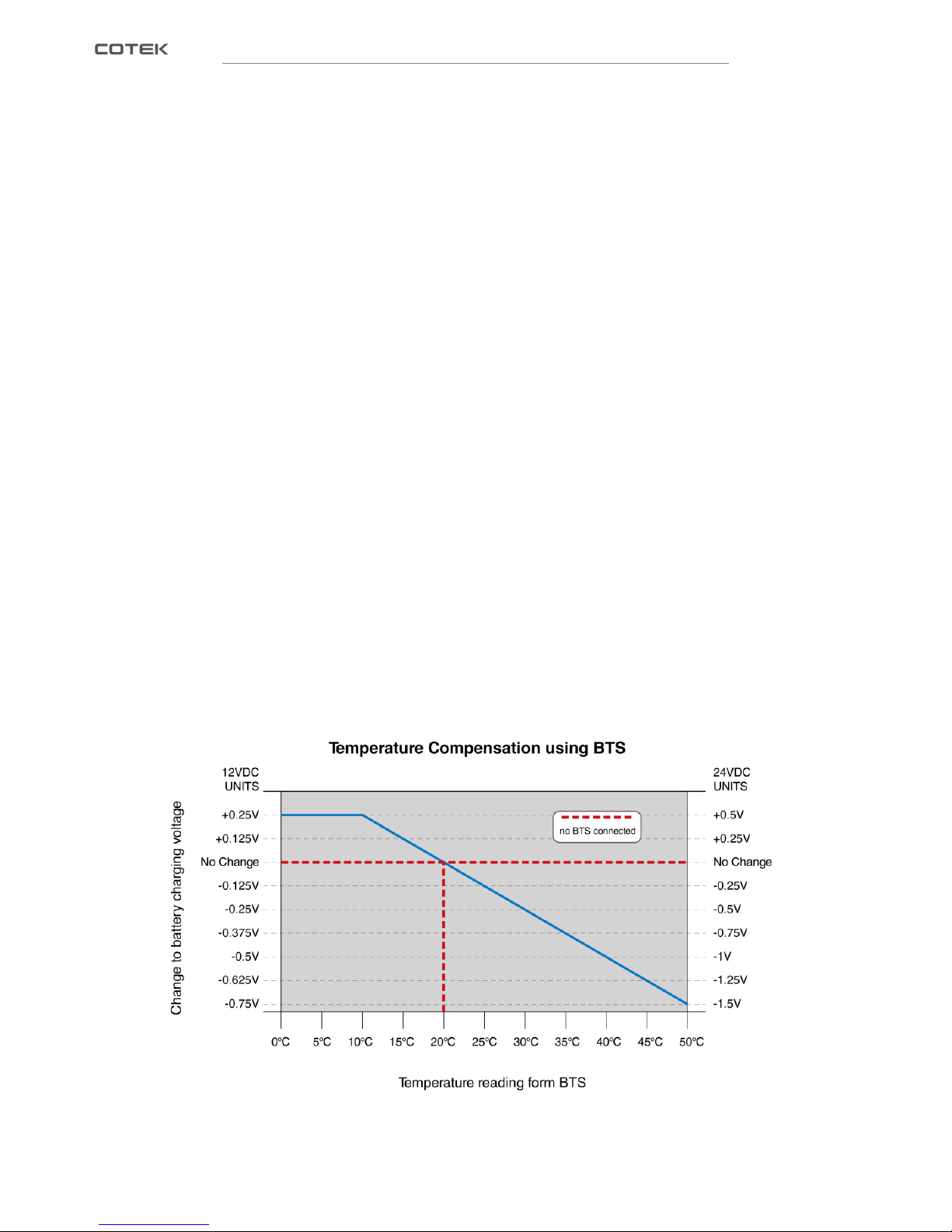
4-1-6. Temperature Compensated Charging
The unit is delivered with a battery temperature sensor (BTS). By installing this battery temperature sensor the
charge voltages are automatically adapted for deviating temperature.
With a BTS installed, if the temperature around the BTS is below 20°C the absorb and float charge voltage
increases, If the temperature around the BTS is higher than 20°C, the absorb and float charge voltage
decreases. See Fig. 11 to determine how much the charge voltage changes (increases or decreases)
depending on the temperature reading of the BTS. For example, the nominal absorb charge voltage for a
flooded battery at 20°C on a 12-volt model is 14.6 VDC. If the battery temperature is 35°C, the absorb charge
voltage would decrease to 14.225 VDC (14.6 VDC - 0.375 change). If the temperature sensor is NOT installed,
the charge voltages will not be automatically adjusted by temperature, but will be maintained at a temperature
of 20°C. The life of the batteries may be reduced if they are subjected to large temperature changes when the
BTS is not installed.
Fig. 11:Temperature compensation using BTS
Page 20
16
4-1-7. Charger Setting for various battery types
The following table gives the Absorption, Float and Equalization voltage settings for batteries commonly used:
Battery Type
Inverter
Voltage
Absorption
Voltage
Float
Voltage
Equalization
Voltage
Gel
12 VDC
14.1VDC
13.6VDC
NOTE!
Flooded
14.6VDC
13.4VDC
15.5VDC
AGM 1
14.3VDC
13.1VDC
15.5VDC
AGM 2
14.5VDC
13.5VDC
NOTE!
Custom*
12~16VDC
12~16VDC
12~16VDC
*User can be setting the custom function voltage, but must use LCD remote control or
RS-232 (See chapter“6” for more information).
Table 4:Various battery type charging setting
NOTE
Gel and the AGM 2 Group (East Penn / Deka / Discover / Trojan brand) batteries are not equalized.
Hence, their Equalization Voltages are same as the Absorption Voltages.
WARNING!
When using the Custom setting, the Equalization voltage setting should not allow voltage lower than
the Absorption Voltage setting. Also, the Equalization Voltage setting should not allow a setting
higher than 2-volts (for 12V systems) above the Absorb Voltage setting.
4-2. Operation mode introduction
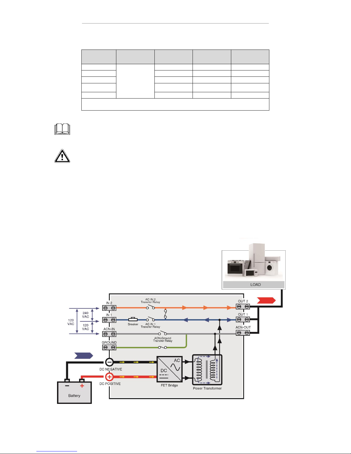
There are four Operation mode : 1.Basic 2.Charger 3.Power sharing 4.Generator operation modes.
4-2-1. Basic Mode
When there is no external “AC input” power available, the inverter of the unit provides AC power output load
from the batteries. There is no AC power available on the “AC output load”. See Fig. 12.
Fig. 12:Basic mode
Page 21
17
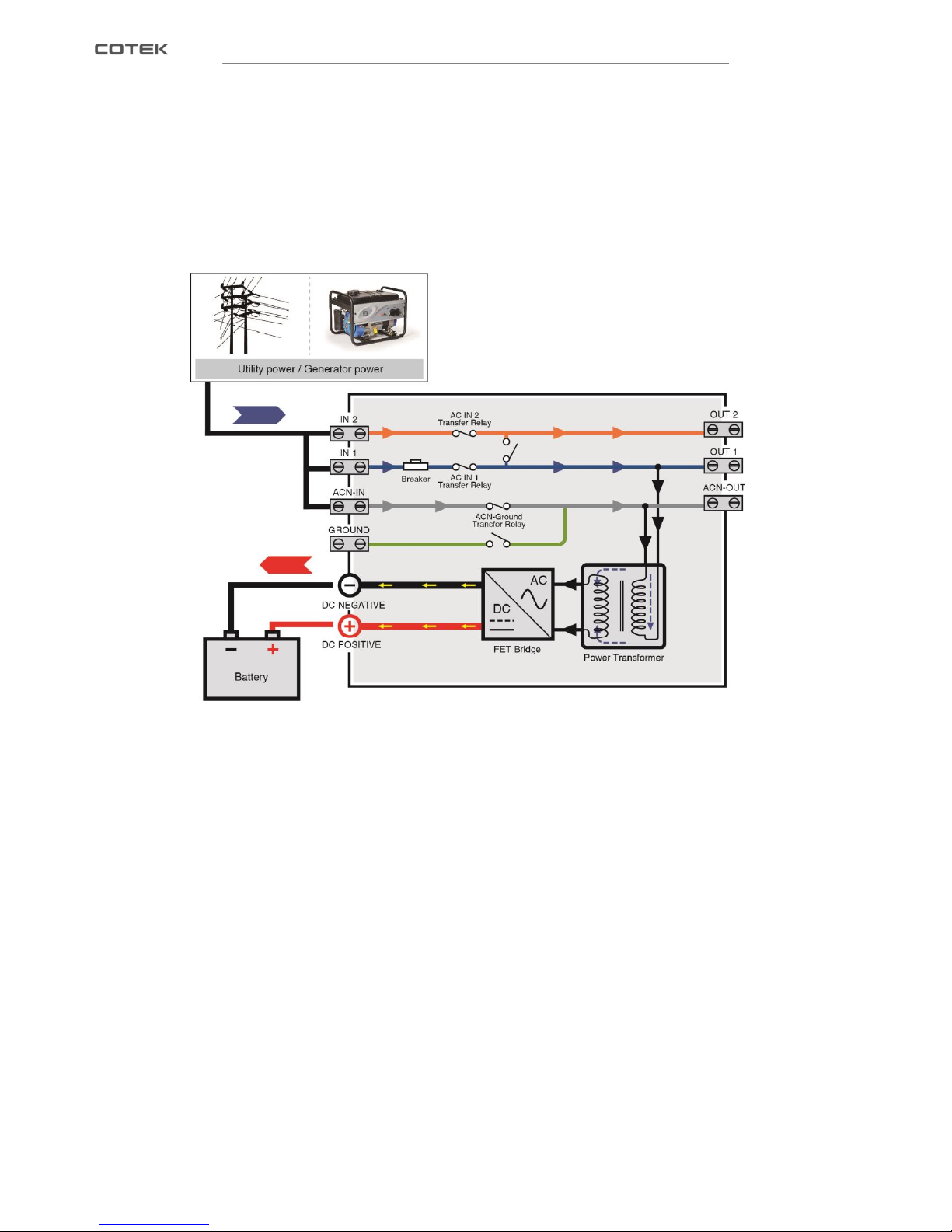
4-2-2. Charger Mode
When external AC power comes available, the transfer relay switches on. See Fig. 13.. The batteries are being
recharged now. (If only one phase AC input is available, please connect to IN1 and ACN-IN)
Fig. 13
:
Charger mode
4-2-3. Power Sharing Mode
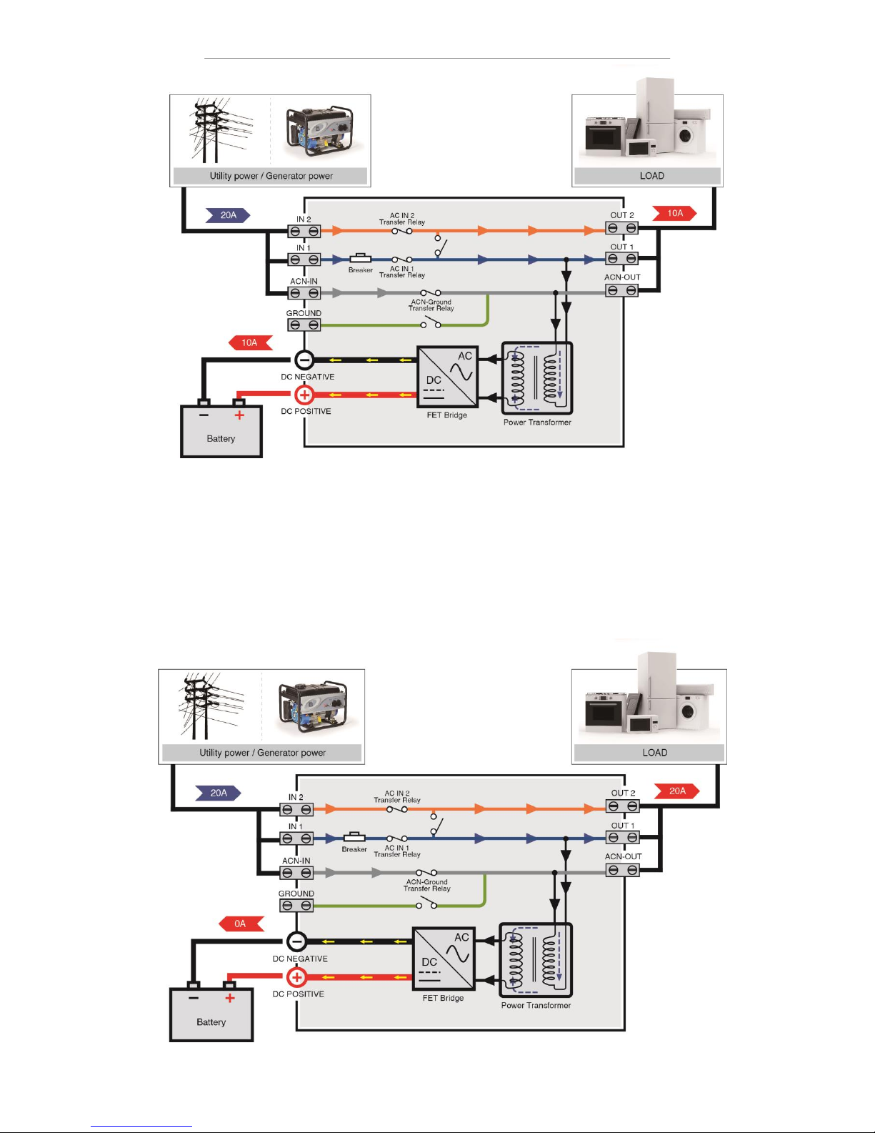
If the available power at the AC-input is limited, and the load connected to the AC output load increases, the
external AC circuit breaker may trip accordingly. To avoid this, SL series can automatically reduce the battery
charger output, and thus the AC power consumption. This Power sharing feature constantly senses the
incoming AC current which is used to supply both the battery charger and the appliances connected to the AC
output load.
The Power Sharing level should be set to match the value of the external circuit breaker, which protects the
incoming AC power.
Page 22
18
Fig. 14:Power Sharing Mode I
Example:
In Fig.14, Input AC current level is set to a 20 Amps while the AC output loads consume a total of 10Amps. This
means that only 20 – 10 = 10 Amps is left over for charging.
The input AC current level can be set only by remote control. When the total connected AC load reaches the
level of the Power Sharing setting (20A), there will be no power left over to charge the battery. This means that
the charge current of the unit will be reduced to 0A. See Fig.15.
Fig. 15:Power Sharing Mode II
Page 23
19
4-2-4. Generator Mode
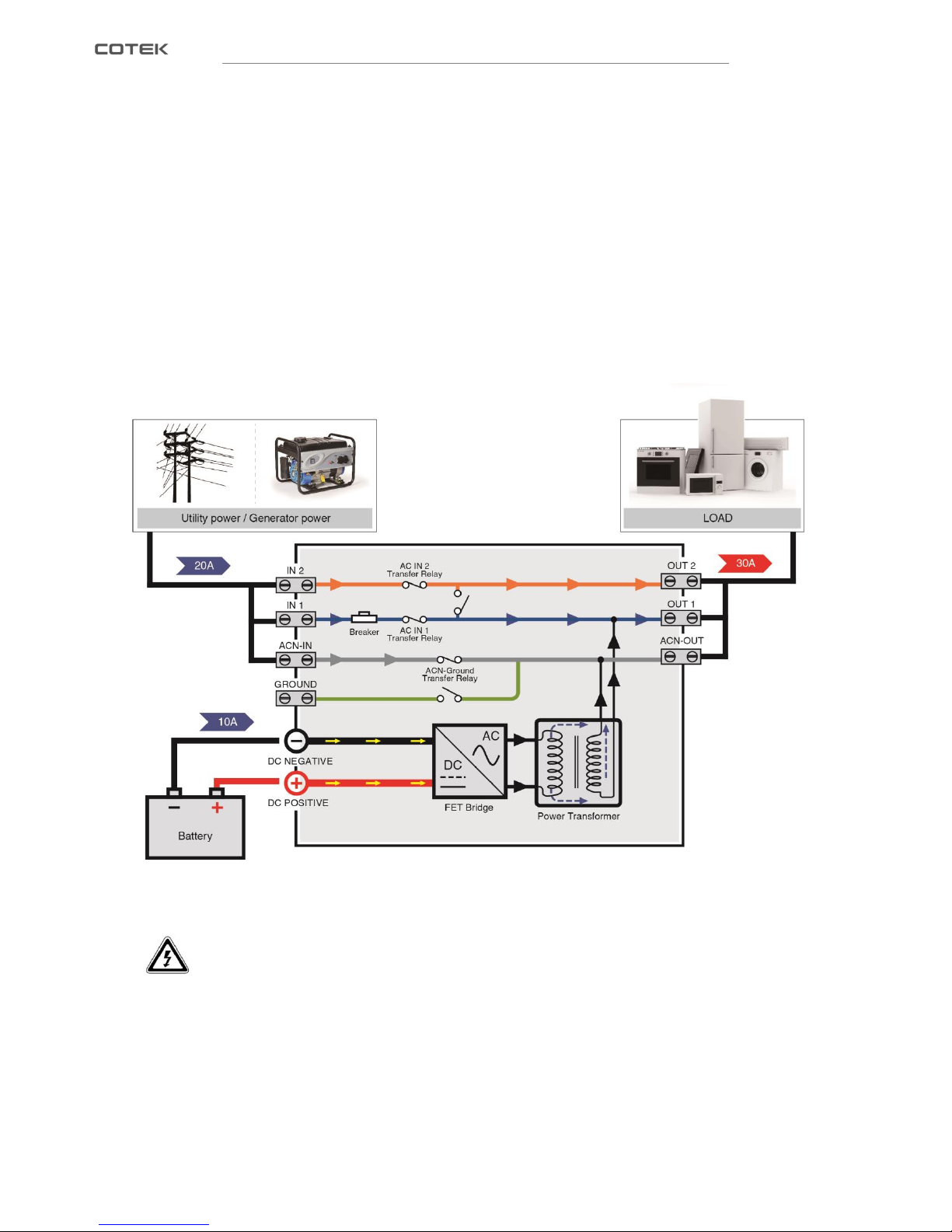
If the demand for AC power still increases, the external AC circuit breaker may still trip if nothing is done. This
problem can be solved by the Generator function. If the total demand for energy exceeds the maximum external
power supply, energy can be added to the AC outputs load by means of the inverter
Example
See Fig. 16, Input AC current is still limited to 20 Amps. This is not enough to supply the total load (30A)
connected to the AC output load, and the current form battery (Inverter) will supply the remaining 30 – 20 = 10A.
This means that the restricted amount of external AC power will be supported by energy from batteries.
Fig. 16:Generator Mode
CAUTION
For safety unit the transfer relay is immediately switched off when incoming AC power fails in
operation so that there will never be a high voltage on the shore cable inlet when it is not connected.
Page 24
20
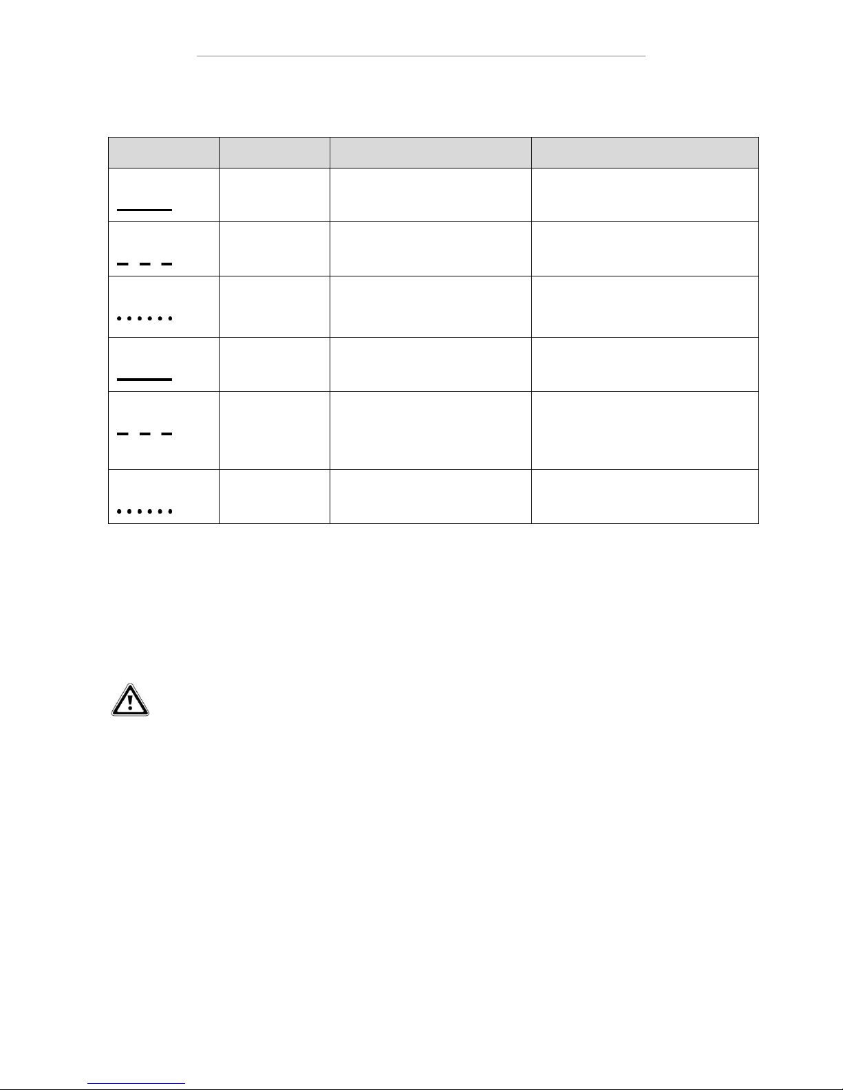
5. Trouble Shooting
LED Status
BUZZER Status
Description
Solution
Solid Red
Power off
Check power switch
Red Blink
Three Short
Over Voltage Protection
(Input DC voltage over spec)
Check input voltage. reduce input voltage
Red Fast Blink
Two Short
Under Voltage Protection
(Input DC voltage under spec)
1.Check connections and cable
2.Recharge battery
Orange solid
Five Short
Over Load Protect /Short-circuit
Protect
Reduce load in case of restart failed,
please turn on the unit manually
Orange Blink
One Short
Over Temp. Protect
Improve ventilation. Make sure ventilation
openings in inverter are not obstructed.
Reduce ambient temperature
Orange Fast Blink
Four Short
Under Temp. Protect
increase ambient temperature
Table 5:INV./CHR. Mode LED and buzzer indicator
6. Warranty
Warning!
Do not open or disassemble the Inverter. Attempting to do so may cause risk of electrical shock or
fire.
We guarantee this product against defects in materials and workmanship for a period of 24 months from the
date of purchase. In case you need to repair or replace any defective power inverters, please contact COTEK
local distributor.
This warranty will be considered void if the unit has been misused, altered, or accidentally damaged. COTEK is
not liable for anything that occurs as a result of the user’s fault.
Page 25

No.33, Sec. 2, Renhe Rd., Daxi Dist., Taoyuan City 33548, Taiwan
Phone:+886-3-3891999 FAX:+886-3-3802333
http:// www.cotek.com.tw
2018.3_A1
 Loading...