

Page 1

SK Series
Pure Sine Wave Inverter
User’s Manual
Page 2

Table of Contents
1. Important Safety Information.……………………………………………… 1
1-1 General Safety Precautions…………………………………………… 1
1-2 Battery Precautions………………………..………………………….. 1
2. Features………………………………………………………………………... 2
2-1 Application………………………………………………………………. 2
2-2 Electrical Performance………………………………………………… 3~7
2-3 Mechanical Drawings………………………………………………….. 8~9
3. Introduction…………………………………………………………………… 10
3-1 Front Panel operation….……………………………………………... 10~13
3-2 Rear Panel operation.………………………………………………… 14~15
3-3 Protections Features…………………………………………………… 15
3-4 Installation………………………………………………………………. 16
3-5 Making DC Wiring Connections ……………………………………... 17~19
3-6 AC Safety Grounding………………………………………………….. 20
3-7 Inverter Operation……………………………………………………… 21
4. Troubleshooting guide……………………………………………………… 22
5. Maintenance…………………………………………………………………… 23
6. Warranty……………………………………………………………………….. 23
Page 3
1. Important Safety Instructions
WARNING!
Before using the Inverter, read and save the safety
instructions.
1
1-1. General Safety Precautions
1-1-1. Do not expose the Inverter to rain, snow, spray, bilge or dust.
To reduce risk of hazard, do not cover or obstruct the ventilation
openings. Do not install the Inverter in a zero-clearance compartment.
Overheating may result.
1-1-2. To avoid a risk of fire and electronic shock, make sure that existing
wiring is in good electrical condition and not undersized.
Do not operate the Inverter with damaged or substandard Wiring.
1-1-3. There are some components in the inverter can cause arcs and sparks.
To prevent from fire or explosion, do not put batteries, flammable
materials, or anything should be ignition–protected around the inverter.
1-2. Precautions When Working with Batteries
1-2-1. If battery acid contacts skin or clothing, you shall wash it out with soap
and water immediately. If battery acid contacts your eyes, you shall
wash it out with cold running water for at least 20 minutes and get
medical attention immediately.
1-2-2. Never smoke or make a spark or flame in the vicinity of the battery or
the engine.
1-2-3. Do not drop a metal tool on the battery. The resulting spark or
short-circuit on the battery of other electrical part may cause an
explosion.
1-2-4. Remove personal metal items such as rings, bracelets, necklaces,
and watches when operating with a lead-acid batteries.
Doing so may cause short circuit and very high temperature, which can
melt metal items and even burn you.
1
Page 4

2. Features
Pure sine wave output (THD < 3%)
Output frequency:50 / 60Hz switch selections
Input & output fully isolated design
Power Saving Mode to conserve energy
High efficiency 89~94%
Driving highly reactive & capacitive loads at start moment
Tri-Color indicators show input voltage & output load level
Loading controlled cooling fan
Advanced microprocessor
Protection:Input low voltage Overload Short circuit
Low battery alarm Input over voltage Over temperature
2-1. Application
2-1-1. Power tools – circular saws, drills, grinders, sanders, buffers, weed
and hedge trimmers, air compressors, etc.
2-1-2. Office equipment – computers, printers, monitors, facsimile machines,
scanner, etc.
2-1-3. Household appliances – vacuum cleaners, fans, fluorescent and
incandescent lights, shavers, sewing machines.
2-1-4. Kitchen appliances – coffee makers, blenders, ice markers, toasters,
etc.
2-1-5. Industrial equipment – metal halide lamp, high – pressure sodium lamp,
etc.
2-1-6. Home entertainment electronics – television, VCRs, video games,
stereos, musical instruments, satellite equipment, etc.
2
Page 5
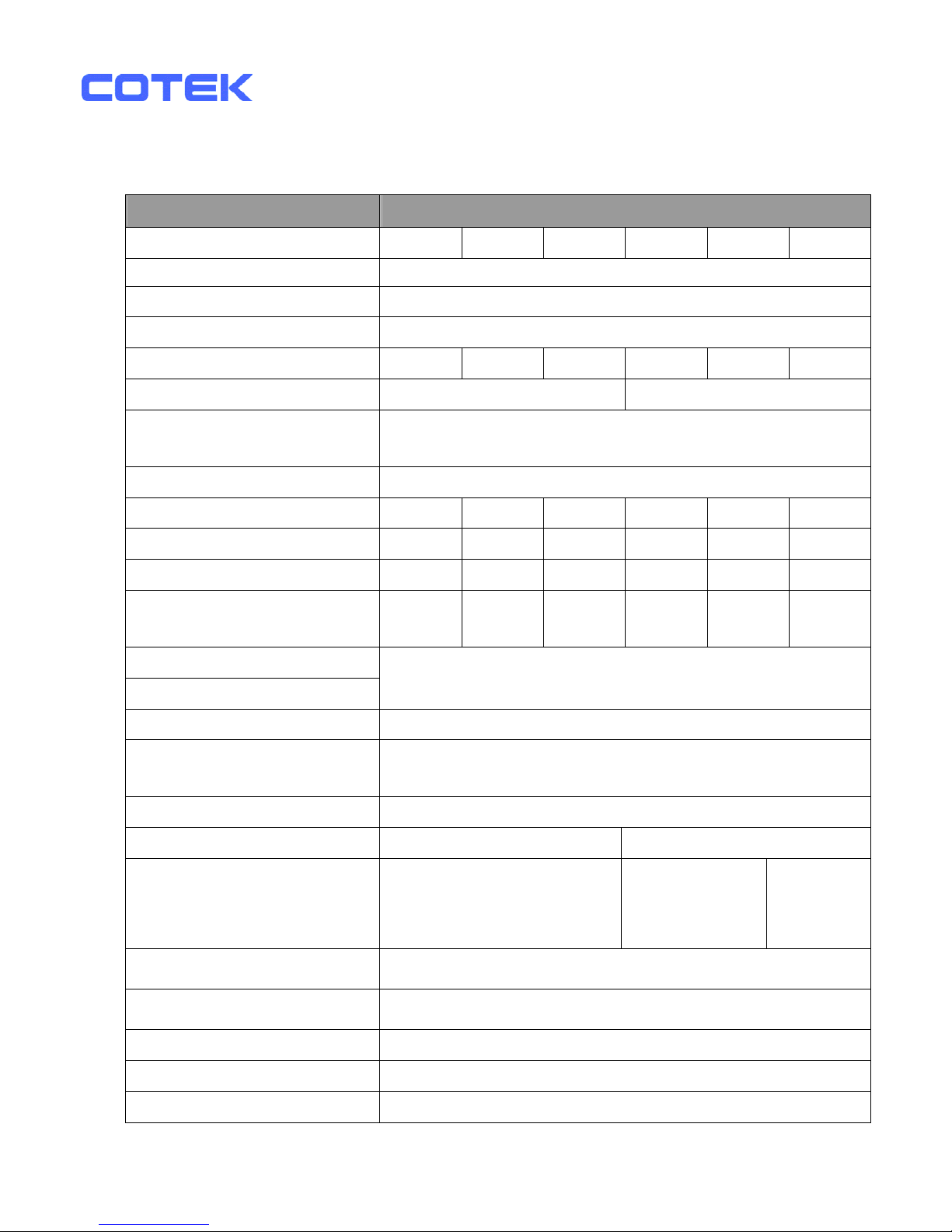
2-2. Electrical Performance
Specification
Model No.
Item
SK700-112 SK700-124 SK700-148 SK700-212 SK700-224 SK700-248
Continuous Output Power 700W
Maximum Output Power 770W
Surge Rating (Max.) 1400W
Input voltage 12V 24V 48V 12V 24V 48V
Output Voltage
100 / 110 / 120V +/- 3% 220 / 230 / 240V +/- 3%
Frequency
(Switch Selections)
50 / 60Hz +/- 0.05%
Output Waveform Pure Sine Wave ( THD < 3% )
Efficiency (full load) Max.
*1
89.0% 91.0% 92.0% 91.0% 93.0% 94.0%
No Load Current Draw (Max.) 1.25A 0.64A 0.31A 1.20A 0.60A 0.28A
Stand-By Current Draw (Max.) 0.25A 0.15A 0.08A 0.25A 0.15A 0.08A
Input Voltage Regulation
10.5-15
VDC
21.0-30
VDC
42-60
VDC
10.5-15
VDC
21.0-30
VDC
42-60
VDC
Input Level Indicator
Load Level Indicator
Red / Orange / Green LED
Failure Indicator Red LED
Protection
Overload, Short Circuit, Reverse Polarity (Fuse),
Over / Under Input Voltage, Over Temperature.
Remote Control Unit CR-6 / CR-7 / CR-8 Optional
Safety Cert. Meet UL458 EN60950-1
EMC FCC Class A
EN55022: 1997
EN55024: 1997
EN61000-3-2: 1998
EN61000-3-3: 1995
e-mark
e13 022986
Operating Temperature Range
0 - 40 ℃
Storage Temperature Range
-30℃ to 70℃
Cooling Loading controlled cooling fan
Dimensions 295(L)*180(W)*72(H)mm / 11.61(L)*7.09(W)*2.83(H) Inch
Weight 2.7kg / 5.4 Lbs.
Page 6
Note: The specifications are subject to change without notice.
3
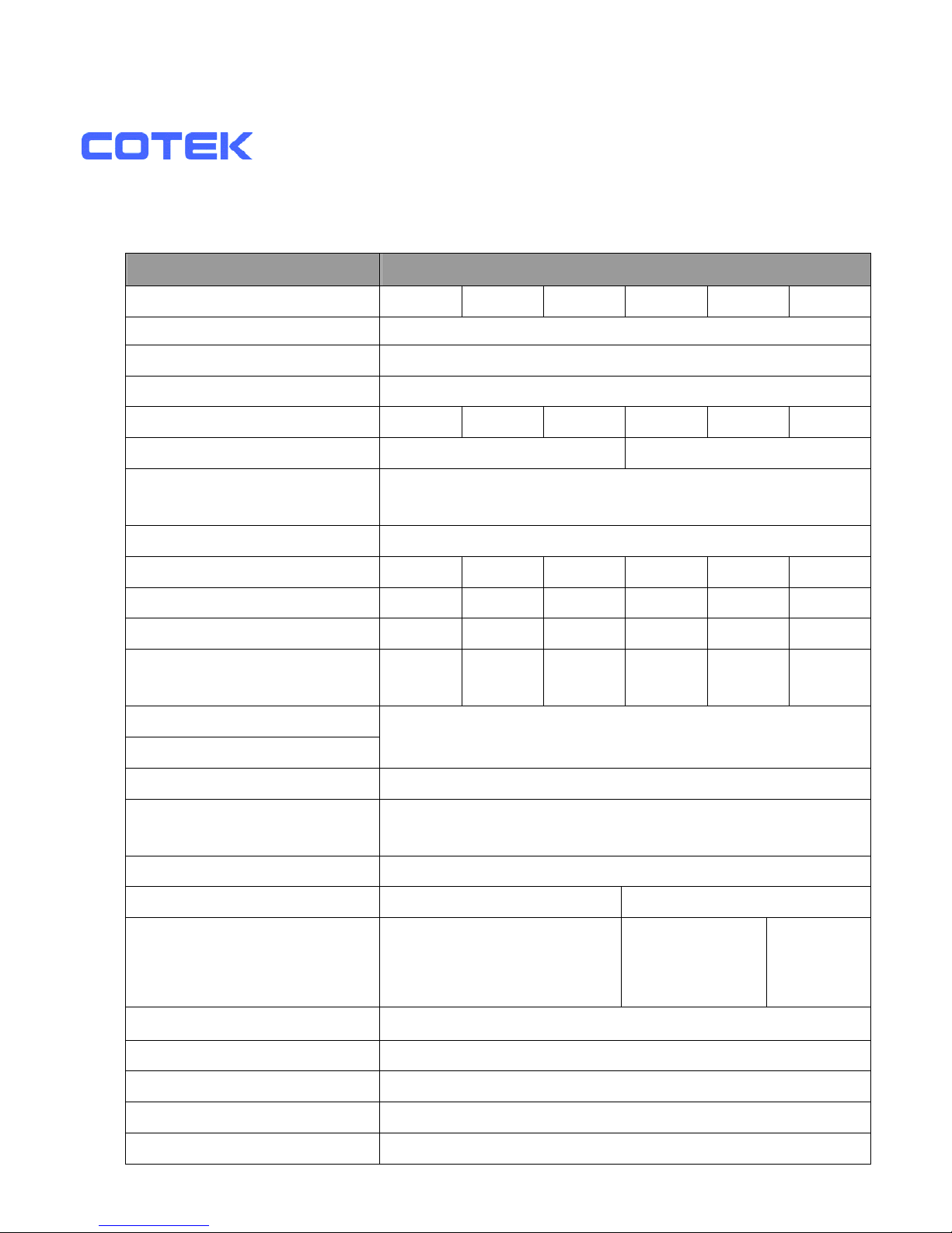
Specification
Model No.
Item
SK1000-112 SK1000-124 SK1000-148 SK1000-212 SK1000-224 SK1000-248
Continuous Output Power 1000W
Maximum Output Power 1100W
Surge Rating (Max) 2000W
Input voltage 12V 24V 48V 12V 24V 48V
Output Voltage
100 / 110 / 120V +/- 3% 220 / 230 / 240V +/- 3%
Frequency
(Switch Selectable)
50 / 60Hz +/- 0.05%
Output Waveform Pure Sine Wave ( THD < 3% )
Efficiency (full load) Max.
*1
89.0% 92.0% 93.0% 91.0% 94.0% 95.0%
No Load Current Draw (Max.) 1.43A 0.75A 0.38A 1.25A 0.65A 0.35A
Stand-By Current Draw (Max.) 0.25A 0.15A 0.09A 0.25A 0.15A 0.09A
Input Voltage Regulation
10.5-15
VDC
21.0-30
VDC
42-60
VDC
10.5-15
VDC
21.0-30
VDC
42-60
VDC
Input Level Indicator
Load Level Indicator
Red / Orange / Green LED
Failure Indicator Red LED
Protection
Overload, Short Circuit, Reverse Polarity (Fuse),
Over / Under Input Voltage, Over Temperature.
Remote Control Unit CR-6 / CR-7 / CR-8 Optional
Safety Certification UL458 EN60950-1
EMC FCC Class A
EN55022: 1997
EN55024: 1997
EN61000-3-2: 1998
EN61000-3-3: 1995
e-mark
e13 022694
Operating Temperature Range
0 - 40 ℃
Storage Temperature Range
-30℃ to 70℃
Cooling Loading controlled cooling fan
Dimensions 383(L)*182(W)*88(H)mm / 15.08(L)*7.17(W)*3.46(H) Inch
Weight 4 kg / 8.8 Lbs.
Page 7

Note: The specifications are subject to change without notice.
4
Page 8
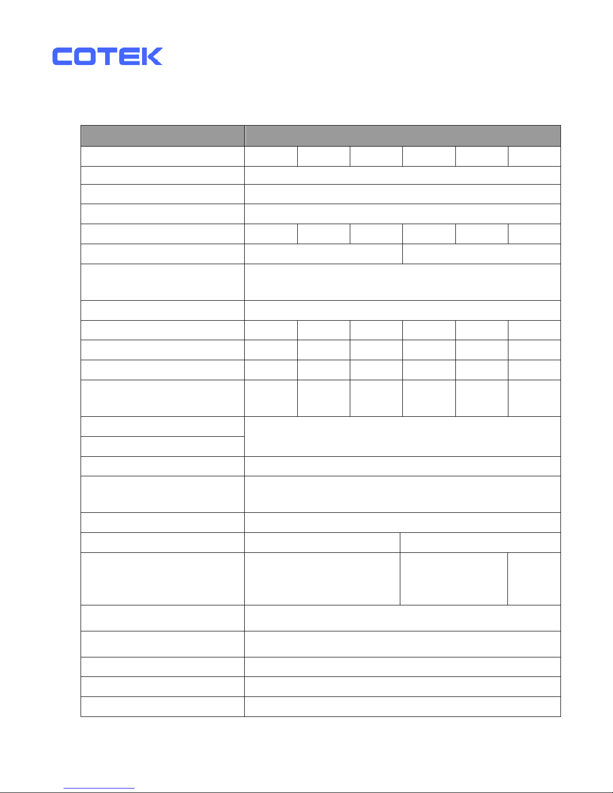
Specification
Model No.
Item
SK1500-112 SK1500-124 SK1500-148 SK1500-212 SK1500-224 SK1500-248
Continuous Output Power 1500W
Maximum Output Power 1650W
Surge Rating (Max) 3000W
Input voltage 12V 24V 48V 12V 24V 48V
Output Voltage
100 / 110 / 120V +/- 3% 220 / 230 / 240V +/- 3%
Frequency
(Switch Selectable)
50 / 60Hz +/- 0.05%
Output Waveform Pure Sine Wave ( THD < 3% )
Efficiency (full load) Max.
*1
88.0% 91.0% 92.0% 90.0% 93.0% 94.0%
No Load Current Draw (Max) 1.45A 0.75A 0.40A 1.40A 0.70A 0.40A
Stand-By Current Draw (Max) 0.28A 0.15A 0.09A 0.28A 0.15A 0.09A
Input Voltage Regulation
10.5-15
VDC
21.0-30
VDC
42-60
VDC
10.5-15
VDC
21.0-30
VDC
42-60
VDC
Input Level Indicator
Load Level Indicator
Red / Orange / Green LED
Failure Indicator Red LED
Protection
Overload, Short Circuit, Reverse Polarity (Fuse),
Over / Under Input Voltage, Over Temperature.
Remote Control Unit CR-6 / CR-7 / CR-8 Optional
Safety Certification Meet UL458 EN60950-1
EMC FCC Class A
EN55022: 1997
EN55024: 1997
EN61000-3-2: 1998
EN61000-3-3: 1995
e-mark
e13 22876
Operating Temperature Range
0 - 40 ℃
Storage Temperature Range
-30℃ to 70℃
Cooling Loading controlled cooling fan
Dimensions 415(L)*191(W)*88(H)mm / 16.34(L)*7.52(W)*3.46(H) Inch
Weight 4.8 kg / 10.56 Lbs.
Note: The specifications are subject to change without notice.
5
Page 9
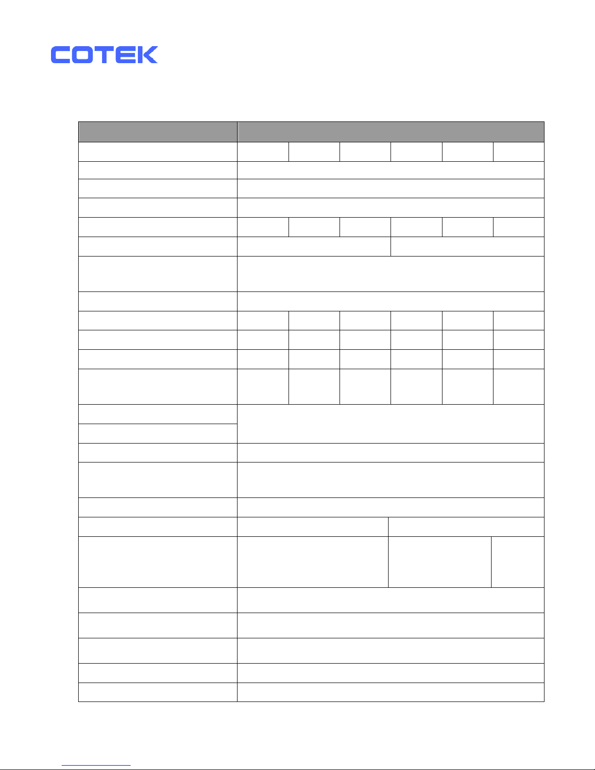
Specification
Model No.
Item
SK2000-112 SK2000-124 SK2000-148 SK2000-212 SK2000-224 SK2000-248
Continuous Output Power 2000W
Maximum Output Power 2200W
Surge Rating (Max) 4000W
Input voltage 12V 24V 48V 12V 24V 48V
Output Voltage
100 / 110 / 120V +/- 3% 220 / 230 / 240V +/- 3%
Frequency
(Switch Selectable)
50 / 60Hz +/- 0.05%
Output Waveform Pure Sine Wave ( THD < 3% )
Efficiency (full load) Max.
*1
89.0% 92.0% 93.0% 91.0% 94.0% 95.0%
No Load Current Draw (Max) 2.8A 1.5A 0.7A 2.64A 1.32A 0.65A
Stand-By Current Draw (Max) 0.60A 0.30A 0.15A 0.60A 0.25A 0.15A
Input Voltage Regulation
10.5-15
VDC
21.0-30
VDC
42-60
VDC
10.5-15
VDC
21.0-30
VDC
42-60
VDC
Input Level Indicator
Load Level Indicator
Red / Orange / Green LED
Failure Indicator Red LED
Protection
Overload, Short Circuit, Reverse Polarity (Fuse),
Over / Under Input Voltage, Over Temperature.
Remote Control Unit CR-6 / CR-7 / CR-8 Optional
Safety Certification Meet UL458 EN60950-1
EMC FCC Class A
EN55022: 1997
EN55024: 1997
EN61000-3-2: 1998
EN61000-3-3: 1995
e-mark
e13 22846
Operating Temperature Range
0 - 40 ℃
Storage Temperature Range
-30℃ to 70℃
Cooling
Loading controlled cooling fan ( 65℃ ON , 45℃ OFF)
Dimensions 422(L)*208(W)*166(H)mm / 16.6(L)*8.18(W)*6.53(H) Inch
Weight 9 kg / 19.8 Lbs.
Page 10

Note: The specifications are subject to change without notice.
6
Page 11
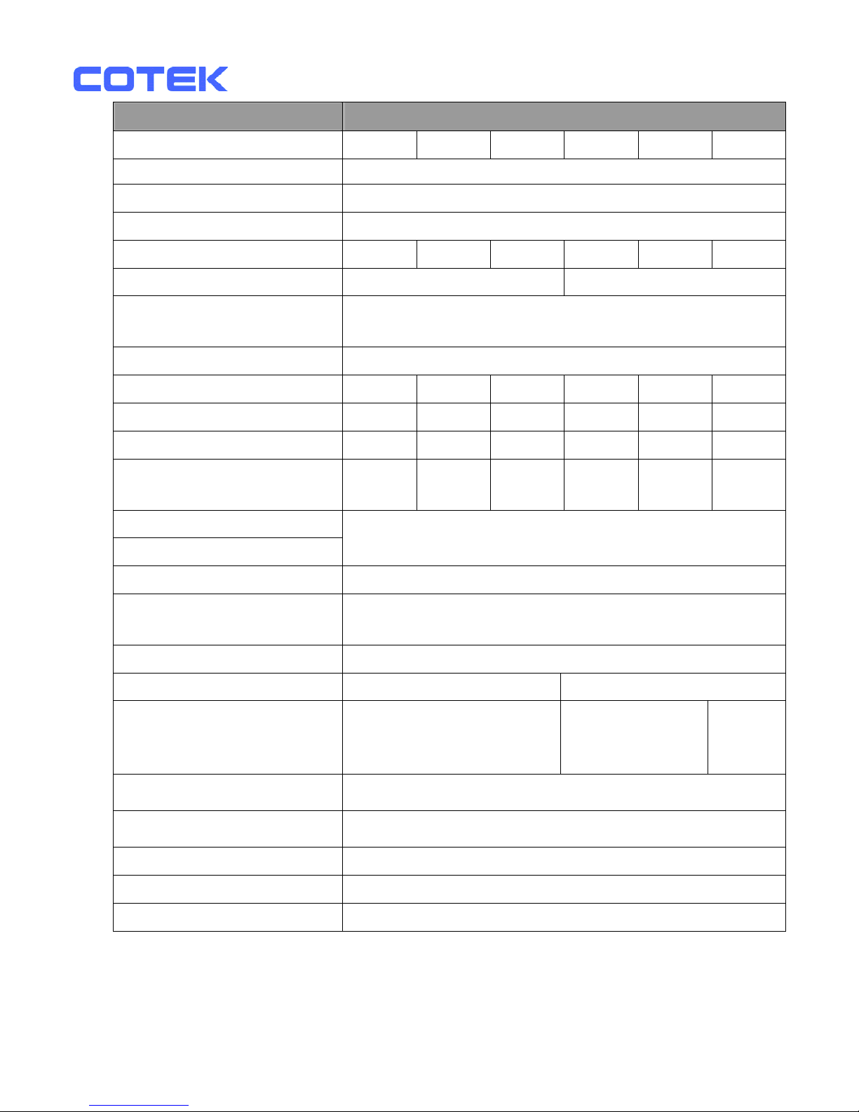
Specification
Model No.
Item
SK3000-112 SK3000-124 SK3000-148 SK3000-212 SK3000-224 SK3000-248
Continuous Output Power 3000W
Maximum Output Power 3300W
Surge Rating (Max) 6000W
Input voltage 12V 24V 48V 12V 24V 48V
Output Voltage
100 / 110 / 120V +/- 3% 220 / 230 / 240V +/- 3%
Frequency
(Switch Selectable)
50 / 60Hz +/- 0.05%
Output Waveform Pure Sine Wave ( THD < 3% )
Efficiency (full load) Max.
*1
88.0% 91.0% 92.0% 90.0% 93.0% 94.0%
No Load Current Draw (Max) 3.0A 1.6A 0.8A 2.8A 1.5A 0.7A
Stand-By Current Draw (Max) 0.55A 0.35A 0.19A 0.55A 0.35A 0.19A
Input Voltage Regulation
10.5-15
VDC
21.0-30
VDC
42-60
VDC
10.5-15
VDC
21.0-30
VDC
42-60
VDC
Input Level Indicator
Load Level Indicator
Red / Orange / Green LED
Failure Indicator Red LED
Protection
Overload, Short Circuit, Reverse Polarity (Fuse),
Over / Under Input Voltage, Over Temperature.
Remote Control Unit CR-6 / CR-7 / CR-8 Optional
Safety Cert. Meet UL458 EN60950-1
EMC FCC Class A
EN55022: 1997
EN55024: 1997
EN61000-3-2: 1998
EN61000-3-3: 1995
e-mark
e13 22845
Operating Temperature Range
0 - 40 ℃
Storage Temperature Range
-30℃ to 70℃
Cooling Loading controlled cooling fan
Dimensions 452(L)*208(W)*166(H)mm / 17.80(L)*8.18(W)*6.53(H) Inch
Weight 9.8 kg / 22 Lbs.
Note: The specifications are subject to change without notice.
*1 : This test condition is normal DC input (13.5V) and Temperature 25’C.
Page 12
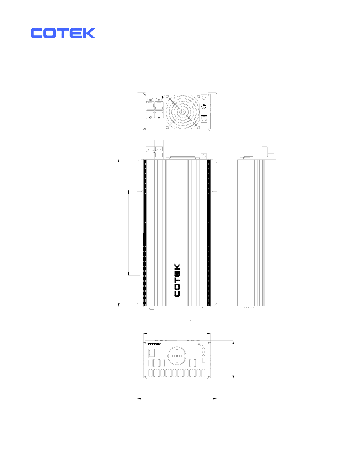
2-3. Mechanical Drawings
REMOTE
PORT
CHASSIS
GROUND
SK700 273.00 [10.75]
SK1000 340.00 [13.39]
SK1500 370.00 [14.57]
196.00 [7.72]
SK700 71.50[2.83]
SK1000 88.00[3.46]
SK1500 88.00[3.46]
SK700 179.00[7.05]
SK1000 182.00[7.17]
SK1500 191.00[7.52]
SK700 151.00[5 94]
SK1000 154.00 [6.06]
SK1500 163.00[6.42]
S3
S2
PWR.
SAV.
IO
S1
LOAD
LEVEL
INPUT
LEVEL
S4
STATUS
FREQ.
1000W
Pure Sine Wave Power Inverter
POS(+) NEG(-)
DC INPUT
REVERSE POLARITY
WILL DAMAGE UNIT
PURE SINE WAVE INVERTER
AC OUTPUT
ONON
REMOTE
OFF
I
0
8
Page 13
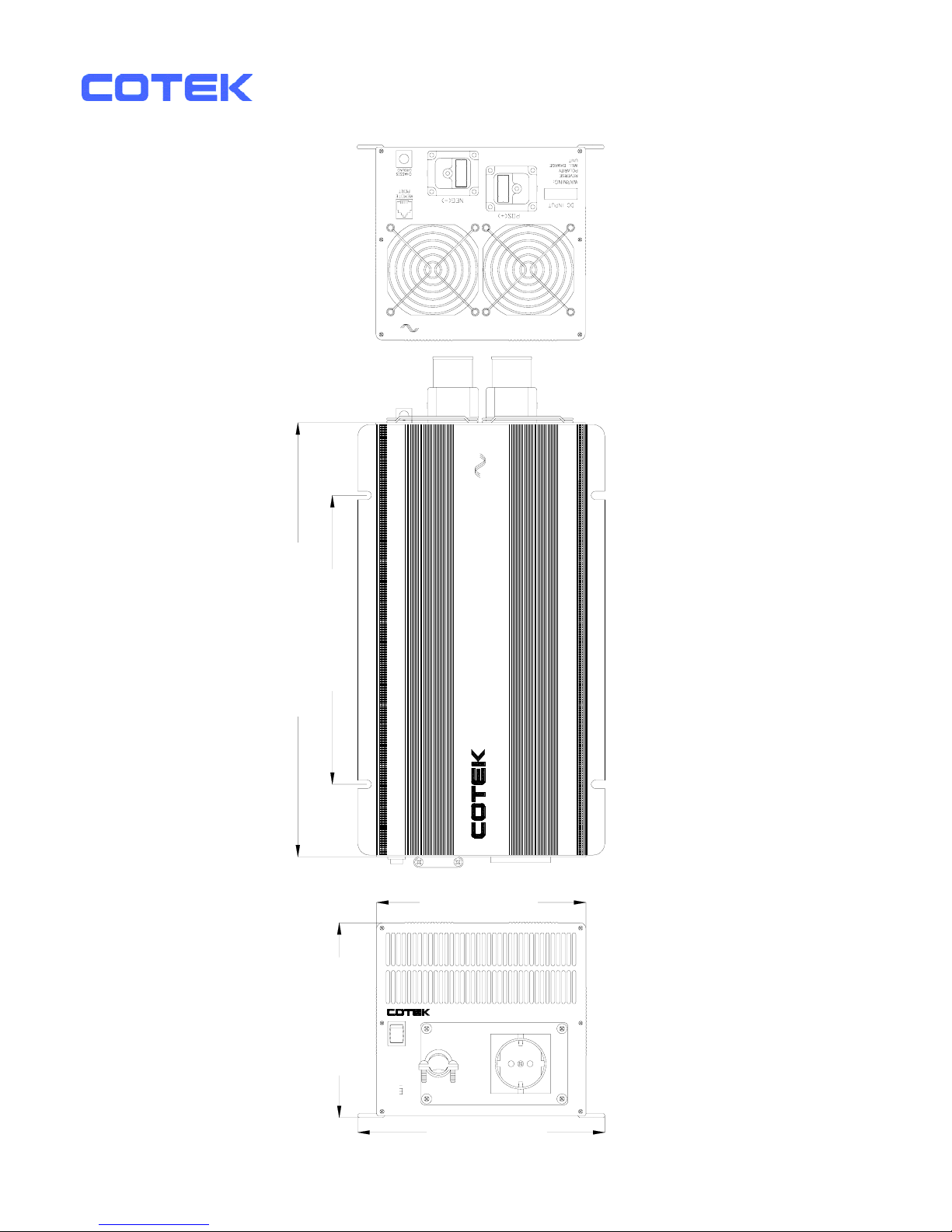
Pure Sine Wave Power Inverter
2000W
3000W
AC OUTPUT
OI
PURE SINE WAVE INVERTER
S4
S2
S1
S3
FREQ.
PWR.
SAV.
LOAD
LEVEL
STATUS
INPUT
LEVEL
OFF
ON
REMO.
0
I
SK2000 368.00 [14.49]
SK3000 398.00 [15.67]
245.00 [9.65]
177.00 [6.97]
209.00 [8.23]
165.25 [6.51]
9
Page 14
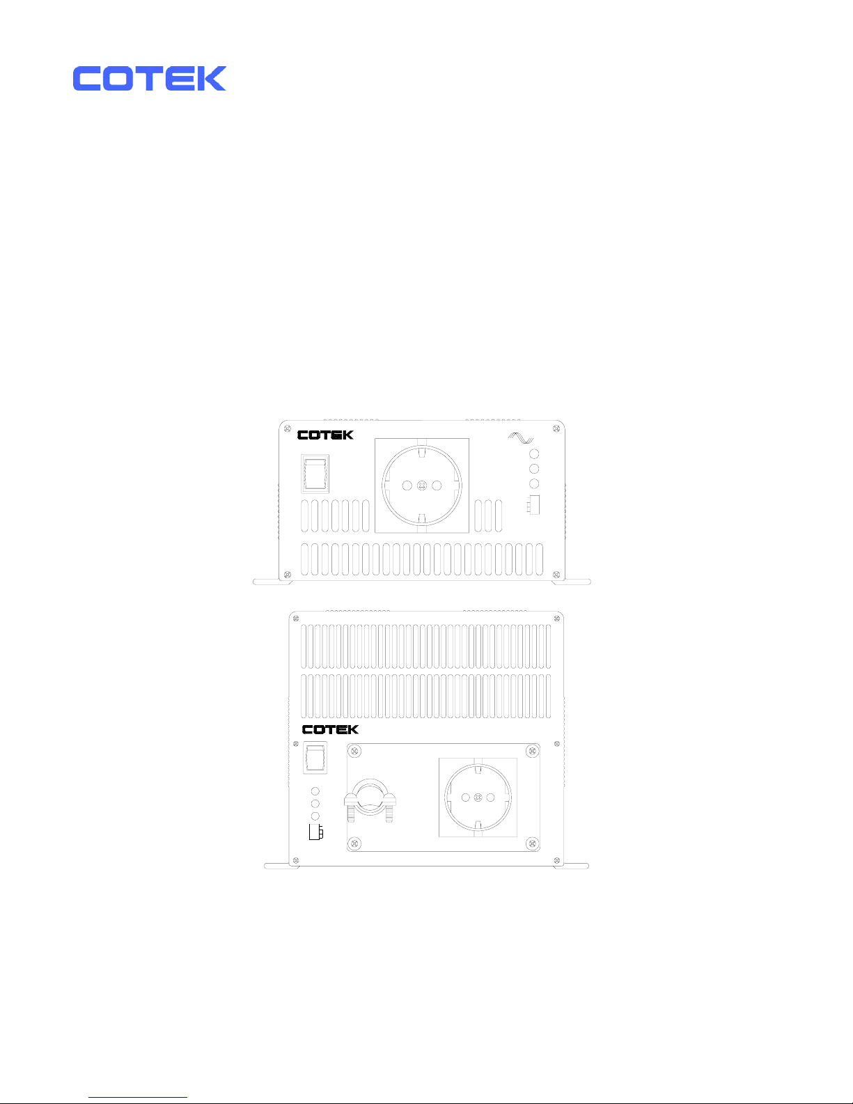
3. Introduction
This power inverter series is one of the most advanced line of mobile AC power
systems.
To get the most effective power inverter, it must be installed and used properly.
Please read the instructions of this manual before you install and operate this
model.
3-1. Front Panel Operations:
3-1-1. Front view:
PURE SINE WAVE INVERTER
AC OUTPUT
OFF
REMOTE
I
0
ONON
S1
PWR.
SAV.
OI
INPUT
LEVEL
FREQ.
STATUS
S4
LOAD
LEVEL
S2
S3
SK700
SK1000
SK1500
0
S4
S3
S1
S2
O
SK2000
SK3000
OI
FREQ.
PWR.
SAV.
LOAD
LEVEL
STATUS
INPUT
LEVEL
S4
S2
S1
S3
FREQ.
PWR.
SAV.
I
AC OUTPUT
PURE SINE WAVE INVERTER
REMO.
INPUT
LEVEL
STATUS
LOAD
LEVEL
I
ON
OFF
3-1-2. ON / OFF/ REMOTE (Main) switch:
Page 15

a. Before installing the inverter, you need to ensure the main switch
must be “OFF”.
b. Before using the remote unit, you need to ensure the main switch
must be “ REMOTE”.
10
Page 16
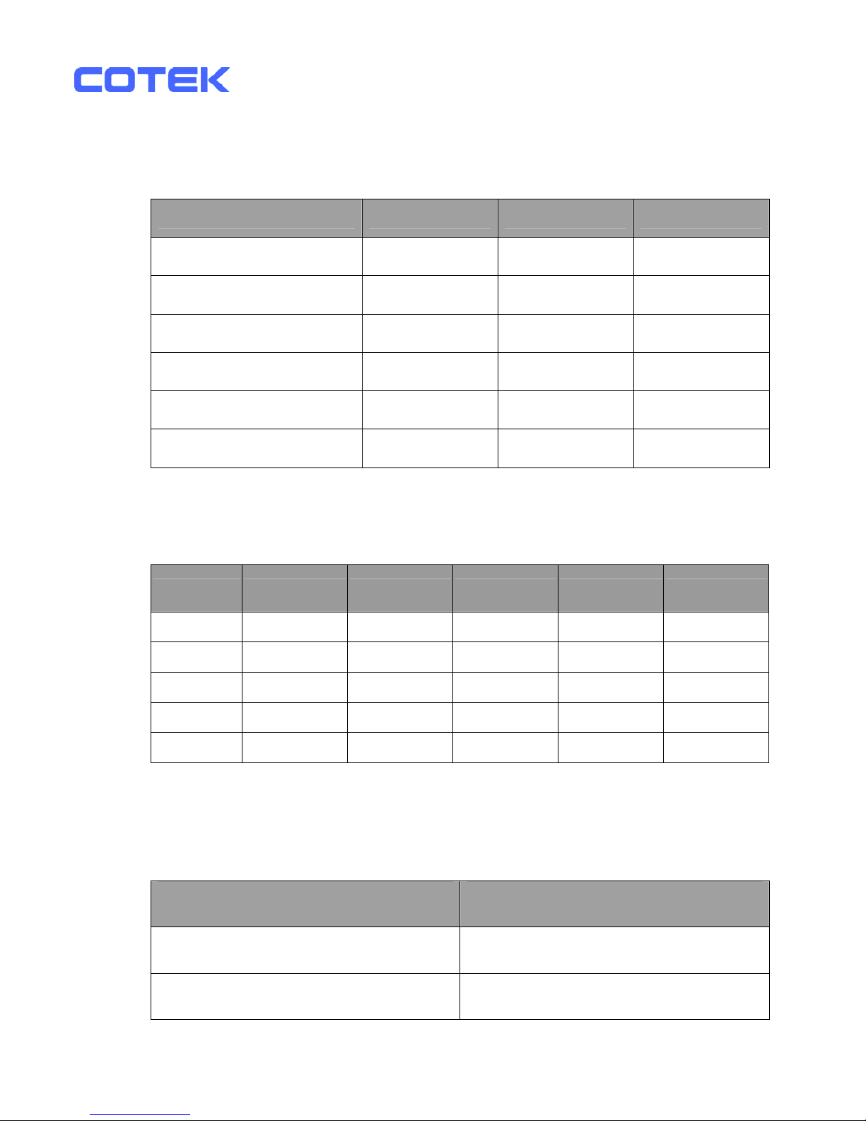
3-1-3. Input Level:Display Input Voltages
LED Status DC 12V DC 24V DC 48V
RED Slow Blink 10.5~10.9 21.0~21.8 42.0~43.6
RED 10.9~11.3 21.8~22.6 43.6~45.2
ORANGE 11.3~12.0 22.6~24.0 45.2~48.0
GREEN 12.0~14.0 24.0~28.0 48.0~56.0
ORANGE Blink 14.0~14.7 28.0~29.4 56.0~58.8
OVER RED Blink 14.7q 29.4q 58.8q
3-1-4. Load Level:Display AC Loads (Watts)
LED status DARK GREEN ORANGE RED RED BLINK
SK700
0 ~ 35W 35 ~ 230W 230 ~ 525W 525 ~ 672W Over 672W
SK1000
0 ~ 50W 50 ~ 330W 330 ~ 750W 750 ~ 960W Over 960W
SK1500
0 ~ 75W 75 ~ 495W 495 ~ 1125W 1125 ~ 1450W Over 1450W
SK2000
0 ~ 100W 100 ~ 660W 660 ~ 1500W 1500 ~ 1920W Over 1920W
SK3000
0 ~ 150W 150 ~ 990W 990 ~ 2250W 2250 ~ 2880W Over 2880W
3-1-5. AC Frequency:Selected by “S4” Dip Switch
Frequency S4
50 HZ OFF
60 HZ ON
11
Page 17
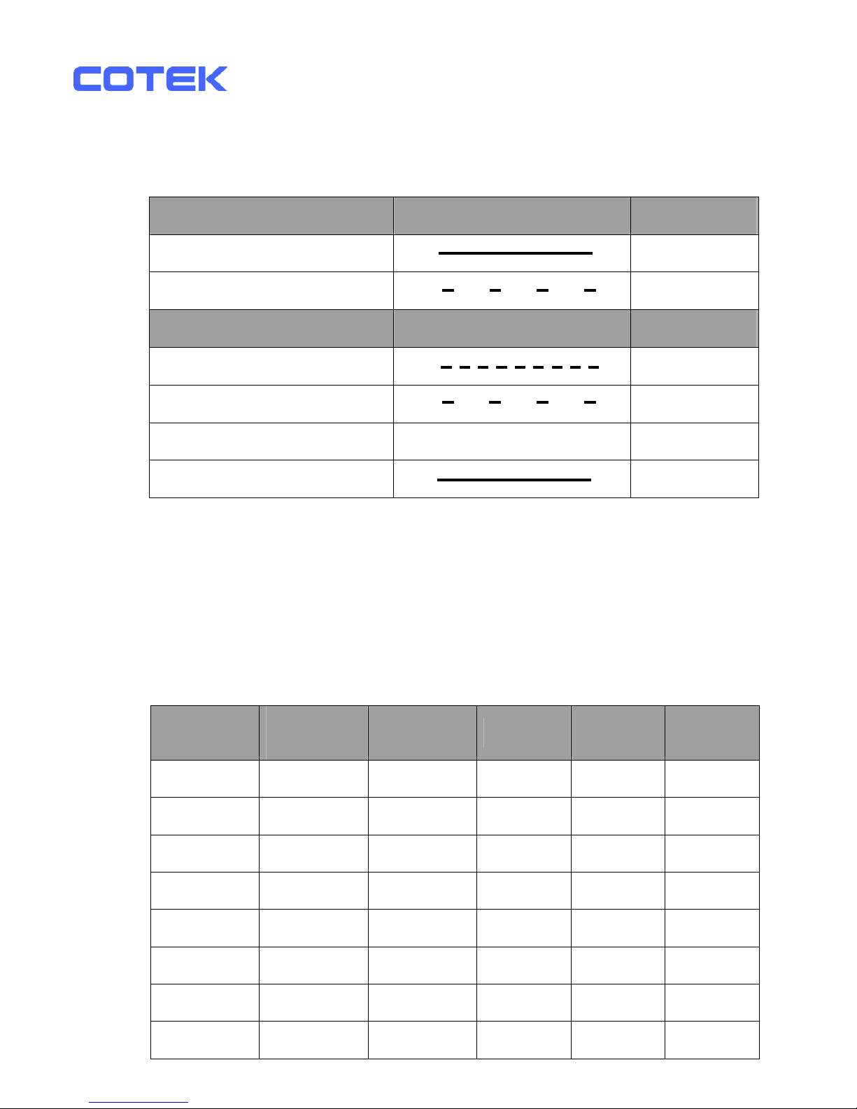
3-1-6. Status:Display Power & Fault Status
Green LED LED Signal Status
Solid Power OK
Slow Blink Power Saving
Red LED LED Signal Status
Fast Blink OVP
Slow Blink UVP
Intermittent Blink
OTP
Solid OLP
3-1-7. Power Saving Mode: Power Saving Mode is adjustable and
set by the Dip Switches, S1, S2 and S3 on the front panel.
Example: With the watt setting at 15W, a 15W↑ load will make the
inverter operate normally, a 15W↓ load will enter into the Power
saving mode.
SK700
SK1000
SK1500
SK2000
SK3000
S1 S2 S3
DISABLE DISABLE DISABLE OFF OFF OFF
15W 20W 40W ON OFF OFF
25W 40W 80W OFF ON OFF
40W 55W 125W ON ON OFF
50W 75W 170W OFF OFF ON
65W 95W 210W ON OFF ON
75W 115W 245W OFF ON ON
85W 135W 280W ON ON ON
12
Page 18
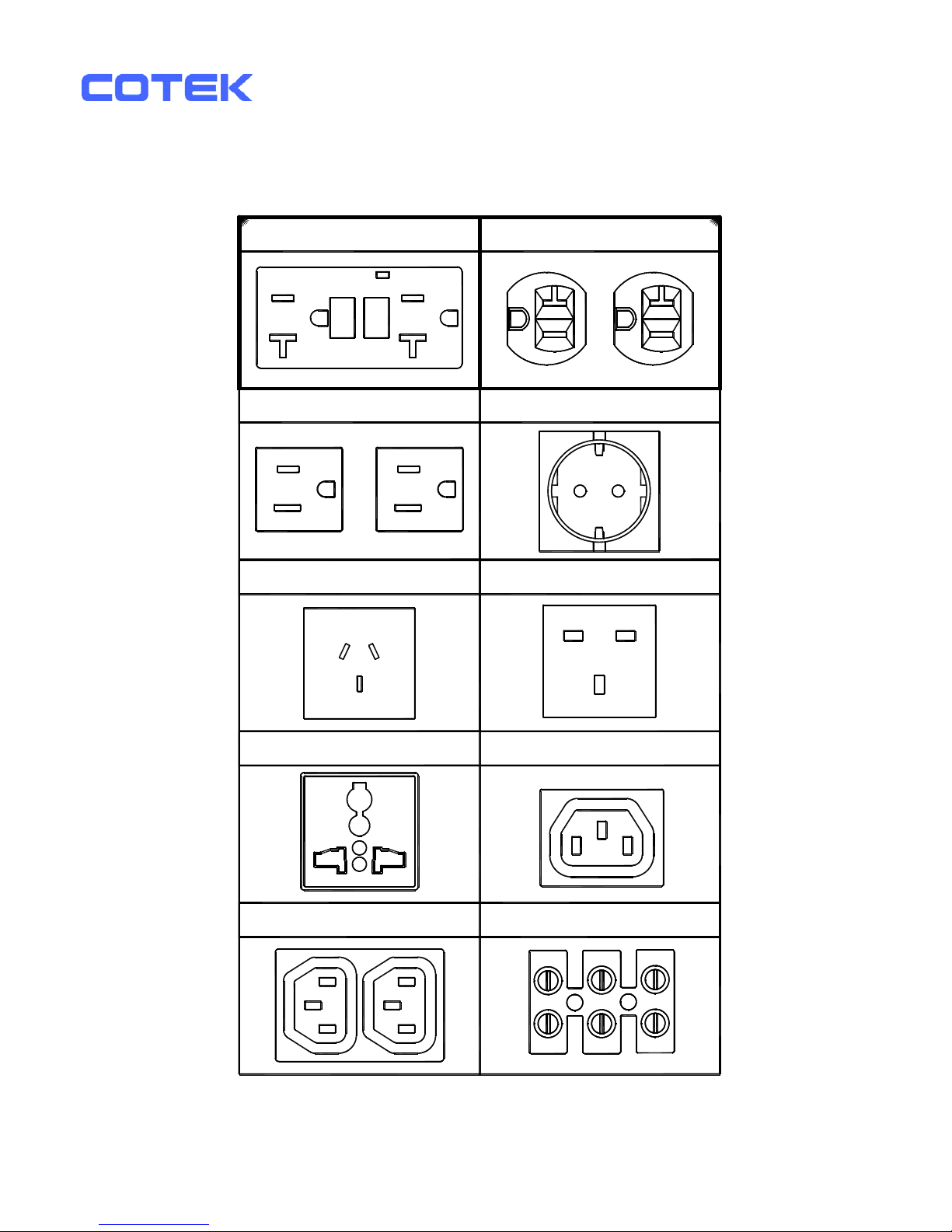
3-1-8. AC outlets (available):
NEMA 5-15R
HARD WIRE
Continental European
North America (GFCI)
IEC-1
United Kingldom
Universal
IEC-2
Australia / New Zealand
NEMA 5-20R
13
Page 19
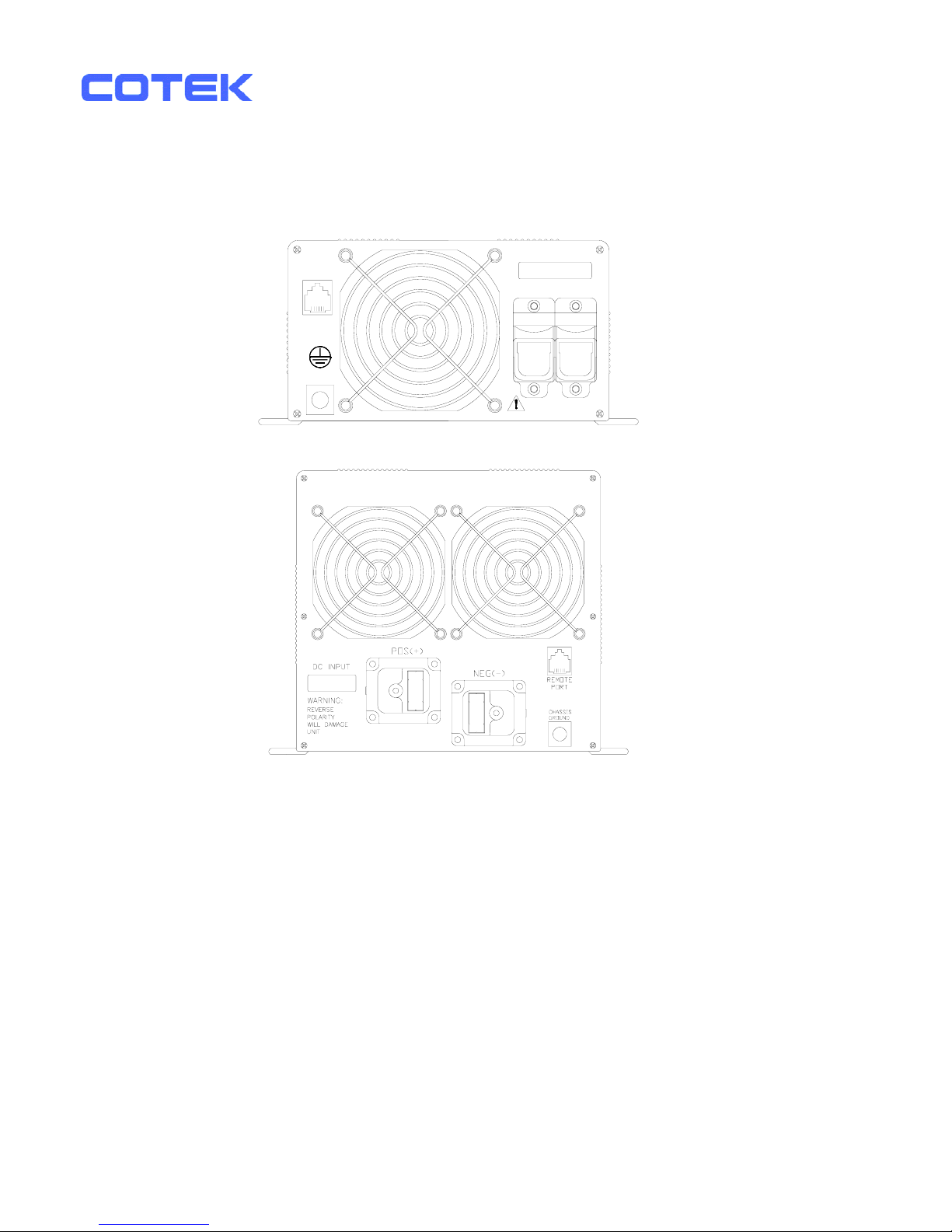
3-2. Rear Panel Operations:
DC INPUT
NEG(-)POS(+)
REVERSE POLARITY
WILL DAMAGE UNIT
CHASSIS
GROUND
PORT
REMOTE
SK700
SK1000
SK1500
SK2000
SK3000
3-2-1. Remote Port:
The SK Series Inverter is compatible with any of the remote controllers,
CR-6, CR-7 or CR-8.
Before using the remote unit, you need to ensure the main switch is in
the “ REMOTE” position and the input voltage of the power inverter is
the same as it of the remote unit.
3-2-2. Fan Ventilation:
Be sure to keep it a distance (at least 1 inch) form surrounding things.
14
Page 20
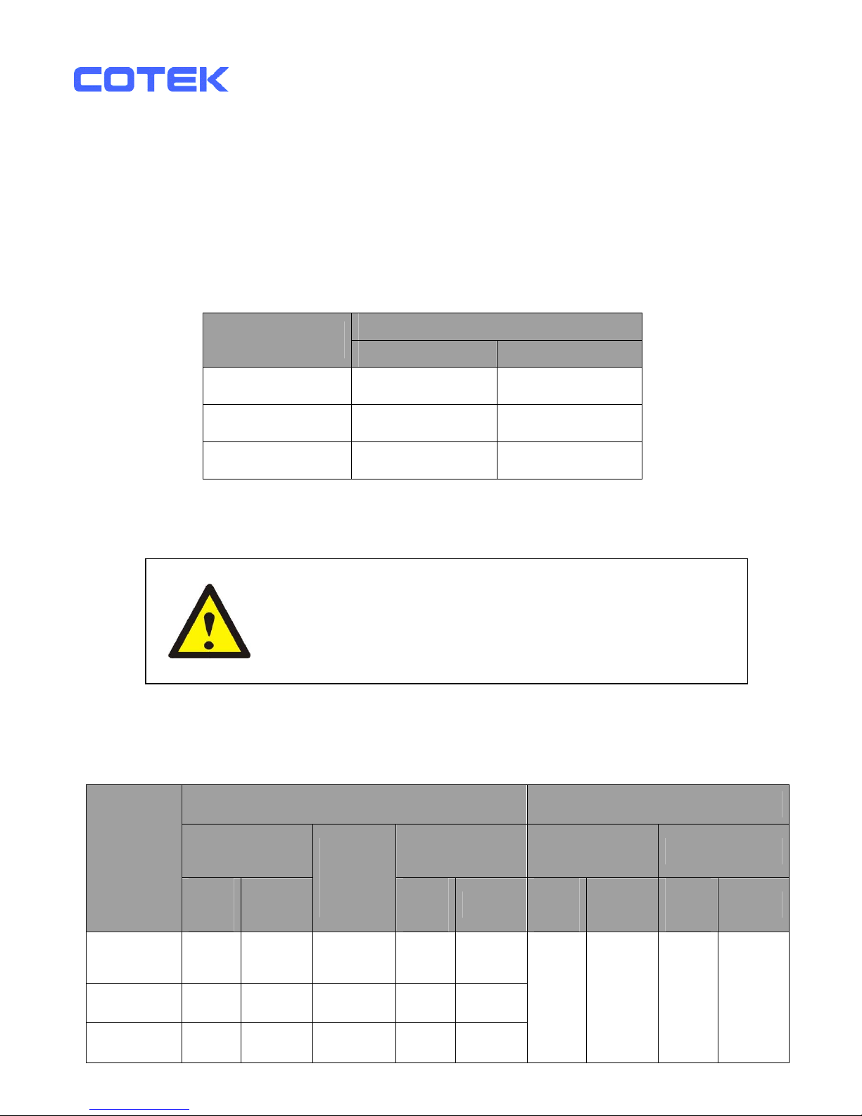
3-2-3. DC Input Terminal:
Connect DC input terminal to 12V / 24V / 48V battery or the other
power sources.
【+】represents positive, and【-】represents negative. Reverse
polarity connection will blow the internal fuse and may damage the
inverter permanently.
DC Input Voltage
Model
Minimum Maximum
12 V 10.5 15.0
24 V 21.0 30.0
48 V 42.0 60.0
3-2-4. Use wire # 8 AWG to connect Chassis ground with vehicle chassis.
WARNING!
Operating the inverter without a proper ground
Connection may cause an electrical hazard.
3-3. Protections Features:
DC Input (VDC) Over Temperature Protection
Over Voltage
Under
Voltage
INTERIOR HEAT SINK
Model
Shutdown
Restart
Under
Voltage
Alarm
Shutdown
Restart
Shutdown
Restart
Shutdown
Restart
12 V 15.3 14.2 11.0 10.5 12.5
24 V 30.6 28.4 22.0 21.0 25.0
48V
61.2 56.8 44.0 42.0 50.0
70℃ 45℃
90℃ 60℃
15
Page 21
3-4. Installation:
The power inverter should be installed in an environment that meets the
following requirements:
3-4-1. Dry – Do not allow water to drip on or enter into the inverter.
3-4-2. Cool – Ambient air temperature should be between 0℃ and 40℃, the
cooler the better.
3-4-3. Safe – Do not install the inverter in a battery compartment or other
areas where flammable fumes may exist, such as fuel storage areas or
engine compartments.
3-4-4. Ventilated –Keep the inverter a distance (as least 1 inch) away from
surrounding things. Ensure the ventilation shafts on the rear and the
bottom of the unit are not obstructed.
3-4-5. Dust – Do not install the Inverter in a dusty environments
The dust can be inhaled into the unit when the cooling fan is working.
3-4-6. Close to batteries – Avoid excessive cable lengths. Do not install the
Inverter in the same compartment as batteries.
Use the recommended wire lengths and sizes (see section 3-5).
Do not mount the Inverter where it will be exposed to the gases
produced by the battery. These gases are very corrosive, and
prolonged exposure will damage the Inverter.
WARNING!
Shock Hazard. Before proceeding further, carefully
check that the Inverter is NOT connected to any
batteries, and that all wiring is disconnected from any
electrical sources. Do not connect the output terminals
of the Inverter to an incoming AC source.
16
Page 22
3-5. DC Wiring Connections:
Follow this procedure to connect the battery cables to the DC input terminals
of the Inverter. The cables should be as short as possible (less than 10 feet
/ 3 meters ideally) and large enough to handle the required current in
accordance with the electrical codes or regulations applicable to the
installation.
Cables that are not an adequate gauge (too narrow) or too long will
deteriorate inverter performance such as poor surge capability and frequent
low-input voltage warnings and shutdowns.
These low input voltage warnings are due to DC voltage drop across the
cables from the inverter to the batteries.
The longer and narrower the cables, the greater the voltage drop.
Increasing DC cable size helps improve the situation.
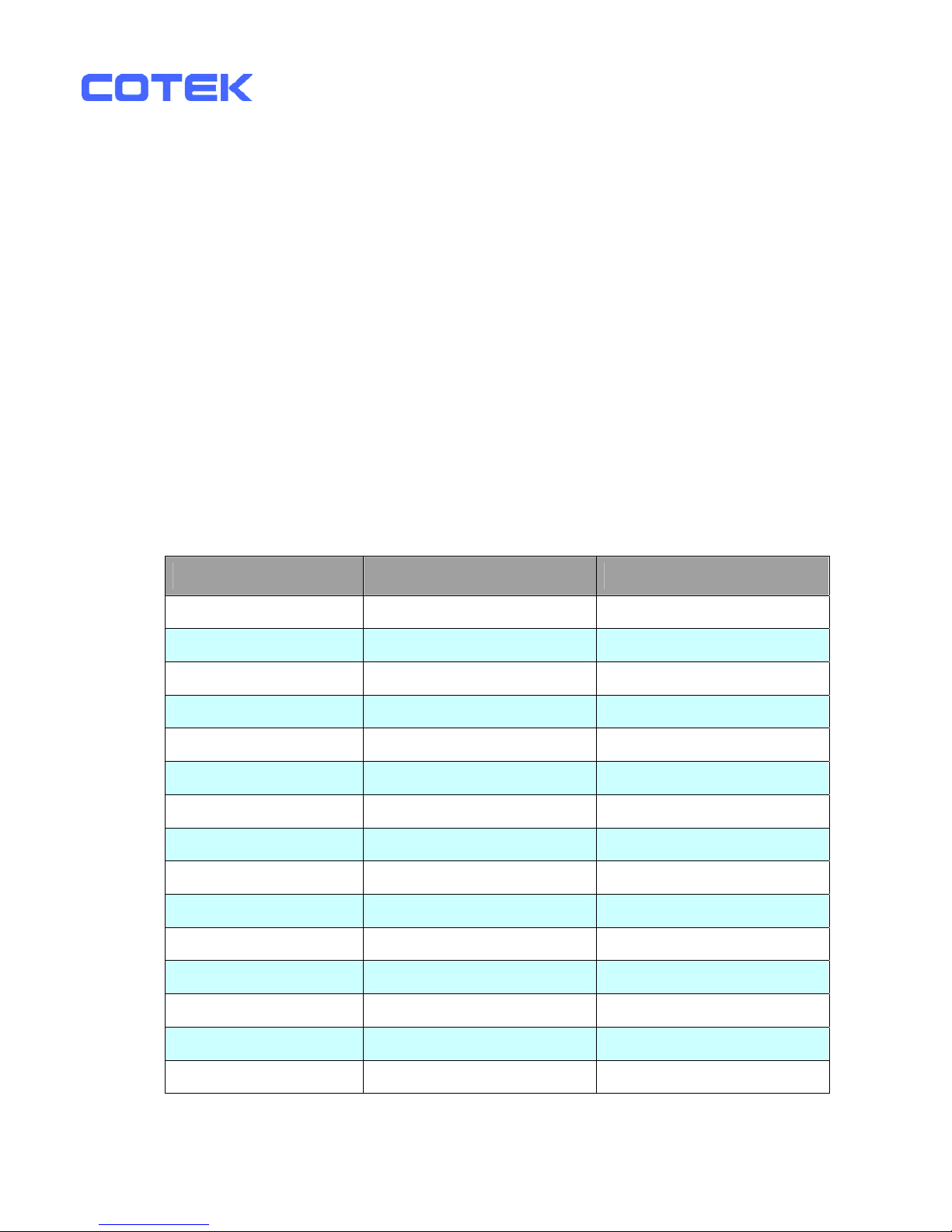
COTEK recommends the following cables for optimum inverter performance.
(Apply both 120V and 230V versions )
Model No Wire AWG Inline Fuse
SK700-112 / 212 # 4 100 A
SK700-124 / 224 # 6 50 A
SK700-148 / 248 # 8 30 A
SK1000-112 / 212 # 2 150 A
SK1000-124 / 224 # 4 80 A
SK1000-148 / 248 # 6 40 A
SK1500-112 / 212 # 2 200 A
SK1500-124 / 224 # 4 100 A
SK1500-148 / 248 # 6 50 A
SK2000-112 / 212 # 2/0 250 A
SK2000-124 / 224 # 1/0 125 A
SK2000-148 / 248 # 2 70 A
SK3000-112 / 212 # 4/0 400 A
SK3000-124 / 224 # 2/0 200 A
SK3000-148 / 248 # 1/0 100 A
17
Page 23
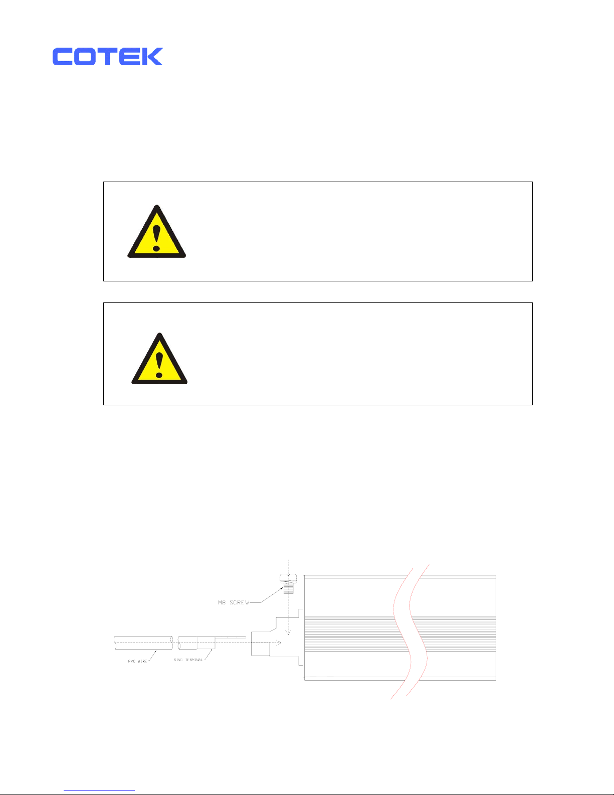
3-5-1. Connect the cables to the power input terminals on the rear panel of
the inverter. The red terminal is represents positive (+) and black
terminal represents negative (-). Insert the cables into the terminals
and tighten the screw to clamp the wires securely.
Also, use only high quality copper wire and keep cable length short, a
maximum of 3 - 6 feet.
WARNING!
The installation of a fuse must be on a positive cable.
Failure to place a fuse on “+” cables running between
the inverter and battery may cause damage to the
inverter and will void warranty.
WARNING!
Ensure all the DC connections are tight (torque
to 9 – 10 ft-lbs, 11.7 – 13 Nm). Loose connections
may cause overheat and fire.
AWG#2 - #6
Battery to inverter cable connection
Do not place anything between
battery cable lug and terminal surface.
Assemble exactly as shown.
18
Page 24
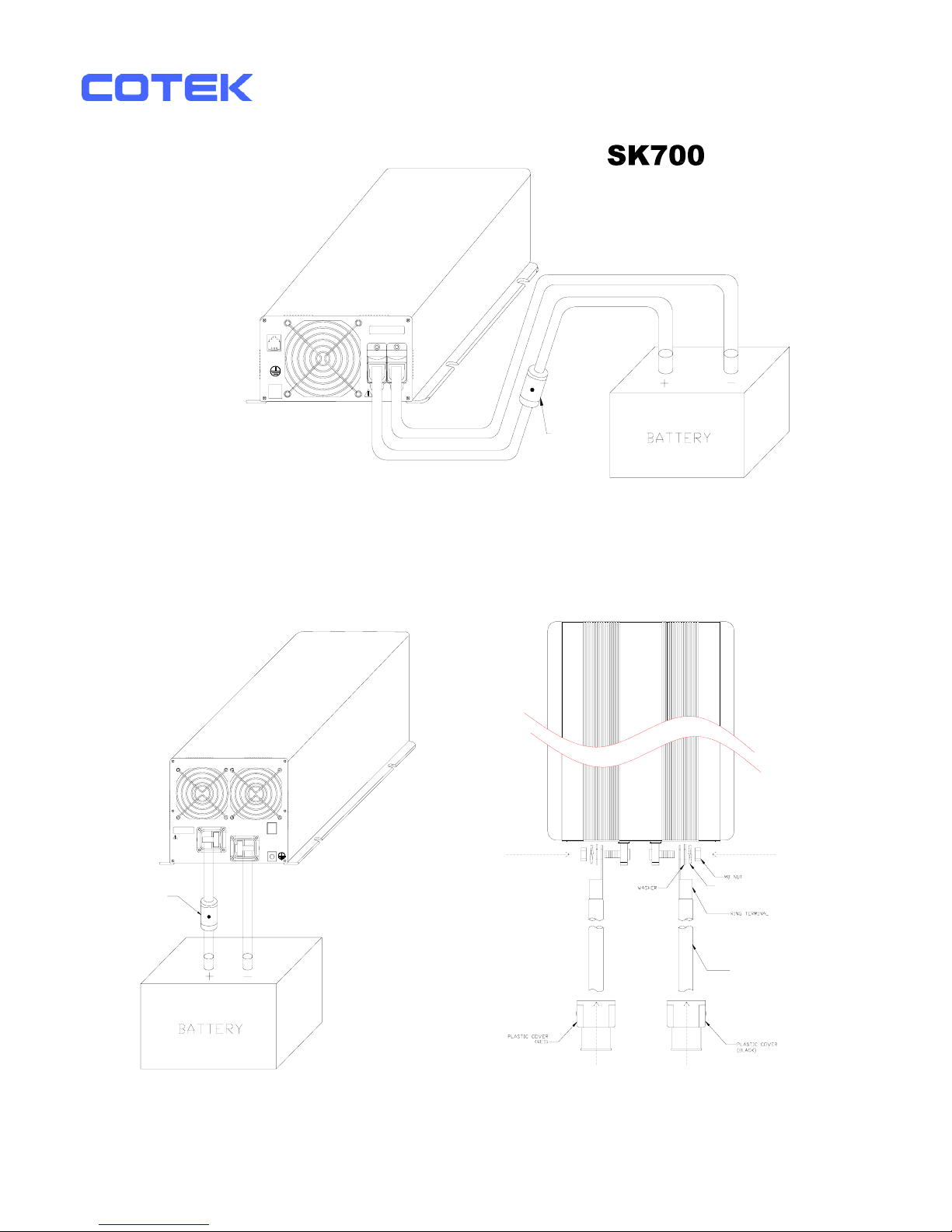
PORT
CHASSIS
GROUND
REMOTE
NEG(-)POS(+)
DC INPUT
INLINE FUSE
SK1000
SK1500
SK2000
SK3000
INLINE FUSE
REVERSE POLARITY
WILL DAMAGE UNIT
SHOCK HAZARD.
DO NOT OPEN. NO
USER SERVICEABLE
PARTS INSIDE.
WARNING:
DC INPUT
POS(+)
CHASSIS
GROUND
NEG(-)
REMOTE
PORT
PVC W I RE
SPRING WASHER
Battery to inverter cable connection
Do not place anything between
battery cable lug and terminal surface.
Assemble exactly as shown.
19
Page 25

3-6. AC Safety Grounding:
The AC output ground wire should go to the grounding point for your loads
( for example, a distribution panel ground bus ).
3-6-1. Neutral Grounding (GFCI’S):
3-6-1-1. 120V models:The neutral conductor of the AC output circuit
of the Inverter is automatically connected to the safety
ground during inverter operation. This conforms to National
Electrical Code requirements that separately derived from AC
sources (such as inverters and generators) which have their
neutral conductors tied to ground in the same way as the
neutral conductors from the utility tied to ground at the AC
breaker panel. For models configured with a transfer relay,
while AC utility power is present and the Inverter is in bypass
mode, this connection (the neutral of the Inverter’s AC output
to input safety ground) is not present so that the utility
neutral is only connected to ground at your breaker panel,
as required.
Ground Fault Circuit Interrupters (GFCI):
Installations in Recreational Vehicles (for North American approvals) will
require GFCI protection of all branch circuit connected to the AC output of
the hardwire terminal equipped with Inverter. In addition, electrical codes
require GFCI protection of certain receptacles in residential installations.
While the pure sine wave output of the Inverter is equivalent to the
waveform provided by utilities, compliance with UL standards requires us to
test and recommend specific GFCI.
Cotek has tested the following GFCI – protected 20A receptacles and found
that they functioned properly when connected to the output of the Inverter.
20
Page 26

3-7. Inverter Operation:
To operate the power inverter, use the ON / OFF switch on the Front panel to
turn the power on. Then the power inverter is ready to deliver AC power to
your loads. If there is several loads use, turn them on separately after the
inverter is “ON” in order to prevent OVP resulted from the surge power.
3-7-1. Set the power switch to “ON” position and the buzzer will send out
“Beep” sounds at the moment. Then the inverter will make selfdiagnosis, and the LED’s indicators will also appear various colors.
Finally the buzzer will “Beep” again and the Input Level and Status
LED indicators will turn to “Green” color, then the inverter starts to
work successfully.
3-7-2. Set the power switch to the OFF position, then the inverter stops and
all the lights go Off.
3-7-3. Set the power inverter switch to ON position and turn the test load On.
The inverter should supply power to the load. If you plan to
accurately measure the true output r.m.s. voltage of the inverter, a
meter such as FLUKE 45 BECKMAN 4410 or TRIPLETT 4200 must be
used.
21
Page 27
4. Troubleshooting:
WARNING!
Do not open or disassemble the Inverter.
Attempting to service the unit yourself may cause the
risk of electrical shock or fire.
Problems and Symptoms Possible Cause Solutions
“No AC Power Output”
STATUS illuminates the red LED
a. Blinking fast Over input voltage.
( OVP )
Check input voltage.
Reduce input voltage.
b. Blinking slowly. Low input voltage.
( UVP )
Recharge battery.
Check connections
and the cable.
c. Blinking Intermittently. Thermal shutdown.
( OTP )
Improve ventilation.
Make sure ventilation
shafts in the inverter
are not obstructed.
Lower ambient
temperature.
d. Solid ON. Short circuit or Wiring
error.
Overload.(OLP)
Check AC wiring for
short circuit.
Reduce the load.
22
Page 28

5. Maintenance:
To keep your inverter operating properly, there is very little maintenance required.
You should clean the exterior periodically with a damp cloth to prevent
accumulation of dust and dirt. At the same time, tighten the screws on the DC
input terminals.
6. Warranty:
We guarantee this product against defects in materials and workmanship for a
period of 24 months from the date of purchase and will repair or replace any
defective power inverters if you directly returned them to us with postage paid.
Please note that Cotek is only responsible for ensuring our products are
operational before delivering. This warranty will be considered void if the unit has
been misused, altered, or accidentally damaged. Cotek is not liable for anything
that occurs as a result of the user’s fault.
23
Page 29

No. 33, Rong Hsin Rd., Pa Teh City, Tao Yuan County, Taiwan
Phone:886-3-3661581 FAX:886-3-3676029
E-mail:
[email protected] http:// www.cotek.com.tw
 Loading...