

Page 1
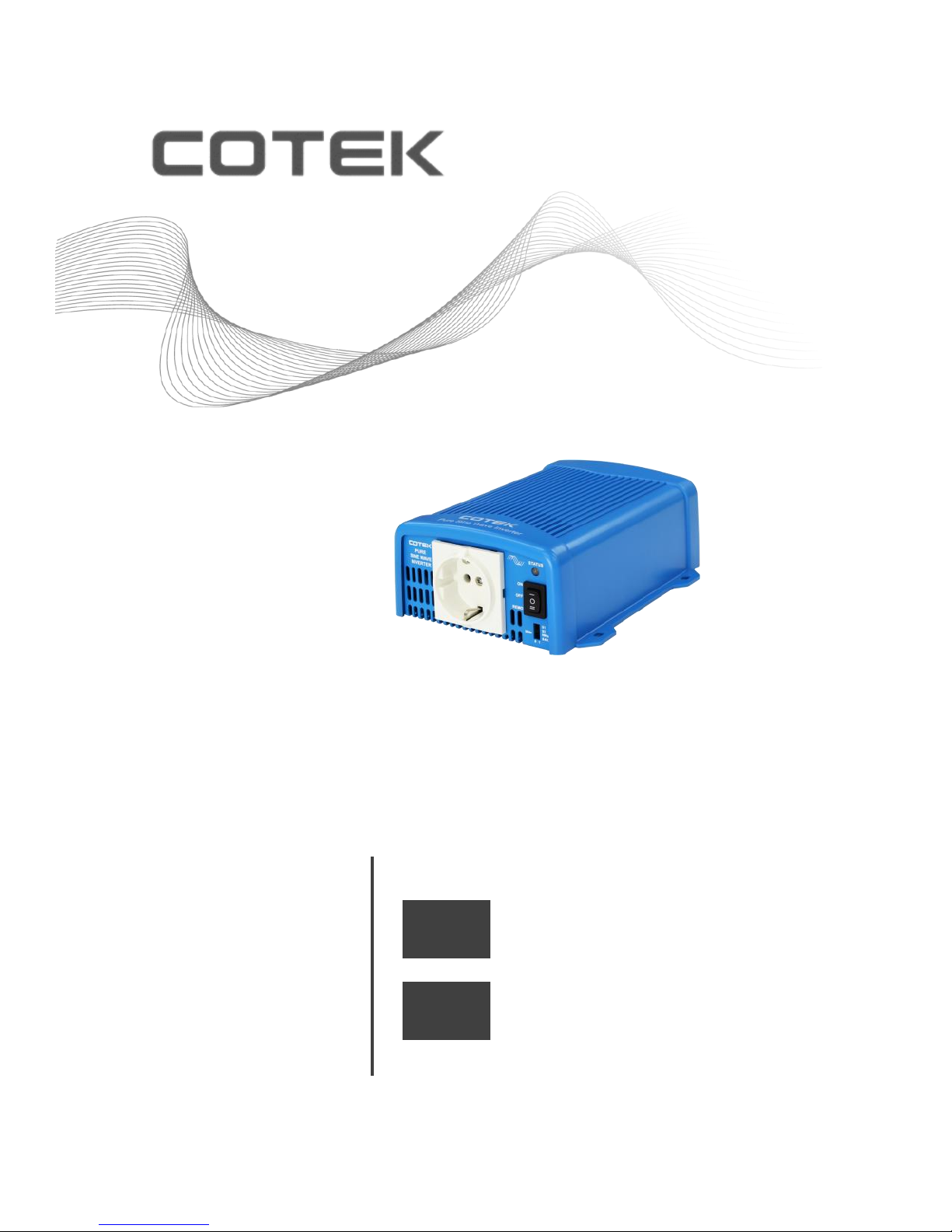
SE Series User’s Manual
SE200 SE350 SE400
PURE SINE WAVE INVERTER
EN
[Page 1]
SE200 SE350 SE400
Onduleurs pur sinus
FR
[Page 17]
FR
[Page 26]
Page 2

Legal Provisions
Copyrights 2017 COTEK Electronic IND. CO. All Rights Reserved.
Any part of this document may not be reproduced in any form for any purpose without the prior
written permission of COTEK Electronic IND. CO. For the conditions of the permission to use
this manual for publication, contact COTEK Electronic IND. CO., LTD. In all related COTEK
product activities, Neither COTEK Electronic IND. CO., LTD. nor its distributors or dealers be
liable to anyone for indirect, incidental, or consequential damages under any circumstances.
Specifications are subject to change without notice. Every attempt has been made to make this
document complete, accurate and up-to-date. COTEK Electronic IND. CO., LTD reserve the
right to make changes without notice and shall not be responsible for any damages, including
indirect, incidental or consequential damages, caused by reliance on the material presented,
including, but not limited to, omissions, typographical errors, arithmetical errors or listing errors
in the content material. All trademarks are recognized even if these are not marked separately.
Missing designations do not mean that a product or brand is not a registered trademark.
Page 3

EN
Table of Content
1. SAFETY INSTRUCTIONS 1
1-1. General Safety Precautions 1
1-2. Other Safety Notes 2
2. FUNCTIONAL CHARACTERISTICS INTRODUCTION 3
2-1. System 3
2-2. Block Diagram 3
2-3. Electrical Specification 4
2-3-1. SE200 Specification 4
2-3-2. SE350 Specification 5
2-3-3. SE400 Specification 7
2-4. Mechanical Drawings 11
3. INSTALLATION AND MAINTENANCE 12
3-1. Front Panel Introduction 12
3-1-1. ON / OFF / Remote Main Switch 12
3-1-2. LED Indicator 12
3-1-3. AC Output 14
3-1-4. Function Switch 15
3-2. Rear Panel Introduction 16
3-2-1. DC Input Terminal 16
3-2-2. Green Terminal 17
3-2-3. Remote Port (RJ-11) 18
3-2-4. Chassis ground 19
3-3. Maintenance 19
3-4. Inverter Installation and Operation 19
Page 4

EN
4. OPERATION 21
4-1. Connecting the DC Cable 21
4-2. Connecting the Input Power 21
4-3. Connecting the Loads 21
4-4. Switch ON Inverter 22
4-5. Protection Mechanism 22
4-5-1. SE200 Protection Mechanism 22
4-5-2. SE350 protection mechanism 22
4-5-3. SE400 Protection Mechanism 23
4-6. Troubleshooting Guide 23
5. WARRANTY 25
5-1 Warning 25
5-2 Warranty 25
Page 5

1
1. Safety Instructions
1-1. General Safety Precautions
Warning! Before using the Inverter, read the safety
instructions.
Do not expose the inverter to rain, snow, spray or dust. To reduce
the risk of fire hazard, do not cover or obstruct the ventilation
openings and do not install the inverter in a zero-clearance
compartment.
To avoid the risk of fire and electric shock, make sure that the
existing wiring is in good electrical condition, and the wire size is
not undersized.
This equipment contains components which can produce arcs or
sparks. To prevent fire or explosion do not install in compartment
containing batteries or flammable materials or in location which
require ignition protected equipment. This includes any space
containing gasoline-powered machinery, fuel tanks, or joints,
fittings, or other connection between components of the fuel
system.
Depending on the user scenario, the AC output of the inverter
may require user installed breaker or fuse. In AC output hardwire
application, AC socket will not been provided. The inverter
incorporates standard AC short circuit protection.
An over current protection at the time of installation shall be
provided by others for the AC output circuit.
Additional breakers suitable for 20A(SE200 & SE350) /
10A(SE400) branch circuit protection shall be provided for the
GFCI receptacles.
The following precautions should be taken when working on the
inverter:
Step 1 Remove watches, rings, or other metal objects
Step 2 Use tools with insulated handles
Step 3 Wear rubber gloves and boots
Page 6

2
EN
1-2. Other Safety Notes
Upon receipt, examine the carton box for damage. If you have
found any damage on the carton box please notify the company
you purchased this unit from.
Do not operate near water or in excessive humidity.
Do not open or disassemble the inverter, and warranty may be
voided.
The DC side connections should be firm and tight.
Grounding: Reliable grounding should be maintained.
Do not drop a metal tool on the battery. The resulting spark or
short-circuit on the battery or on the other electrical part may
cause an explosion.
Install the inverter in a well-ventilated area. Do not block the air
vents at the front AC output side, or the air exhausts at the rear
DC input side.
Wiring: Adequate input power must be supplied to the inverter for
proper use; correct wiring sizes must be ensured.
Mount the inverter such that the fan axis is horizontal.
Do not operate the inverter close to combustible gas or open fire.
Do not operate appliances that may feed power back into the
inverter.
The inverter should be operated in an ambient temperature
range:-20℃ to 60℃.
Otherwise the output efficiency may be affected. Air flow to the
inverter must not be blocked.
Page 7
3
2. Functional Characteristics Introduction
2-1. System
The unit is a highly reliable DC-AC inverter system, designed with
advanced power electronic and microprocessor technology offering
the following features:
Pure sine wave output waveform:
SE200:THD < 3 % / SE350:THD < 3 % / SE400:THD < 5 %
Intelligent software for power management
Loading and temperature controlled cooling fan
CR-8 remote management and control
Dry contact terminal
Advanced protection features
Input protection
Over/Under voltage protection
Reverse polarity protection (Fuse)
Output protection
Overload protection
Over temperature protection
Short circuit protection
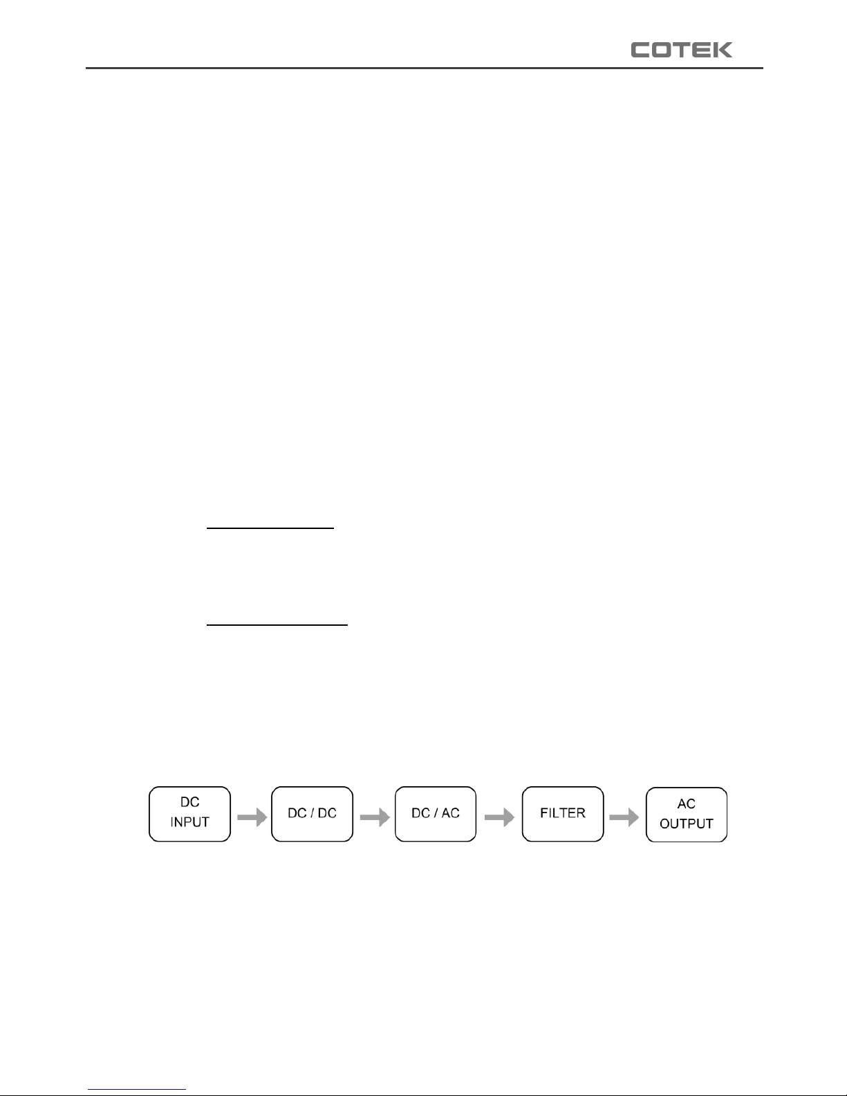
2-2. Block Diagram
Page 8
4
EN
2-3. Electrical Specification
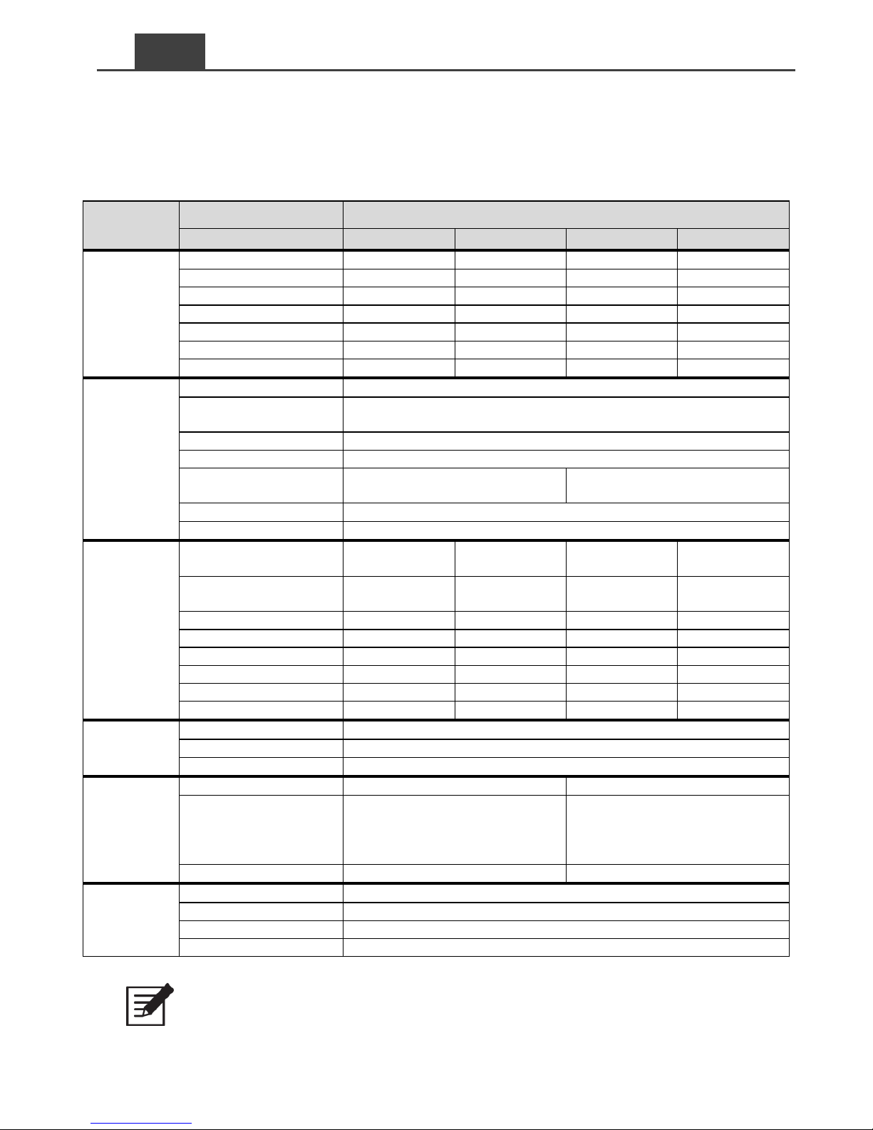
2-3-1. SE200 Specification
Electrical
Specification
Model No.
Item
SE200-112
SE200-124
SE200-212
SE200-224
Input
Voltage
12VDC
24VDC
12VDC
24VDC
Voltage Range
10.0~16.0VDC
20.0~32.0VDC
10.0~16.0VDC
20.0~32.0VDC
No Load Current
< 0.5A
< 0.4A
< 0.5A
< 0.4A
Power Saving Mode
< 0.12A
< 0.06A
< 0.12A
< 0.06A
Efficiency (Typ.)
89%
91%
91%
93%
On Mode @ Save Mode
< 0.12A
< 0.06A
< 0.12A
< 0.06A
On Mode @ No Load Mode
< 0.5A
< 0.4A
< 0.5A
< 0.4A
Output
Continuous Output Power
200 W
Over Rated Power
(3 Min.)
230 W
Peak Power (3 Sec.)
250 W
Frequency
50 / 60 Hz ± 0.5% (Dip Switch Selectable)
Output Voltage
100 / 110 / 115 / 120 VAC ± 5%
(Dip Switch Selectable)
200 / 220 / 230 / 240 VAC ± 5%
(Dip Switch Selectable)
Short-Circuit Protection
2 seconds and restart 3 times shutdown
Output Waveform
Pure Sine Wave (THD < 3%@ Normal Load)
Protection
Input Over-Voltage
Protection
16.0VDC ± 3%
32.0VDC ± 3%
16.0VDC ± 3%
32.0VDC ± 3%
Input Under-Voltage
Protection
10.0VDC ± 3%
20.0VDC ± 3%
10.0VDC ± 3%
20.0VDC ± 3%
BAT. Low Shutdown
10.0VDC ± 3%
20.0VDC ± 3%
10.0VDC ± 3%
20.0VDC ± 3%
BAT. Low Alarm
10.5VDC ± 3%
21.0VDC ± 3%
10.5VDC ± 3%
21.0VDC ± 3%
BAT. Low Restart
12.5VDC ± 3%
25.0VDC ± 3%
12.5VDC ± 3%
25.0VDC ± 3%
BAT. High Alarm
15.5VDC ± 3%
31.0VDC ± 3%
15.5VDC ± 3%
31.0VDC ± 3%
BAT. High Shutdown
16.0VDC ± 3%
32.0VDC ± 3%
16.0VDC ± 3%
32.0VDC ± 3%
BAT. High Restart
14.5VDC ± 3%
29.0VDC ± 3%
14.5VDC ± 3%
29.0VDC ± 3%
Environment
Working Temp.
-20 ℃~60 ℃
Storage Temp.
-30 ℃~70 ℃
Working Humidity
10~95% RH, non-condensing
Safety &
EMC
Safety Standards
----
Certified EN 60950-1
EMC standards
Certified FCC class B
Certified EN55022; EN61204-3
EN61000-6-1, 6-3
EN61000-3-2, -3-3; EN55024
EN61000-4-2, 3, 4, 5, 6, 8, 11
E-mark
----
Certified CISPR 25; ISO 7637-2
Others
Dimension(WxHxD)
150 mm X 68mm X187 mm
Weight
1.6kg
Remote Control
CR-8 (optional)
Cooling
Temperature & Load Controlled cooling Fan
Table 1. SE200 specification
Note:
This test condition is normal DC input and temperature 25℃
Page 9
5
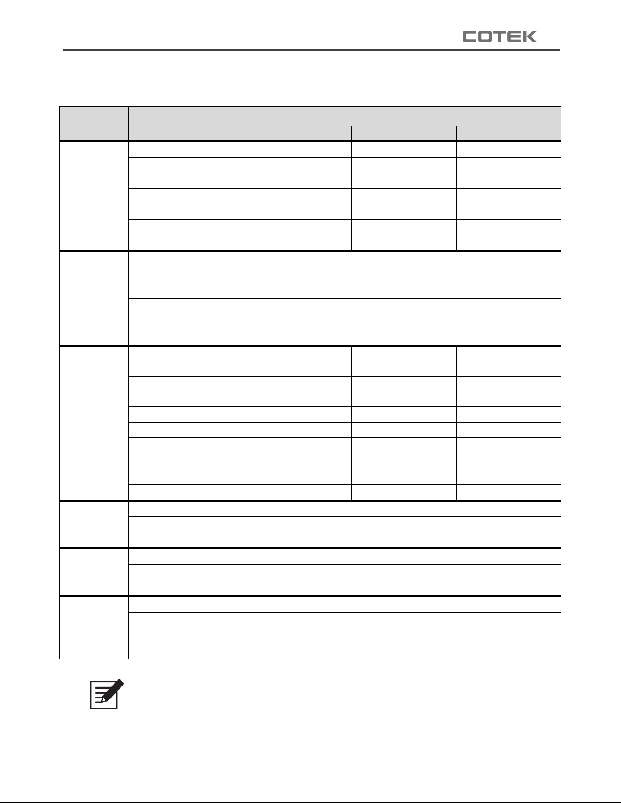
2-3-2. SE350 Specification
Electrical
Specification
Model No.
Item
SE350-112
SE350-124
SE350-148
Input
Voltage
12VDC
24VDC
48VDC
Voltage Range
10.0~15.5VDC
20.0~31.0VDC
40.0~62.0VDC
No Load Current
< 0.65A
< 0.32A
< 0.16A
Power Saving Mode
< 90mA
< 60mA
< 40mA
Efficiency (Typ.)
87%
88%
89%
On Mode @ Save Mode
< 90mA
< 60mA
< 40mA
On Mode @ No Load Mode
< 0.65A
< 0.32A
< 0.16A
Output
Continuous Output Power
350 W
Surge Power
700 W
Frequency
50 / 60 Hz ± 0.1% (Dip Switch Selectable)
Output Voltage
100 / 110 / 115 / 120 VAC ± 5% (Dip Switch Selectable)
Short-Circuit Protection
2 seconds and restart 4 times shutdown
Output Waveform
Pure Sine Wave (THD < 3%@ Normal Load)
Protection
Input Over-Voltage
Protection
15.5V ± 0.25V
31.0V ± 0.5V
62.0V ± 1V
Input Under-Voltage
Protection
10.0V ± 0.25V
20.0V ± 0.5V
40.0V ± 1V
BAT. Low Shutdown
10.0V ± 0.25V
20.0V ± 0.5V
40.0V ± 1V
BAT. Low Alarm
10.5V ± 0.25V
21.0V ± 0.5V
42.0V ± 1V
BAT. Low Restart
12.0V ± 0.25V
24.0V ± 0.5V
48.0V ± 1V
BAT. High Alarm
15.0V ± 0.25V
30.0V ± 0.5V
60.0V ± 1V
BAT. High Shutdown
15.5V ± 0.25V
31.0V ± 0.5V
62.0V ± 1V
BAT. High Restart
14.5V ± 0.25V
29.0V ± 0.5V
58.0V ± 1V
Environment
Working Temp.
Note
-20 ℃~60 ℃
Storage Temp.
-30 ℃~70 ℃
Working Humidity
90% RH, non-condensing
Safety &
EMC
Safety Standards
----
EMC standards
----
E-mark
----
Others
Dimension(WxHxD)
150 mm X 68mm X187 mm
Weight
1.6kg
Remote Control
CR-8 (optional)
Cooling
Temperature & Load Controlled cooling Fan
Table 2. SE350 for output 100/110/115/120 VAC specification
Note:
Temperature performance:Please refer to Figure 1
Page 10
6
EN
Electrical
Specification
Model No.
Item
SE350-212
SE350-224
SE350-248
Input
Voltage
12VDC
24VDC
48VDC
Voltage Range
10.0~15.5VDC
20.0~31.0VDC
40.0~62.0VDC
No Load Current
< 0.9A
< 0.5A
< 0.25A
Power Saving Mode
< 90mA
< 60mA
< 40mA
Efficiency (Typ.)
89%
90%
91%
On Mode @ Save Mode
< 90mA
< 60mA
< 40mA
On Mode @ No Load Mode
< 0.9A
< 0.5A
< 0.25A
Output
Continuous Output Power
350 W
Surge Power
700 W
Frequency
50 / 60 Hz ± 0.1% (Dip Switch Selectable)
Output Voltage
200 / 220 / 230 / 240 VAC ± 5% (Dip Switch Selectable)
Short-Circuit Protection
2 seconds and restart 4 times shutdown
Output Waveform
Pure Sine Wave (THD < 3%@ Normal Load)
Protection
Input Over-Voltage
Protection
15.5V ± 0.25V
31.0V ± 0.5V
62.0V ± 1V
Input Under-Voltage
Protection
10.0V ± 0.25V
20.0V ± 0.5V
40.0V ± 1V
BAT. Low Shutdown
10.0V ± 0.25V
20.0V ± 0.5V
40.0V ± 1V
BAT. Low Alarm
10.5V ± 0.25V
21.0V ± 0.5V
42.0V ± 1V
BAT. Low Restart
12.0V ± 0.25V
24.0V ± 0.5V
48.0V ± 1V
BAT. High Alarm
15.0V ± 0.25V
30.0V ± 0.5V
60.0V ± 1V
BAT. High Shutdown
15.5V ± 0.25V
31.0V ± 0.5V
62.0V ± 1V
BAT. High Restart
14.5V ± 0.25V
29.0V ± 0.5V
58.0V ± 1V
Environment
Working Temp.
Note
-20 ℃~60 ℃
Storage Temp.
-30 ℃~70 ℃
Working Humidity
90% RH, non-condensing
Safety &
EMC
Safety Standards
Certified EN 60950-1
EMC standards
Certified EN55022 class B, EN 55024; EN61204-3
EN61000-3-2, -3-3; EN 61000-6-1, -6-3
IEC 61000-4-2, 3, 4, 5, 6, 8, 11
E-mark
Certified CISPR 25; ISO 7637-2
Others
Dimension(WxHxD)
150 mm X 68mm X187 mm
Weight
1.6kg
Remote Control
CR-8 (optional)
Cooling
Temperature & Load Controlled cooling Fan
Table 3. SE350 for output 200/220/230/240 VAC specification
Note:
Temperature performance:Please refer to Figure 1
Page 11
7
2-3-3. SE400 Specification
Electrical
Specification
Model No.
Item
SE400-112
SE400-124
SE400-148
Input
Voltage
12VDC
24VDC
48VDC
Voltage Range
10.5~16.0VDC
21.0~32.0VDC
42.0~64.0VDC
No Load Current
<1A @12VDC
<0.5A @24VDC
<0.25A @48VDC
Power Saving Mode
<0.2A @12VDC
<0.1A @24VDC
<0.05A @48VDC
Efficiency (Typ.)
88%
89%
90%
On Mode @ Save Mode
<1A @12VDC
<0.5A @24VDC
<0.25A @48VDC
On Mode @ No Load Mode
<0.2A @12VDC
<0.1A @24VDC
<0.05A @48VDC
Output
Continuous Output Power
400 W (± 3%)
Max. Output Power (1Min.)
> 400 W~460 W (100%~115%)
Surge Power (1Sec.)
< 800 W
Frequency
50 / 60 Hz ± 0.5% (Dip Switch Selectable)
Output Voltage
100 / 110 / 115 / 120 VAC ± 5% (Dip Switch Selectable)
Short-Circuit Protection
1 Sec Shutdown
Output Waveform
Pure Sine Wave (THD < 5%@ Normal Load)
Protection
Input Over-Voltage
Protection
16.0 ± 0.3VDC
32.0 ± 0.5VDC
64.0 ± 1.0VDC
Input Under-Voltage
Protection
10.5 ± 0.3VDC
21.0 ± 0.5VDC
42.0 ± 1.0VDC
BAT. Low Shutdown
10.5 ± 0.3VDC
21.0 ± 0.5VDC
42.0 ± 1.0VDC
BAT. Low Alarm
10.5 ± 0.3VDC
21.0 ± 0.5VDC
42.0 ± 1.0VDC
BAT. Low Restart
14.5V± 0.3V
28.0 ± 0.5VDC
56.0 ± 0.5VDC
BAT. High Shutdown
16.0 ± 0.3VDC
32.0 ± 0.3VDC
64.0 ± 0.3VDC
BAT. High Restart
12.5V± 0.3V
25.0V± 0.3V
50.0± 0.3V
Environment
Working Temp.
-20 ℃~40 ℃
Storage Temp.
-30 ℃~70 ℃
Working Humidity
10~95% RH, non-condensing
Safety &
EMC
Safety Standards
Certified UL 458
(UL only for GFCI receptacles)
----
EMC standards
Certified FCC class B
E-mark
----
Others
Dimension(WxHxD)
150 mm X 68mm X187 mm
Weight
1.256kg
Remote Control
CR-8 (optional)
Cooling
Temperature & Load Controlled cooling Fan
Table 4. SE400 for output 100/110/115/120 VAC specification
Note:
Normal load Condition:Vin =12.5V/25V/50V, Vo=100/110/115/120 VAC 80% load
(PF=1.0)
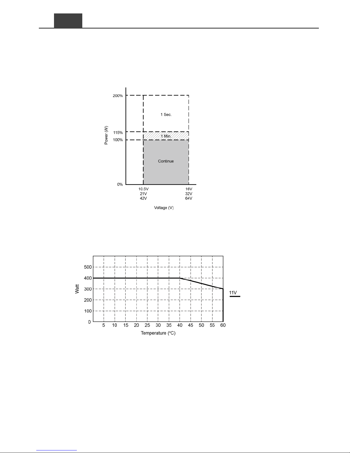
Voltage performance:Please refer to Figure 2
Temperature performance:Please refer to Figure 3
Page 12
8
EN
Electrical
Specification
Model No.
Item
SE400-212
SE400-224
SE400-248
Input
Voltage
12VDC
24VDC
48VDC
Voltage Range
10.5~16.0VDC
21.0~32.0VDC
42.0~64.0VDC
No Load Current
<1A @12VDC
<0.5A @24VDC
<0.25A @48VDC
Power Saving Mode
<0.2A @12VDC
<0.1A @24VDC
<0.05A @48VDC
Efficiency (Typ.)
88%
89%
90%
On Mode @ Save Mode
<1A @12VDC
<0.5A @24VDC
<0.25A @48VDC
On Mode @ No Load Mode
<0.2A @12VDC
<0.1A @24VDC
<0.05A @48VDC
Output
Continuous Output Power
400 W (± 3%)
Max. Output Power (1Min.)
> 400 W~460 W (100%~115%)
Surge Power (1Sec.)
< 800 W
Frequency
50 / 60 Hz ± 0.5% (Dip Switch Selectable)
Output Voltage
200 / 220 / 230 / 240 VAC ± 5% (Dip Switch Selectable)
Short-Circuit Protection
1 Sec Shutdown
Output Waveform
Pure Sine Wave (THD < 5%@ Normal Load)
Protection
Input Over-Voltage
Protection
16.0 ± 0.3VDC
32.0 ± 0.5VDC
64.0 ± 1.0VDC
Input Under-Voltage
Protection
10.5 ± 0.3VDC
21.0 ± 0.5VDC
42.0 ± 1.0VDC
BAT. Low Shutdown
10.5 ± 0.3VDC
21.0 ± 0.5VDC
42.0 ± 1.0VDC
BAT. Low Alarm
10.5 ± 0.3VDC
21.0 ± 0.5VDC
42.0 ± 1.0VDC
BAT. Low Restart
14.5V± 0.3V
28.0 ± 0.5VDC
56.0 ± 0.5VDC
BAT. High Shutdown
16.0 ± 0.3VDC
32.0 ± 0.3VDC
64.0 ± 0.3VDC
BAT. High Restart
12.5V± 0.3V
25.0V± 0.3V
50.0± 0.3V
Environment
Working Temp.
-20 ℃~40 ℃
Storage Temp.
-30 ℃~70 ℃
Working Humidity
10~95% RH, non-condensing
Safety &
EMC
Safety Standards
Certified EN 62368-1
EMC standards
Certified EN55032 class B; EN 55024; EN 61000-3-2, -3-3
IEC61000-4-2, 3, 4, 5, 6, 8, 11
E-mark
Certified CISPR 25; ISO11452-2; ISO 7637-2
Others
Dimension(WxHxD)
150 mm X 68mm X187 mm
Weight
1.256kg
Remote Control
CR-8 (optional)
Cooling
Temperature & Load Controlled cooling Fan
Table 5. SE400 for output 200/220/230/240 VAC specification
Note:
Normal load Condition:Vin =12.5V/25V/50V, Vo=200/220/230/240 VAC 80% load
(PF=1.0)
Voltage performance:Please refer to Figure 2
Temperature performance:Please refer to Figure 3
Page 13
9
2-3-4. SE200 Voltage performance
Figure 1. SE200 temperature performance
2-3-5. SE350 Voltage performance
Figure 2. SE350 temperature performance
Page 14
10
EN
2-3-6. SE400 Voltage & temperature performance
Figure 3. SE400 voltage performance
Figure 4. SE400 temperature performance
Page 15
11
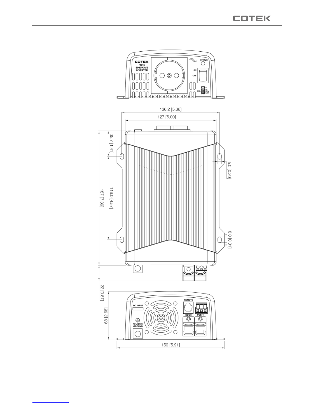
2-4. Mechanical Drawings
Figure 5. SE series mechanical drawings
Page 16
12
EN
3. Installation and Maintenance
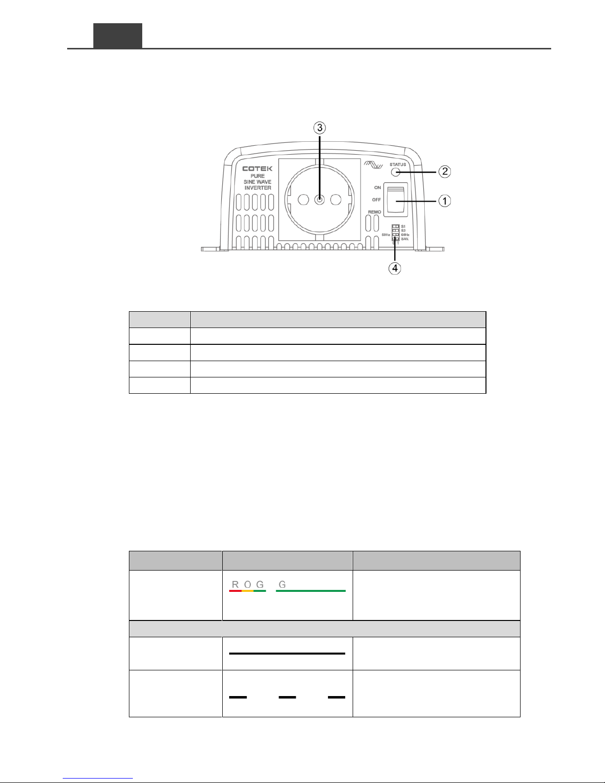
3-1. Front Panel Introduction
Figure 6. SE series front panel view
Model
SESeries Front Panel
ON / OFF / Remote Main Switch
LED Indicator
AC Output
Function Switch
Table 6. SE series front panel introduction
3-1-1. ON / OFF / Remote Main Switch
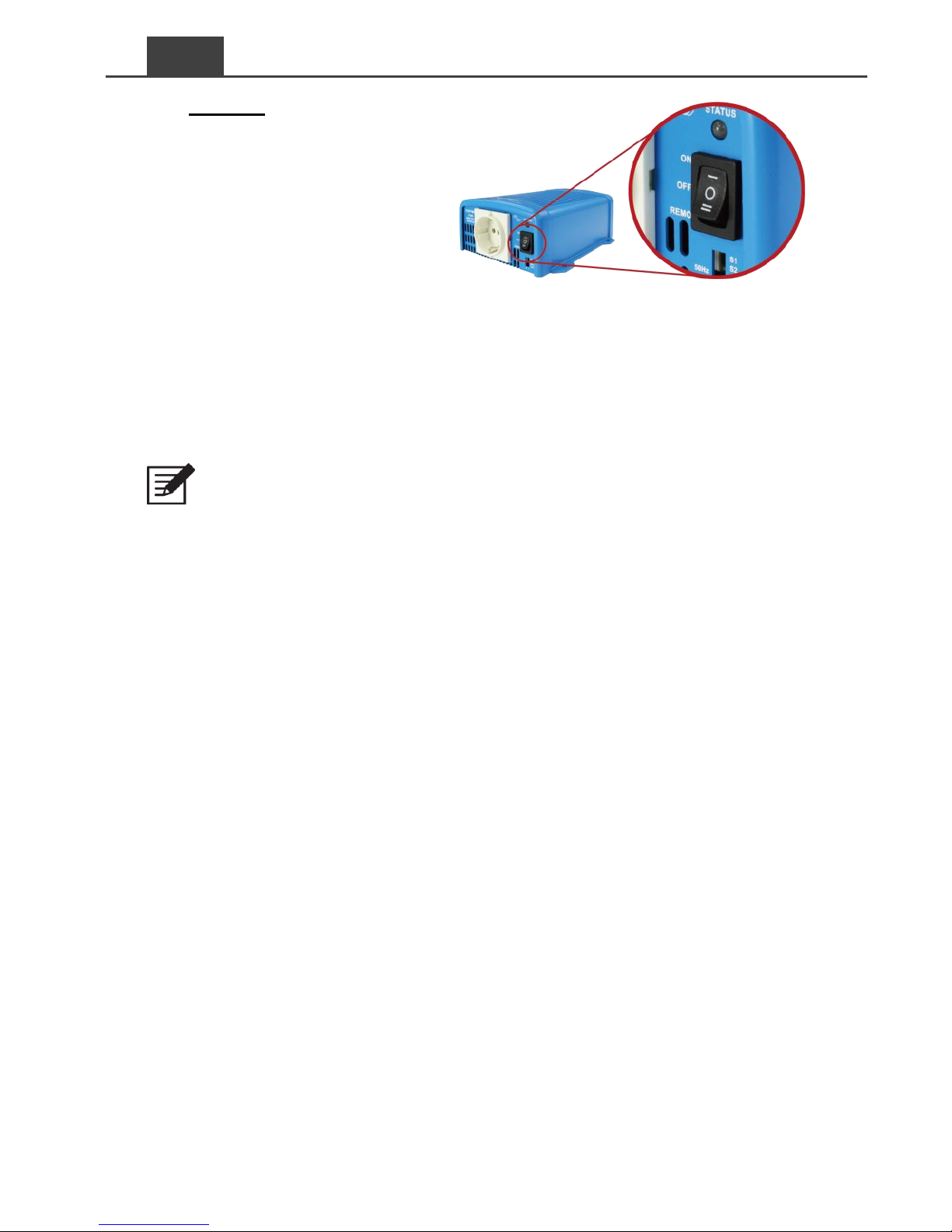
The 3-stage switch is for turning on, turning off and remote mode.
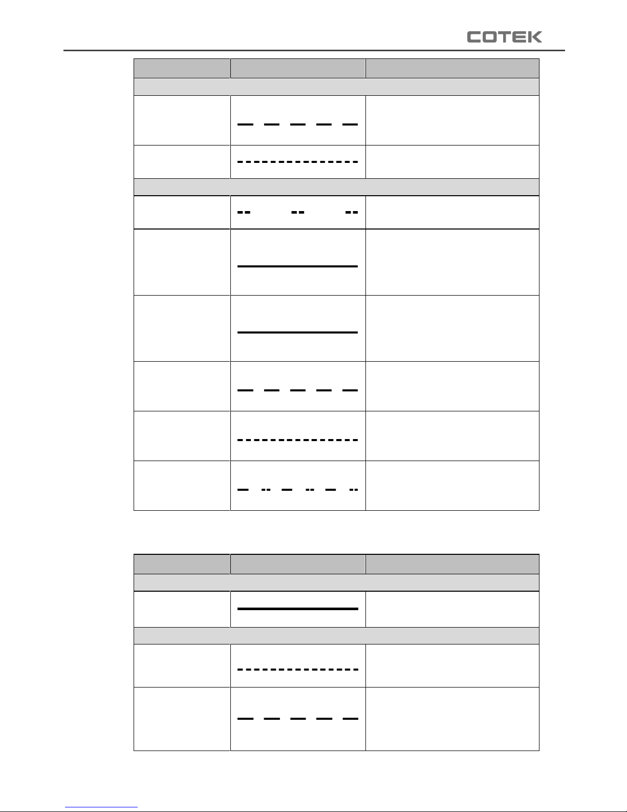
3-1-2. LED Indicator
Inverter status to display fault condition.
SE200 / SE350 LED signal
Status
LED Signal
Description
Power on
R=red, O=orange, R=red
Beep twice, LED shows red
orange green green
Green
Normal
LED lights in solid green
Saving mode
LED flashes green condition in
intermediate condition once
every 2 seconds
Page 17
13
Status
LED Signal
Description
Orange
Under voltage
alarm
LED flashes orange light
slowly with 5 short beeps every
15 seconds
Over voltage
LED flashes orange light every
0.1 seconds
Red
Over
temperature
LED flashes red light quickly
twice every 1.6 seconds
O/P short circuit
LED lights red; following two
short beeps. Inverter shuts
down after two seconds and
restart 3 times.
O/P over load
LED lights red; following two
short beeps. Inverter shuts
down after 3 minutes and
restart 3 times.
Shut down
under voltage
LED flashes red light every 0.4
seconds, then inverter shuts
down.
Shut down over
voltage
LED flashes red light every 0.1
seconds, then inverter shut
down.
Fan alarm
LED flashes red light slowly
once and quickly twice every
1.6 seconds
Table 7. SE200 & SE350 LED status
SE400 LED signal
Status
LED Signal
Description
Green
Normal or
Power ON
LED lights in solid green
Orange
Over load
400W ~ 460W
(100% ~ 115%)
LED fast blink with two long
beeps
Over temp. /
Under temp.
(Heat sink temp. over
80℃ or under -20℃)
LED slow blink
Page 18
14
EN
Status
LED Signal
Description
Red
Over current /
Over load
> 460W (115%)
LED lights in solid red with one
short beeps
Over voltage
(Input DC voltage over
spec.)
LED fast blink
Under voltage
(Input DC voltage
under spec.)
LED slow blink with one long
beeps &two short beeps
Table 8. SE400 LED status
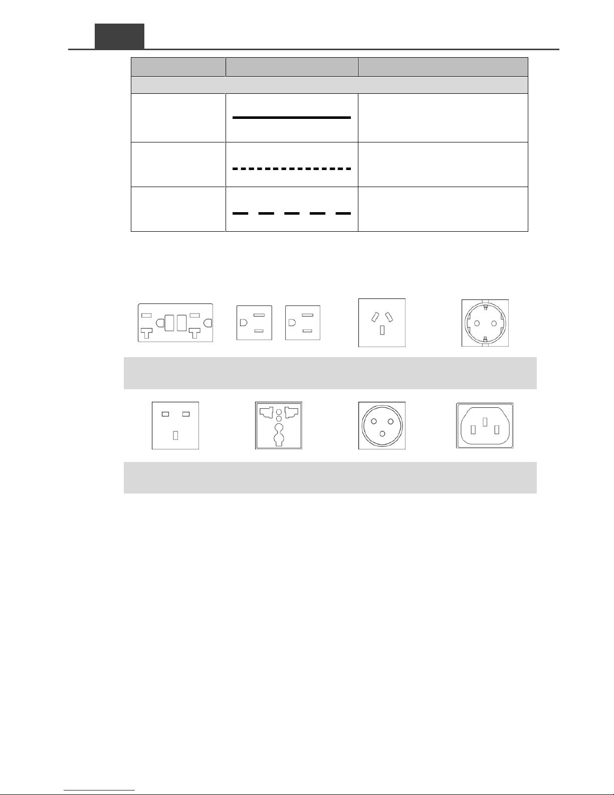
3-1-3. AC Output
North America
(GFCI)
NEMA 5-15R
Australia / New
Zealand
Continental
Europe
United Kingdom
Universal
France Connector
(only SE350)
IEC
(only SE350)
Table 9. SE series AC output
Page 19
15
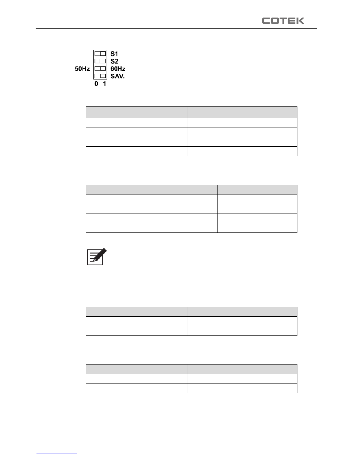
3-1-4. Function Switch
Figure 7. SE series DIP switch
3-1-4-1. Function switch definition
Dip Switch
Function
S1
Voltage select
S2
Voltage select
S3
Frequency Select
S4
Power saving ON/OFF
Table 10. SE series function switch definition
3-1-4-2. Output voltage selection (S1&S2)
Output voltage
S1
S2
100V/200V
0 0 110V/220V
0 1 115V/230V
1 0 120V/240V
1
1
Table 11. SE series output voltage selection
Note:
100V series can be selected between
100/110/115/120VAC, and 200V series can be selected
between 200/220/230/240VAC.
3-1-4-3. Output frequency selection
Frequency
DIP Switch
50Hz
0
60Hz
1
Table 12. SE series output frequency selection
3-1-4-4. Power saving selection
Saving function
DIP Switch
Power Saving OFF
0
Power Saving ON
1
Table 13. SE series power saving selection
Page 20
16
EN
3-1-3-5. Power saving load
Model
Input Saving Power
Saving Wake up
SE200 / SE350
<10VA
>15VA
SE400
<20A
>30 VA
Table 14. SE series power saving load
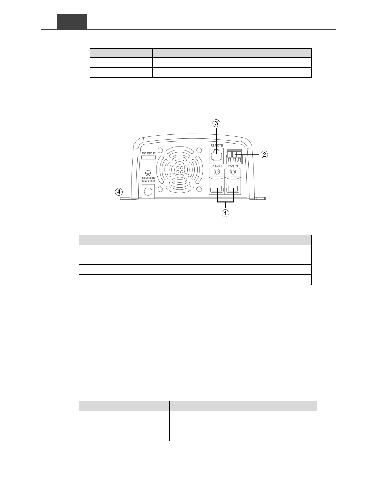
3-2. Rear Panel Introduction
Figure 8. SE series rear panel view
Model
SE Series Rear Panel
DC Input Terminal
Green Terminal
Remote Port (RJ-11)
Chassis Ground
Table 15. SE series rear panel introduction
3-2-1. DC Input Terminal
The DC cables should be as short as possible (less than 6 feet / 1.8
meters ideally)
The size of the cable should be thick enough to limit the voltage
drop to less than 2% when carrying the maximum input current to
prevent frequent low-input voltage warnings, and shutdown.
The following sizes of cables and fuses are recommended distance
(<6 ft.) between the batteries and the inverter.
Model
Wire AWG
Inline fuse
SE200-112 / 212
#10
≧30 A
SE200-124 / 224
#14
≧15 A
SE350-112 / 212
#8
≧50A
Page 21
17
Model
Wire AWG
Inline fuse
SE350-124 / 224
#10
≧25 A
SE350-148 / 248
#14
≧12.5A
SE400-112 / 212
#10
≧60A
SE400-124 / 224
#14
≧30 A
SE400-148 / 248
#18
≧15 A
Table 16. SE series cable size
Note:
Batteries are capable of providing very large currents in
case of short circuit. The fuse should be as close to the
positive battery terminal as possible. Use Bussmann ANN
series fuses (will also require Fuse Block 4164) or
equivalent.
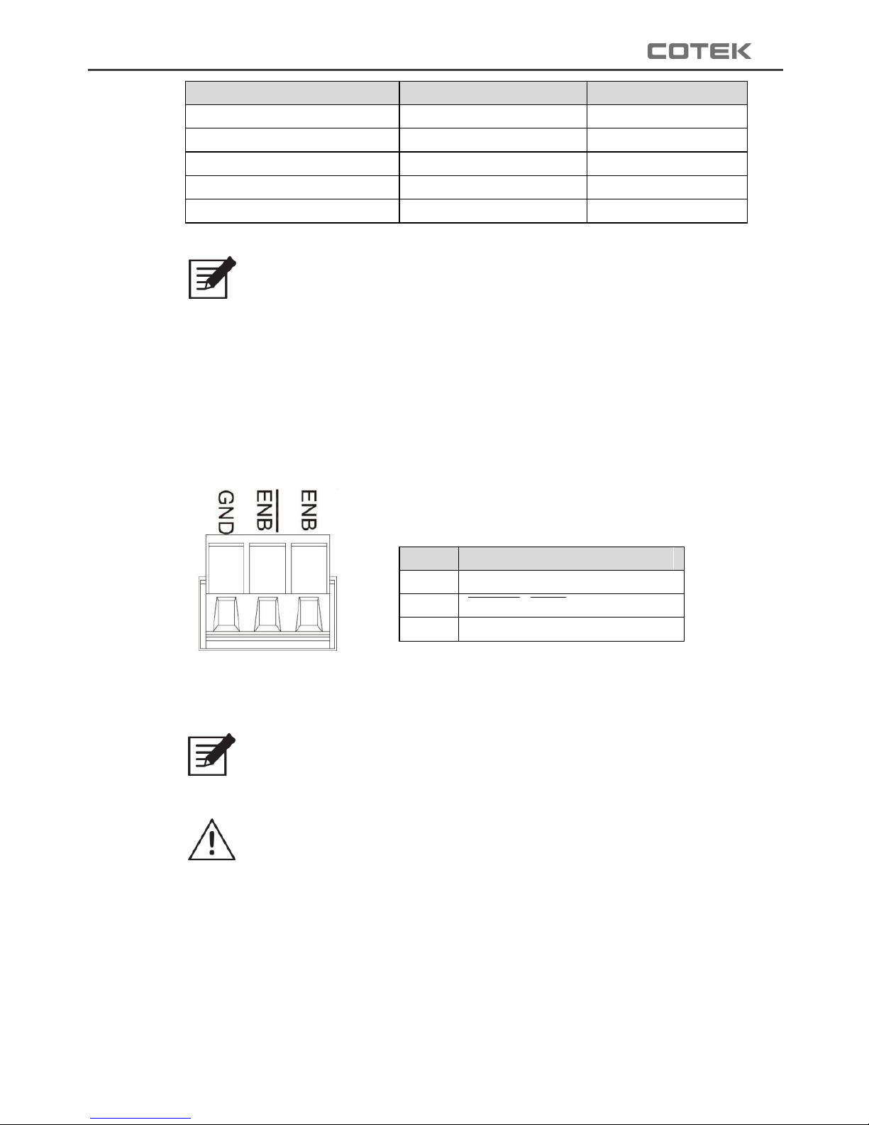
3-2-2. Green Terminal
Item
Description
1
GND
2
Enable (ENB)
3
Enable (ENB)
Table 17. SE series green terminal description
Figure 9. SE series green terminal
Note:
Fault conditions include Input under / over voltage, output short
circuit / over load, over / under temperature.
Caution!
Please follow the following steps for the installation.
Before installing the inverter, make sure the main switch is at “OFF”
position.
Before using the remote function, make sure the main switch pressed
toward “REMOTE”.
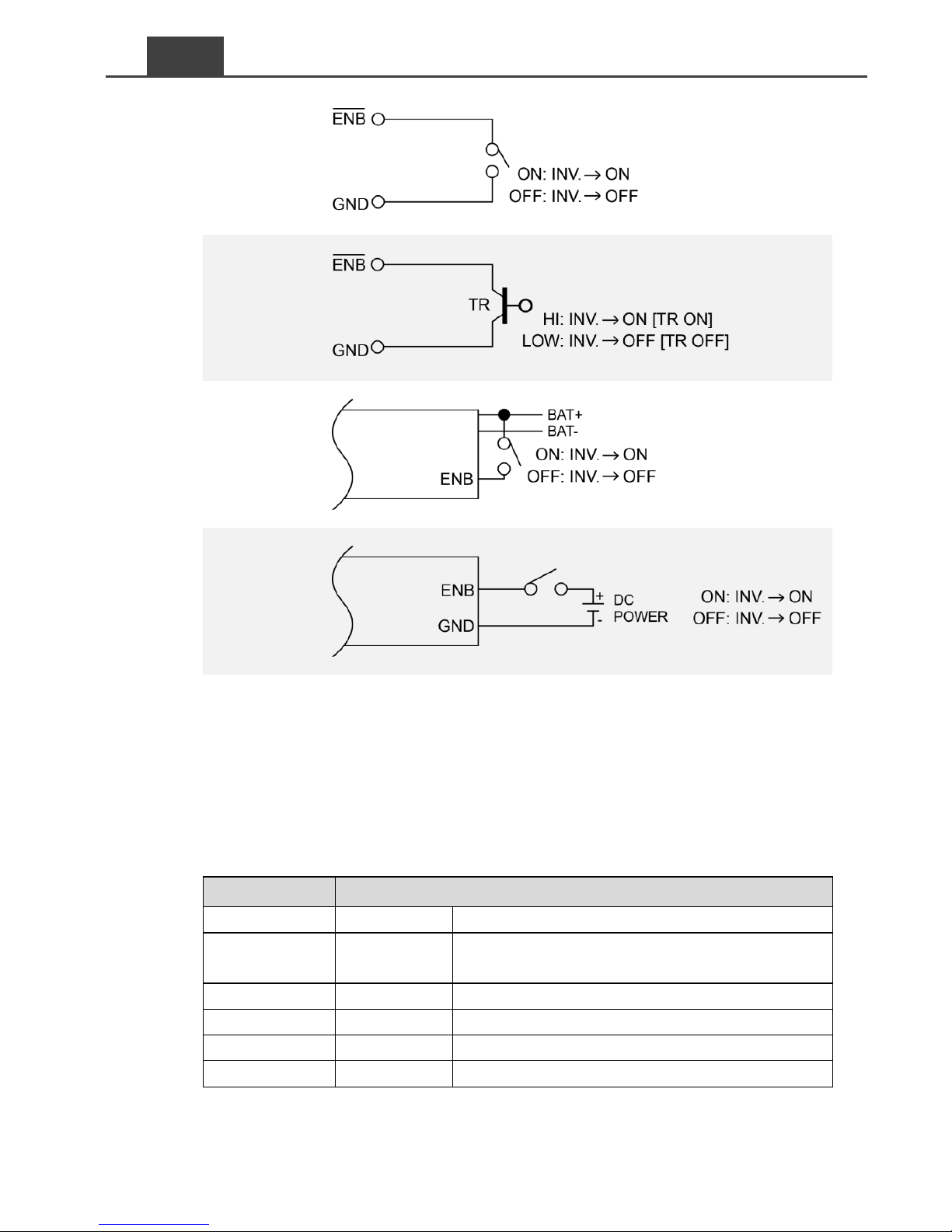
Use 20 ~ 24 #AWG wire to connect the remote control terminals.
Page 22
18
EN
Mode 1
Mode 2
Mode 3
Mode 4
Table 18. SE series wiring for control
3-2-3. Remote Port (RJ-11)
The SE400 inverter can be compatible with CR-8 remote control.
Before using the remote control, make sure the main switch on
inverter must be at “ REMOTE” position.
Pin Number
Signal Description
1
Reserved
─
2
GND
The same polarity as the battery negative
side 3 ─
─
4
─ ─ 5
RMT
Remote controller panel (positive)
6
─
─
Table 19. SE series green terminal signal description
Page 23
19
3-2-4. Chassis ground
Must be connected to earth ground prior to making any other
connections to the equipment.
3-3. Maintenance
Make sure that the fan vents are not blocked.
Use a vacuum cleaner to remove any dust from the fan area
When cleaning the case or front panel, use a soft, dry cloth, only. If
the case or front panel is very dirty, use a neutral, non-abrasive
detergent. Do not use alcohol or ammonia based solutions.
Regular service, and relocation of the inverter, should be performed
by a qualified service technician. Avoid spilling liquid on the inverter.
3-4. Inverter Installation and Operation
Before installing the inverter, make sure the main switch must be
“OFF”.
STEP 1.
Connect the DC cable, then connect
the DC cable to battery.
(Make sure the polarity)
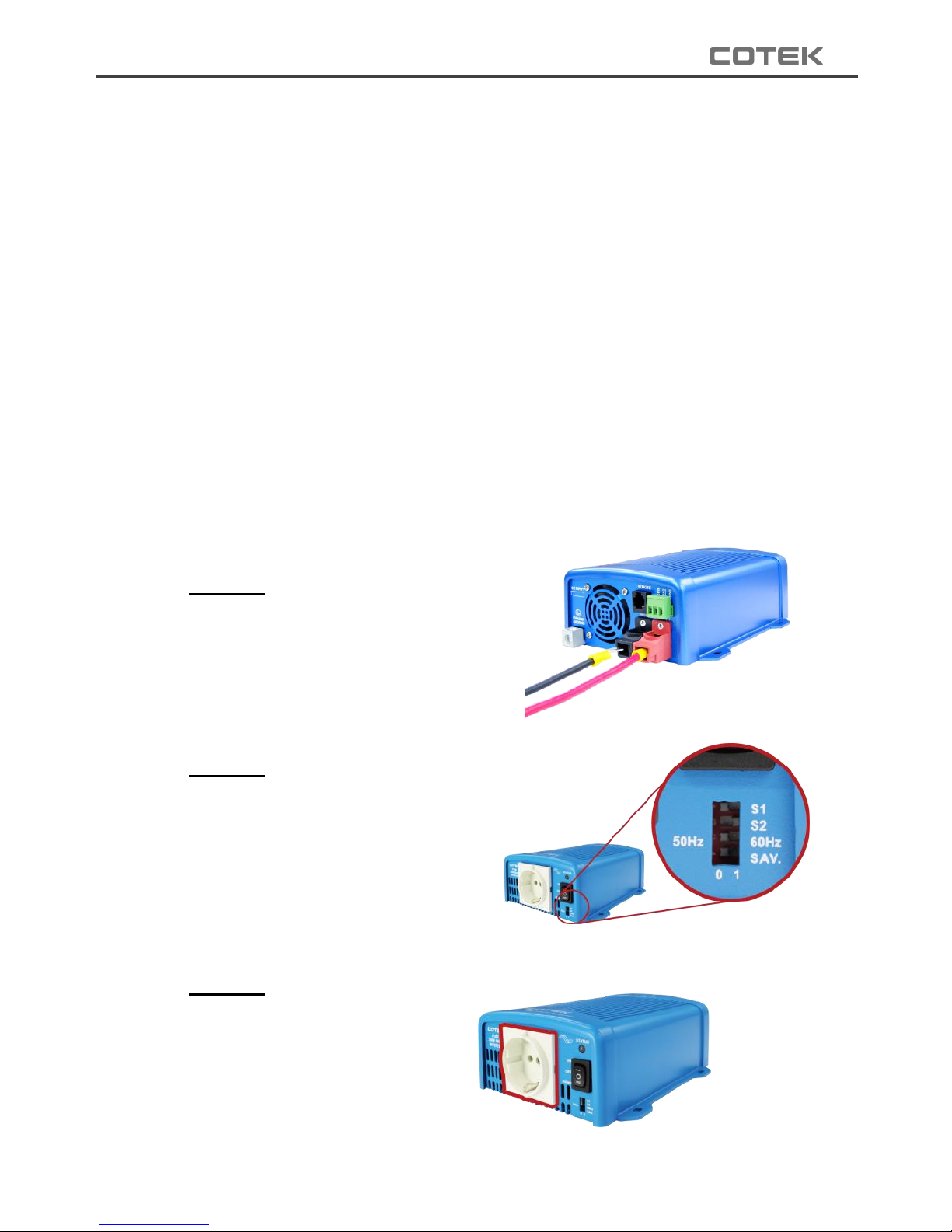
STEP 2.
Dip switch setting for AC output
voltage, frequency, and saving
mode. (Refer to 3-1-4.)
STEP 3.
Connect the AC cable.
Figure 10. Installation step 1
Figure 11. Installation step 2
Figure 12. Installation step 3
Page 24
20
EN
STEP 4.
Power ON.
The buzzer will send
out “Beep” sounds at
the moment the inverter
will do self-diagnosis,
then the power status
LED indicators will also
appear in various colors. Finally the buzzer will sound another “Beep”
and the power status LED indicators will turn to solid “Green” color
(normal state), means the inverter is now ready to work.
Note:
1. If there is several loads used, turn them on separately after the
inverter has been “ON” in order to prevent the OVP present
caused by the surge power.
2. Set power inverter switch to the ON position and turn the test
load on. The inverter should supply power to the load. If you plan
to accurately measure the true output r.m.s. voltage of inverter, a
meter such as FLUKE 45 BECKMAN 4410 or TRIPLETT 4200
must be used.
Figure 13. Installation step 4
Page 25
21
4. Operation
4-1. Connecting the DC Cable
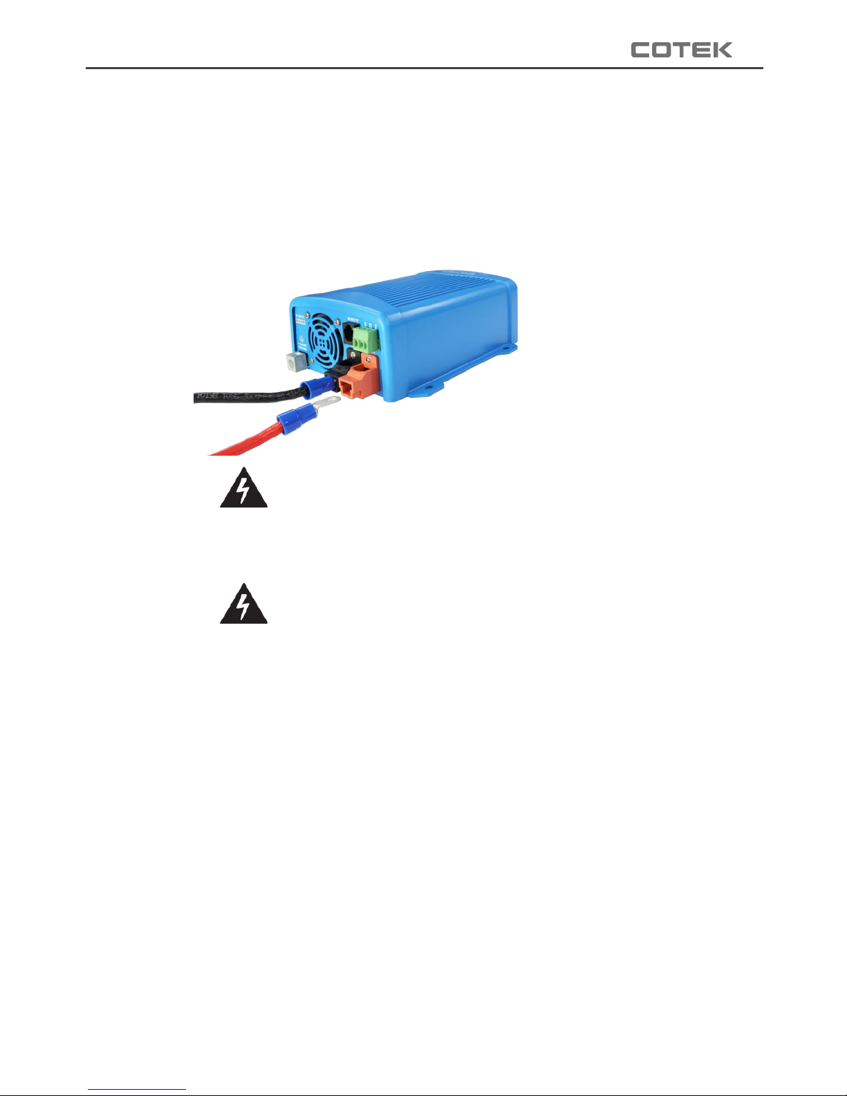
Connect DC input terminals to 12V / 24V /48V battery or other DC
power source [ + ] is positive, [ - ] is negative. Reverse polarity
connection can blow the internal fuse and may damage the
inverter permanently.
Figure 14. DC cable connection
Warning! Make sure that all the DC connections are
tight (torque to 9 – 10 ft-lbs, 11.7 – 13 Nm). Loose
connections could result in overheating and can be a
potential hazard.
Warning! The recommended inline fuse should be
installed as close to the battery positive terminal as
possible failure to use a fuse on the “+” cable running
between the inverter and battery may cause damage
to the cable / inverter and will void warranty.
Also, only use high quality copper wire and keep the cable length
short which is a maximum of 3 - 6 feet.
4-2. Connecting the Input Power
Before making the DC input side connections, the main switch
must be at “OFF”.
4-3. Connecting the Loads
Calculate the total power consumption of the output load. Make
sure that the total power consumption does not exceed the rated
power.
Page 26
22
EN
If the total power consumption over the rated power of the inverter,
remove the non-critical: loads until the total power consumption is
below the rated power.
4-4. Switch ON Inverter
Set the power switch to the “ON” position. The inverter will carry
out self-diagnosis and, the LED’s will also appear various colors.
Set the power switch to the “OFF” position. The inverter stops and
all the lights that are on will go off.
4-5. Protection Mechanism
4-5-1. SE200 Protection Mechanism
Model
Over Voltage (DC)
Under Voltage
Alarm
Under Voltage
Shutdown
Restart
Shutdown
Restart
12V
16V ± 3%
14.5V± 3%
10.5V ± 3%
10.0V ± 3%
12.5V ± 3%
24V
32V ± 3%
29V ± 3%
21V± 3%
20V ± 3%
25V ± 3%
Table 20. SE200 DC input protection mechanism
Model
Over Temperature Protection
Shutdown
Restart
12V
90 ± 3℃
50 ± 3℃
24V
Table 21. SE200 over temperature protection mechanism
4-5-2. SE350 protection mechanism
Model
Over Voltage (DC)
Under Voltage
Alarm
Under Voltage
Shutdown
Restart
Shutdown
Restart
12V
15.5V ± 0.25V
14.5V± 0.25V
10.5V ± 0.25V
10V ± 0.25V
12V± 0.25V
24V
31V ± 0.5V
29V ± 0.5V
21V± 0.5V
20V ± 0.5V
24V ± 0.5V
48V
62 ± 1V
58V ± 1V
42V± 1V
40V ± 1V
48 ± 1V
Table 22. SE350 DC input protection mechanism
Model
Over Temperature Protection
Shutdown
Restart
12V
83 ± 5℃
53 ± 5℃
24V
48V
Table 23. SE350 over temperature protection mechanism
Page 27
23
4-5-3. SE400 Protection Mechanism
Model
Over Voltage (DC)
Under Voltage
Alarm
Under Voltage
Shutdown
Restart
Shutdown
Restart
12V
16V ± 0.3V
14.5V± 0.3V
10.5V ± 0.3V
10.5V ±
0.3V
12.5V± 0.3V
24V
32V ± 0.5V
29V ± 0.5V
21V± 0.5V
21V ± 0.5V
25V ± 0.5V
48V
64 ± 1V
58V ± 1V
42V± 1V
42V ± 1V
50 ± 1V
Table 24. SE400 DC input protection mechanism
Model
Over Temperature Protection
Shutdown
Restart
12V
80℃
60℃
24V
48V
Table 25. SE400 over temperature protection mechanism
4-6. Troubleshooting Guide
Warning! Do not open or disassemble the inverter.
Attempting to service the unit yourself may result in a risk of
electrical shock or fire.
SE200 / SE350 troubleshooting guide
LED Signal
Descriptio
n
Solutions
LED flashes orange
light slowly with 5 short
beeps every 15
seconds
Under
voltage
alarm
1. Chec
k connections and cable.
2. Rech
arge battery.
LED flashes orange
light every 0.1 seconds
Over voltage
Check input voltage. Reduce input
voltage to meet SE200 / SE350.
LED lights red; following
two short beeps.
Inverter shuts down
after 3 minutes and
restart 3 times
O/P over
load
Reduce load.
In case of restart failed, please turn on
the unit manually.
LED lights red; following
two short beeps.
O/P short
circuit
Check AC wiring, make sure no circuit.
In case of restart failed, please turn on
the unit manually.
Page 28
24
EN
LED Signal
Descriptio
n
Solutions
Inverter shuts down
after two seconds and
restart 3 times
LED flashes red light
quickly twice every 1.6
seconds
Over
temperature
Improve ventilation. Make sure
ventilation openings in inverter are not
obstructed. Reduce ambient
temperature.
LED flashes red light
every 0.4 seconds, then
inverter shuts down
Shut down
under
voltage
Recharge battery. Check connections
and cable. Please turn on the unit
manually.
LED flashes red light
every 0.1 seconds, then
inverter shut down
Shut down
over voltage
Check input voltage. Reduce input
voltage. Please turn on the unit
manually.
LED flashes red light
slowly once and quickly
twice every 1.6 seconds
Fan alarm
1. Check fan connection wire
2. Clean the dust on the fan
Table 26. SE200 / SE350 troubleshooting guide
SE400 troubleshooting guide
LED Signal
Description
Solutions
LED fast blink orange light
with two long beeps
Over load
400W ~ 460W
(100% ~ 115%)
Reduce load.
In case of restart failed,
please turn on the unit
manually.
LED slow blink orange light
Over temperature
Under temperature
Improve ventilation. Make
sure ventilation openings in
inverter are not obstructed.
Reduce ambient
temperature.
LED lights in solid red with
one short beeps
Over current
Over load
> 460W (115%)
Reduce load.
In case of restart failed,
please turn on the unit
manually.
LED fast blink red light
Over voltage
Check input voltage. Reduce
input voltage to meet SE400
LED slow blink red light with
one long beeps &two short
Under voltage
Recharge battery. Check
connections and cable.
Please turn on the unit
Page 29
25
LED Signal
Description
Solutions
beeps
manually.
Table 27. SE400 troubleshooting guide
4. Warranty
5-1 Warning
Warning!
Do not open or disassemble the Inverter. Attempting to do
so may cause risk of electrical shock or fire.
5-2 Warranty
We guarantee this product against defects in materials and
workmanship for a period of 24 months from the date of purchase.
In case you need to repair or replace any defective power
inverters, please contact COTEK local distributor.
This warranty will be considered void if the unit has been misused,
altered, or accidentally damaged. COTEK is not liable for anything
that occurs as a result of the user’s fault.
Page 30

26
FR
Table des matières
1. CONSIGNES DE SECURITE ............................................................................. 29
1-1. ... Consignes générales 29
1-2. ... Précautions 30
2. CARACTERISTIQUES ...................................................................................... 31
2-1. Caractéristiques 31
2-2. Schéma de principe 31
2-3. Caractéristiques électriques 32
2-3-1 Caractéristiques du SE200 ....................................................................... 32
2-3-2. Caractéristiques du SE350 ...................................................................... 33
2-3-3. Caractéristiques du SE400 ...................................................................... 35
2-4. Schémas d’encombrement 39
3. INSTALLATION ET MAINTENANCE ................................................................ 40
3-1. Panneau avant 40
3-2. Panneau arrière 43
3-3. Entretien 46
3-4. Installation et mise en service 47
4. UTILISATION ..................................................................................................... 48
4.1. Connexion aux bornes d’alimentation CC 48
4.2. Connexion à la source CC 49
4.3. Connexion des consommateurs 49
4.4. Mise sous tension 49
4.5. Protections 49
Page 31

27
4-5-1. SE200 ...................................................................................................... 49
4-5-2. SE350 ...................................................................................................... 50
4-5-3. SE400 ...................................................................................................... 50
4.6. Guide de dépannage 51
5. GARANTIE ........................................................................................................ 53
5-1 Attention 53
5-2 Garantie 53
Page 32

28
FR
Dispositions légales
Copyrights 2017 COTEK Electronic IND. CO. tous droits réservés.
Aucune partie de ce document ne peut être reproduite, quelle qu’en soit la manière et quel
qu’en soit le but, sans autorisation préalable écrite de COTEK Electronic IND. CO. Pour obtenir
l’autorisation de publier ce manuel, adressez-vous directement à COTEK Electronic IND. CO.,
LTD. Pour l’ensemble des activités COTEK, ni COTEK Electronic IND. CO., LTD. ni ses
distributeurs ou revendeurs ne sauraient être tenus responsables, d’aucune manière, de tout
dommage direct, indirect ou accessoire. Les caractéristiques peuvent être modifiées sans
notification préalable.
Tout a été mis en oeuvre pour que ce document soit complet, précis et à jour. COTEK
Electronic IND. CO., LTD. se réserve le droit d’apporter des modifications sans notification et
ne saurait être tenu responsable de tout dommage direct, indirect ou accessoire causé par
l’utilisation de ce contenu, y compris mais non limité à des omissions, des coquilles, des
erreurs de calcul ou de description. Toutes les marques sont protégées même sans indication
spécifique. L’absence de logo ne signifie pas que le produit ou la marque ne sont pas protégés.
Page 33

29
1. Consignes de sécurité
1-1. Consignes générales
AVERTISSEMENT !
Avant d'installer ou d'utiliser l'onduleur, il est nécessaire de lire et
bien comprendre les instructions concernant la sécurité.
Ne pas exposer l'onduleur à la pluie, à la neige ou aux projections d'eau.
Ne pas le stocker dans la cale ni l'exposer à la poussière. Pour éviter les
risques électriques ne pas couvrir ni obstruer les grilles de ventilation. Ne
pas installer l'onduleur dans un compartiment non aéré au risque de
provoquer une surchauffe.
Pour éviter les risques d'incendie et de chocs électriques, s'assurer que
les câbles de connexion sont en bon état et d'une section suffisante. Ne
pas utiliser l'onduleur avec un câblage en mauvais état ou de mauvaise
qualité.
Certains composants de l'onduleur peuvent provoquer des arcs
électriques ou des étincelles. Pour éviter les risques d'incendie ou
d'explosion, l'onduleur ne doit pas être installé à proximité des batteries
ou de matériaux inflammables ni dans un local nécessitant une protection
anti-déflagration. Cette précaution s'étend aux locaux des machines à
essence, des réservoirs à carburant ou de leurs conduites.
En fonction de l’application, l’utilisateur peut être amené à monter une
protection (fusible ou disjoncteur) sur la sortie CA de l’onduleur. Les
câbles et connecteurs ne sont pas fournis pour ce branchement.
Un disjoncteur de 20 A, modèles SE200 & SE350, ou de 10 A, modèle
SE400, sera nécessaire sur la sortie CA.
Prendre les précautions suivantes en cas d’intervention sur l’onduleur :
Ne porter aucun bijou (montre, bague) ou autre accessoire métallique.
Utiliser des outils isolés.
Utiliser des gants de protection et des chaussures en caoutchouc.
Page 34

30
FR
1-2. Précautions
À réception, vérifier l’état de l’emballage. S’il est endommagé, en informer
votre distributeur.
Ne pas utiliser l’onduleur à proximité d’une source en eau ou dans un
environnement excessivement humide.
Bien serrer les branchements CC.
La liaison à la masse doit être fiable et permanente.
Ne pas laisser tomber d’objets métalliques sur la batterie. L’étincelle ou le
court-circuit en résultant pourrait provoquer une explosion.
Installer l’onduleur dans un lieu correctement ventilé. Ne pas obstruer les
grilles de ventilation sur l’avant (prise d’air frais) et sur l’arrière (sortie air
chaud).
L’onduleur doit disposer d’une alimentation adéquate. S’assurer que la
section des câbles soit suffisante.
Placer l’onduleur de manière à ce que l’axe du ventilateur soit horizontal.
Ne pas utiliser l’onduleur à proximité d’une source de carburant ou d’un
feu ouvert.
Ne pas raccorder de consommateurs susceptibles de créer des retours
de courant à l’onduleur.
Pour des performances optimales, veiller à respecter la plage de
températures admissibles : -20°C à +60°C (températures ambiantes). Le
flux de l’air ne doit jamais être entravé.
Page 35
31
2. Caractéristiques
2-1. Caractéristiques
Les onduleurs de la série SE sont des appareils CC-CA de grande fiabilité,
à base de composants électroniques et micro-processeurs dernière
génération. Ils offrent les caractéristiques suivantes:
Signal de sortie sinusoïdal pur :
SE200:DHT < 3% - SE350 : DHT < 3% - SE400 : DHT < 5%
Gestion d’énergie par algorithmes.
Ventilateur de refroidissement asservi à la charge et à la température.
Compatible avec les commandes type CR-8.
Bornes à contact sec.
Protection étendue :
Entrée :
tension haute / tension basse.
inversion de polarité ( fusible).
Sortie :
surchauffe.
surcharge.
court-circuit.
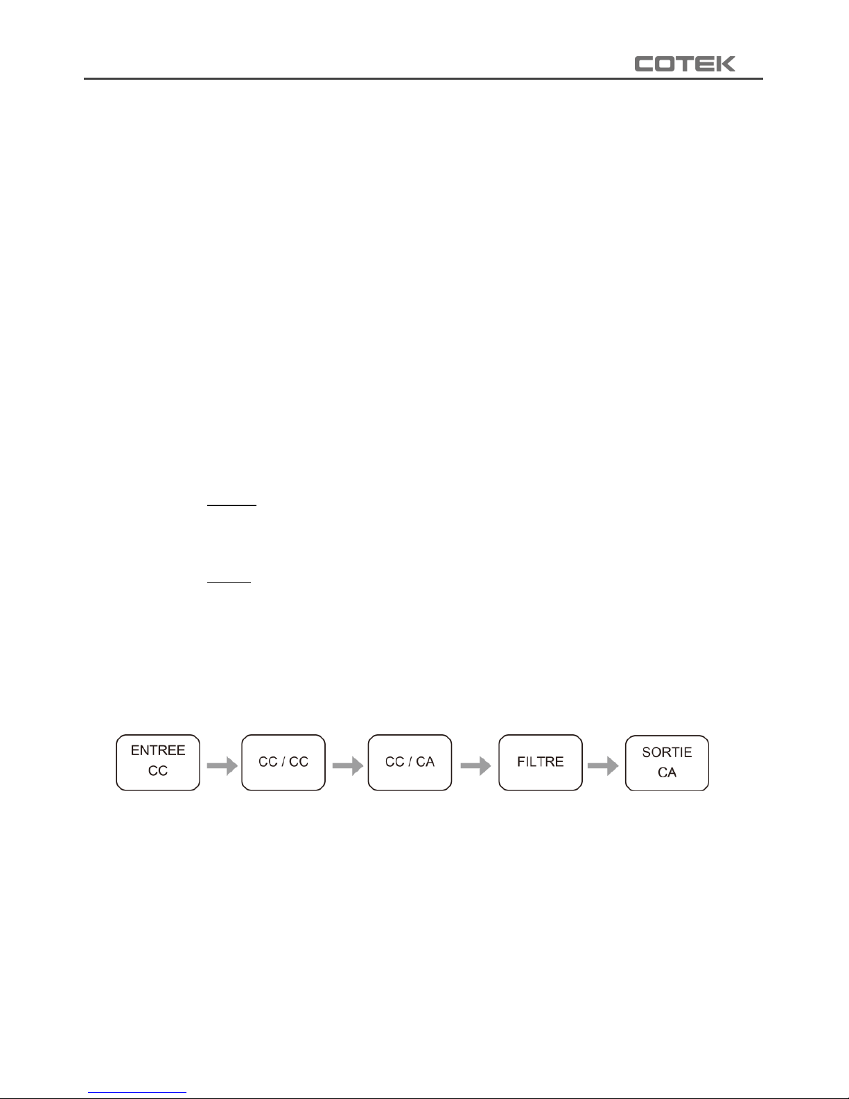
2-2. Schéma de principe
Page 36
32
FR
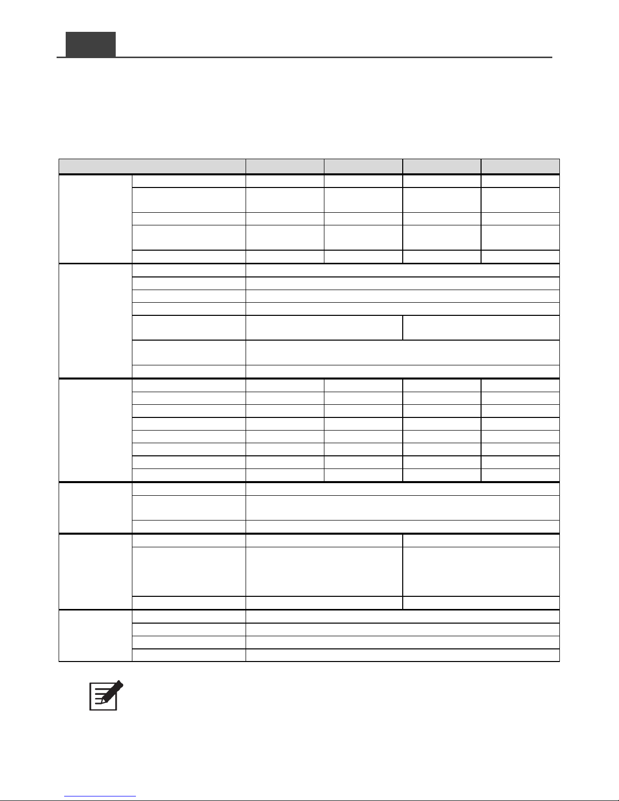
2-3. Caractéristiques électriques
2-3-1 Caractéristiques du SE200
Modèle
SE200-112
SE200-124
SE200-212
SE200-224
Entrée
Tension d’entrée
12VCC
24VCC
12VCC
24VCC
Plage de tensions
admissibles
10.0~16.0VCC
20.0~32.0VCC
10.0~16.0VCC
20.0~32.0VCC
Consommation à vide
< 0.5A
< 0.4A
< 0.5A
< 0.4A
Consommation en mode
économie énergie
< 0.12A
< 0.06A
< 0.12A
< 0.06A
Rendement
89%
91%
91%
93%
Sortie
Puissance nominale
200 W
Puissance crête (3 min.)
230 W
Puissance crête (3 s.)
250 W
Fréquence
50 / 60 Hz ± 0.5% (modifiable par interrupteurs DIP)
Tension de sortie
100 / 110 / 115 / 120 VCA ± 5%
(modifiable par interrupteurs DIP)
200 / 220 / 230 / 240 VCA ± 5%
(modifiable par interrupteurs DIP)
Redémarrage
court-circuit
3 tentatives entrecoupées de 2 secondes d’arrêt
Forme du signal
Pur sinus (DHT < 3% @ charge standard)
Protections
Tension haute batterie
16.0VCC ± 3%
32.0VCC ± 3%
16.0VCC ± 3%
32.0VCC ± 3%
Tension basse batterie
10.0VCC ± 3%
20.0VCC ± 3%
10.0VCC ± 3%
20.0VCC ± 3%
Coupure tension basse
10.0VCC ± 3%
20.0VCC ± 3%
10.0VCC ± 3%
20.0VCC ± 3%
Alarme tension basse
10.5VCC ± 3%
21.0VCC ± 3%
10.5VCC ± 3%
21.0VCC ± 3%
Reprise tension basse
12.5VCC ± 3%
25.0VCC ± 3%
12.5VCC ± 3%
25.0VCC ± 3%
Alarme tension haute
15.5VCC ± 3%
31.0VCC ± 3%
15.5VCC ± 3%
31.0VCC ± 3%
Coupure tension haute
16.0VCC ± 3%
32.0VCC ± 3%
16.0VCC ± 3%
32.0VCC ± 3%
Reprise tension haute
14.5VCC ± 3%
29.0VCC ± 3%
14.5VCC ± 3%
29.0VCC ± 3%
Environnement
Température de travail
-20°C ~ +60°C
Température de
stockage
-30°C ~ +70°C
Humidité, travail
10 ~ 95%, humidité relative sans condensation
Normes
Sécurité
----
EN 60950-1
CEM
FCC classe B
EN55022; EN61204-3
EN61000-6-1, 6-3
EN61000-3-2, -3-3; EN55024
EN61000-4-2, 3, 4, 5, 6, 8, 11
E-mark
----
CISPR 25; ISO 7637-2
Autres
Dimensions (lxHxP)
150 mm x 68 mm x187 mm
Poids
1.6 kg
Commande déportée
CR-8 (option)
Refroidissement
Ventilateur asservi à la charge et à la température
Tableau 1. SE200 - Caracté ristiques
Note:
Tests réalisés avec une tension d’entrée dans les limites admissibles et une
température ambiante égale à 25°C.
Page 37
33
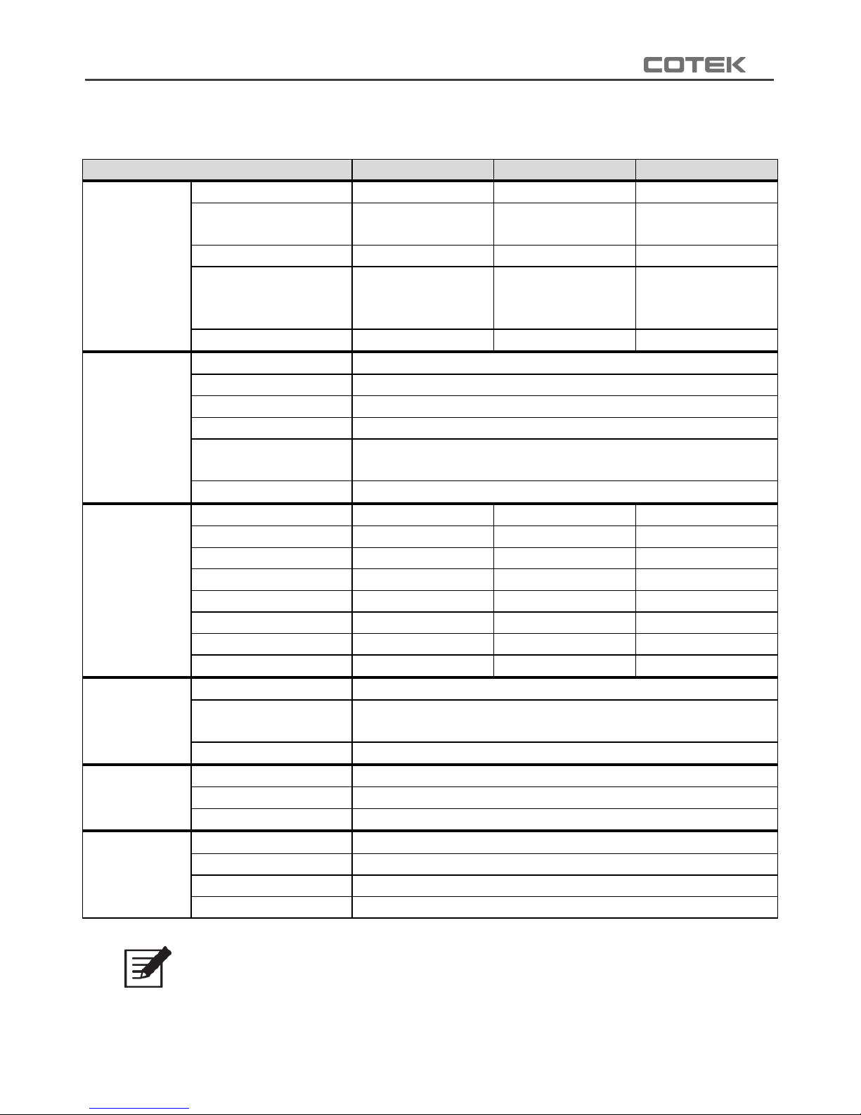
2-3-2. Caractéristiques du SE350
Modèle
SE350-112
SE350-124
SE350-148
Entrée
Tension d’entrée
12VCC
24VCC
48VCC
Plage de tensions
admissibles
10.0~15.5VCC
20.0~31.0VCC
40.0~62.0VCC
Consommation à vide
< 0.65A
< 0.32A
< 0.16A
Consommation en
mode économie
d’énergie
< 90mA
< 60mA
< 40mA
Rendement
87%
88%
89%
Sortie
Puissance nominale
350 W
Puissance crête
700 W
Fréquence
50 / 60 Hz ± 0.1% (modifiable par interrupteurs DIP)
Tension de sortie
100 / 110 / 115 / 120 VCA ± 5% (modifiable par interrupteurs DIP)
Redémarrage
court-circuit
4 tentatives entrecoupées de 2 secondes d’arrêt
Forme du signal
Pur sinus (DHT < 3% @ charge standard)
Protections
Tension haute batterie
15.5V ± 0.25V
31.0V ± 0.5V
62.0V ± 1V
Tension basse batterie
10.0V ± 0.25V
20.0V ± 0.5V
40.0V ± 1V
Coupure tension basse
10.0V ± 0.25V
20.0V ± 0.5V
40.0V ± 1V
Alarme tension basse
10.5V ± 0.25V
21.0V ± 0.5V
42.0V ± 1V
Reprise tension basse
12.0V ± 0.25V
24.0V ± 0.5V
48.0V ± 1V
Alarme tension haute
15.0V ± 0.25V
30.0V ± 0.5V
60.0V ± 1V
Coupure tension haute
15.5V ± 0.25V
31.0V ± 0.5V
62.0V ± 1V
Reprise tension haute
14.5V ± 0.25V
29.0V ± 0.5V
58.0V ± 1V
Environnement
Température de travail
-20°C ~ +60°C
Température de
stockage
-30°C ~ +70°C
Humidité, travail
90%, humidité relative sans condensation
Normes
Sécurité
----
CEM
----
E-mark
----
Autres
Dimensions (lxHxP)
150 mm X 68 mm X187 mm
Poids
1.6 kg
Commande déportée
CR-8 (option)
Refroidissement
Ventilateur asservi à la charge et à la température
Tableau 2. SE350 – Caractéristiques modè les 100/110/115/120 VCA
Note:
Pour ce qui concerne les performances en fonction de la température, voir schéma 1.
Page 38
34
FR
Modèle
SE350-212
SE350-224
SE350-248
Entrée
Tension d’entrée
12VCC
24VCC
48VCC
Plage de tension
admissibles
10.0~15.5VCC
20.0~31.0VCC
40.0~62.0VCC
Consommation à vide
< 0.9A
< 0.5A
< 0.25A
Consommation en mode
économie d’énergie
< 90mA
< 60mA
< 40mA
Rendement
89%
90%
91%
Sortie
Puissance nominale
350 W
Puissance crête
700 W
Fréquence
50 / 60 Hz ± 0.1% (modifiable par interrupteurs DIP)
Tension de sortie
200 / 220 / 230 / 240 VCA ± 5% (modifiable par interrupteurs DIP)
Redémarrage
court-circuit
4 tentatives entrecoupées de 2 secondes d’arrêt
Forme du signal
Pur sinus (DHT < 3% @ charge standard)
Protections
Tension haute batterie
15.5V ± 0.25V
31.0V ± 0.5V
62.0V ± 1V
Tension basse batterie
10.0V ± 0.25V
20.0V ± 0.5V
40.0V ± 1V
Coupure tension basse
10.0V ± 0.25V
20.0V ± 0.5V
40.0V ± 1V
Alarme tension basse
10.5V ± 0.25V
21.0V ± 0.5V
42.0V ± 1V
Reprise tension basse
12.0V ± 0.25V
24.0V ± 0.5V
48.0V ± 1V
Alarme tension haute
15.0V ± 0.25V
30.0V ± 0.5V
60.0V ± 1V
Coupure tension haute
15.5V ± 0.25V
31.0V ± 0.5V
62.0V ± 1V
Reprise tension haute
14.5V ± 0.25V
29.0V ± 0.5V
58.0V ± 1V
Environnement
Température de travail
-20°C ~ +60°C
Température de
stockage
-30°C ~ +70°C
Humidité, travail
90%, humidité relative sans condensation
Normes
Sécurité
EN 60950-1
CEM
EN55022 class B, EN 55024; EN61204-3
EN61000-3-2, -3-3; EN 61000-6-1, -6-3
IEC 61000-4-2, 3, 4, 5, 6, 8, 11
E-mark
CISPR 25; ISO 7637-2
Autres
Dimensions (lxHxP)
150 mm X 68 mm X187 mm
Poids
1.6 kg
Commande déportée
CR-8 (option)
Refroidissement
Ventilateur asservi à la charge et à la température
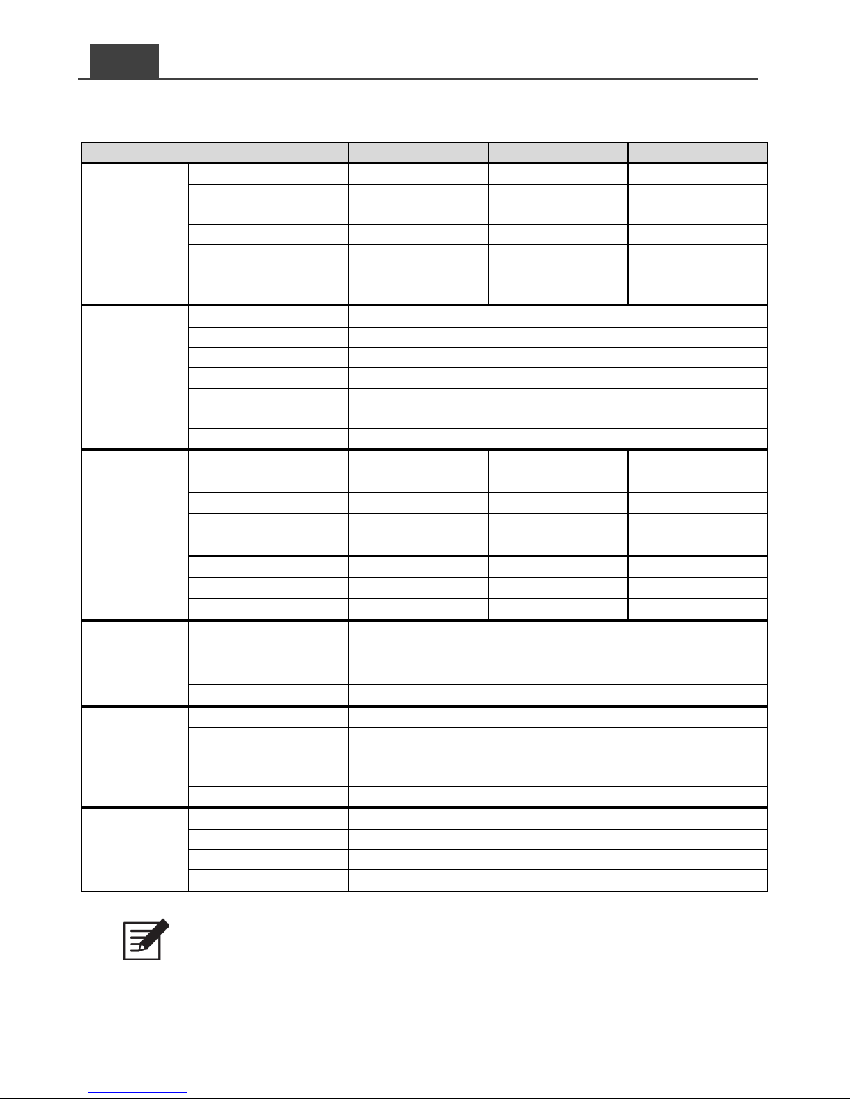
Tableau 3. SE350 – Caractéristiques modè les 200/220/230/240 VCA
Note:
Pour ce qui concerne les performances en fonction de la température, voir schéma 1.
Page 39
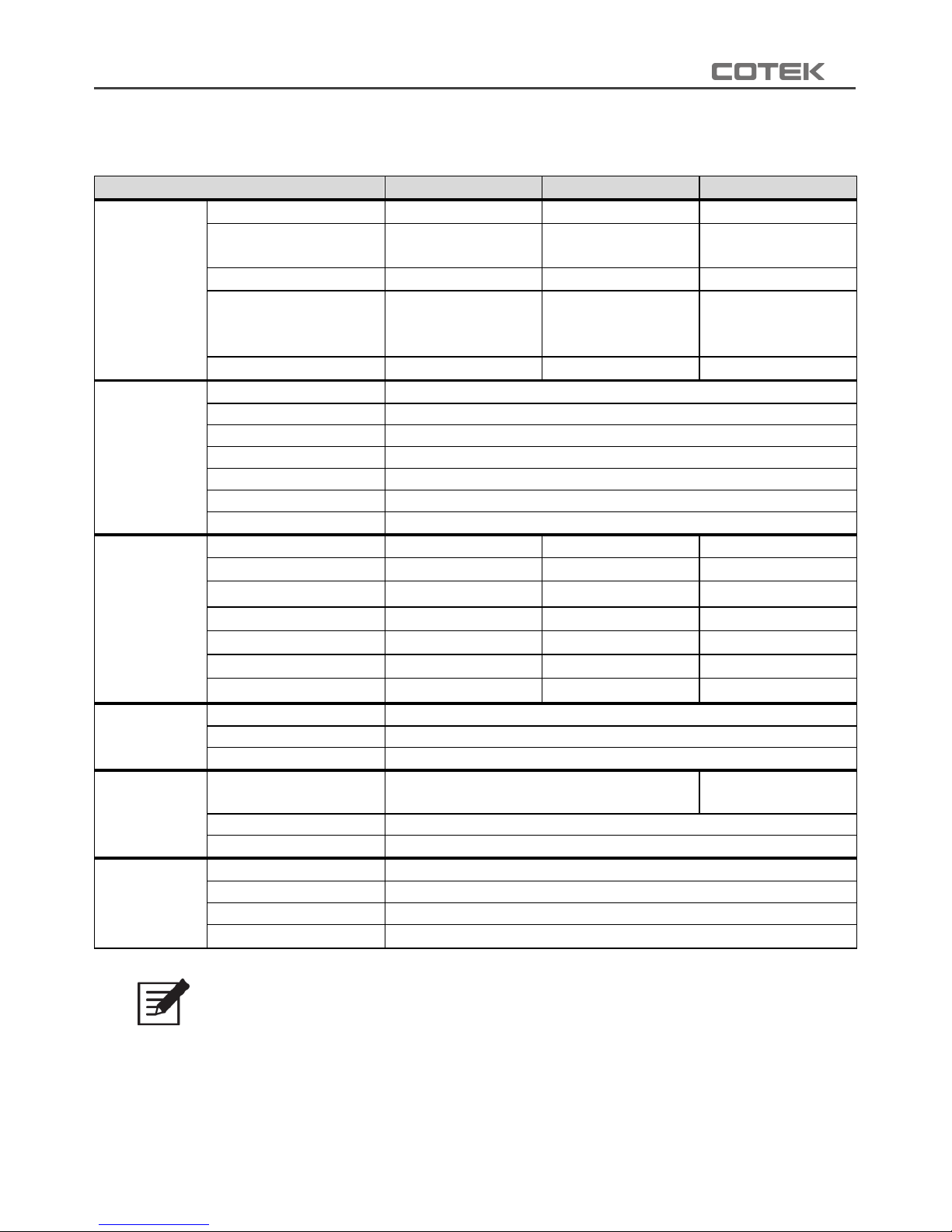
35
2-3-3. Caractéristiques du SE400
Modèle
SE400-112
SE400-124
SE400-148
Entrée
Tension d’entrée
12VCC
24VCC
48VCC
Plage de tension
admissibles
10.5~16.0VCC
21.0~32.0VCC
42.0~64.0VCC
Consommation à vide
<1A @12VCC
<0.5A @24VCC
<0.25A @48VCC
Consommation en
mode économie
d’énergie
<0.2A @12VCC
<0.1A @24VCC
<0.05A @48VCC
Rendement
88%
89%
90%
Sortie
Puissance nominale
400 W (± 3%)
Puissance crête (1 min.)
> 400 W~460 W (100%~115%)
Puissance crête (1 s.)
< 800 W
Fréquence
50 / 60 Hz ± 0.5% (modifiable par interrupteurs DIP)
Tension de sortie
100 / 110 / 115 / 120 VCA ± 5% (modifiable par interrupteurs DIP)
Protection court-circuit
1 seconde d’arrêt
Forme du signal
Pur sinus (DHT < 5% @ charge standard)
Protections
Tension haute batterie
16.0 ± 0.3VCC
32.0 ± 0.5VCC
64.0 ± 1.0VCC
Tension basse batterie
10.5 ± 0.3VCC
21.0 ± 0.5VCC
42.0 ± 1.0VCC
Coupure tension basse
10.5 ± 0.3VCC
21.0 ± 0.5VCC
42.0 ± 1.0VCC
Alarme tension basse
10.5 ± 0.3VCC
21.0 ± 0.5VCC
42.0 ± 1.0VCC
Reprise tension basse
14.5V± 0.3V
28.0 ± 0.5VCC
56.0 ± 0.5VCC
Alarme tension haute
16.0 ± 0.3VCC
32.0 ± 0.3VCC
64.0 ± 0.3VCC
Coupure tension haute
12.5V± 0.3VCC
25.0V± 0.3VCC
50.0± 0.3VCC
Environnement
Température de travail
-20°C ~ +60°C
Température de stockage
-30°C ~ +70°C
Humidité, travail
10~95%, humidité relative sans condensation
Normes
Sécurité
UL 458
(UL, modèles avec GFCI uniquement)
----
EMC standards
FCC class B
E-mark
----
Autres
Dimensions (lxHxP)
150 mm x 68 mm x187 mm
Poids
1.256 kg
Commande déportée
CR-8 (option)
Refroidissement
Ventilateur asservi à la charge et à la température
Tableau 4. SE400 – Caractéristiques modè les 100/110/115/120 VCA
Note:
Conditions de charge nominale : Vin =12.5V/25V/50V, Vo=100/110/115/120VAC,
niveau de charge = 80% (facteur de puissance =1.0).
Efficacité en fonction de la tension:voir schéma 2.
Performances en fonction de la température:voir schéma 3.
Page 40
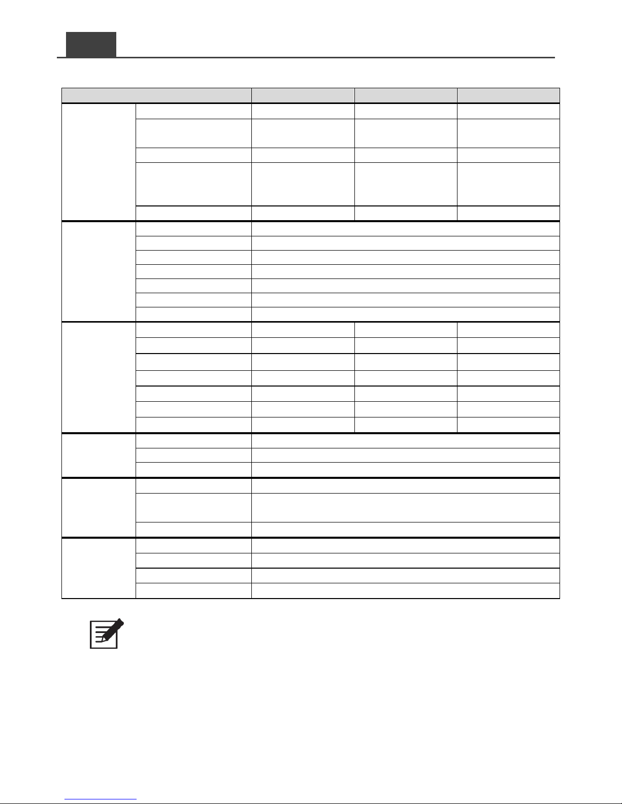
36
FR
Modèle
SE400-212
SE400-224
SE400-248
Entrée
Tension d’entrée
12VCC
24VCC
48VCC
Plage de tension
admissibles
10.5~16.0VCC
21.0~32.0VCC
42.0~64.0VCC
Consommation à vide
<1A @12VCC
<0.5A @24VCC
<0.25A @48VCC
Consommation en
mode économie
d’énergie
<0.2A @12VCC
<0.1A @24VCC
<0.05A @48VCC
Rendement
88%
89%
90%
Sortie
Puissance nominale
400 W (± 3%)
Puissance crête (1 min.)
> 400 W~460 W (100%~115%)
Puissance crête (1 s.)
< 800 W
Fréquence
50 / 60 Hz ± 0.5% (modifiable par interrupteurs DIP)
Tension de sortie
200 / 220 / 230 / 240 VCA ± 5% (Modifiable par interrupteurs DIP)
Protection court-circuit
1 seconde d’arrêt
Forme du signal
Pur sinus (DHT < 5% @ charge standard)
Protections
Tension haute batterie
16.0 ± 0.3VCC
32.0 ± 0.5VCC
64.0 ± 1.0VCC
Tension basse batterie
10.5 ± 0.3VCC
21.0 ± 0.5VCC
42.0 ± 1.0VCC
Coupure tension basse
10.5 ± 0.3VCC
21.0 ± 0.5VCC
42.0 ± 1.0VCC
Alarme tension basse
10.5 ± 0.3VCC
21.0 ± 0.5VCC
42.0 ± 1.0VCC
Reprise tension basse
14.5V± 0.3V
28.0 ± 0.5VCC
56.0 ± 0.5VCC
Alarme tension haute
16.0 ± 0.3VCC
32.0 ± 0.3VCC
64.0 ± 0.3VCC
Coupure tension haute
12.5V± 0.3VCC
25.0V± 0.3VCC
50.0± 0.3VCC
Environnement
Température de travail
-20°C ~ +60°C
Température de stockage
-30°C ~ +70°C
Humidité, travail
10~95%, humidité relative sans condensation
Normes
Sécurité
EN 62368-1
EMC standards
EN55032 class B; EN 55024; EN 61000-3-2, -3-3
IEC61000-4-2, 3, 4, 5, 6, 8, 11
E-mark
CISPR 25; ISO11452-2; ISO 7637-2
Autres
Dimensions (lxHxP)
150 mm X 68 mm X187 mm
Poids
1.256 kg
Commande déportée
CR-8 (option)
Refroidissement
Ventilateur asservi à la charge et à la température
Tableau 5. SE400 – Caractéristiques modè les 200/220/230/240 VCA
Note:
Conditions de charge nominales : Vin =12.5V/25V/50V, Vo=200/220/230/240VAC,
niveau de charge = 80% (facteur de puissance =1.0).
Efficacité en fonction de la tension:voir schéma 2.
Performances en fonction de la température:voir schéma 3
Page 41
37
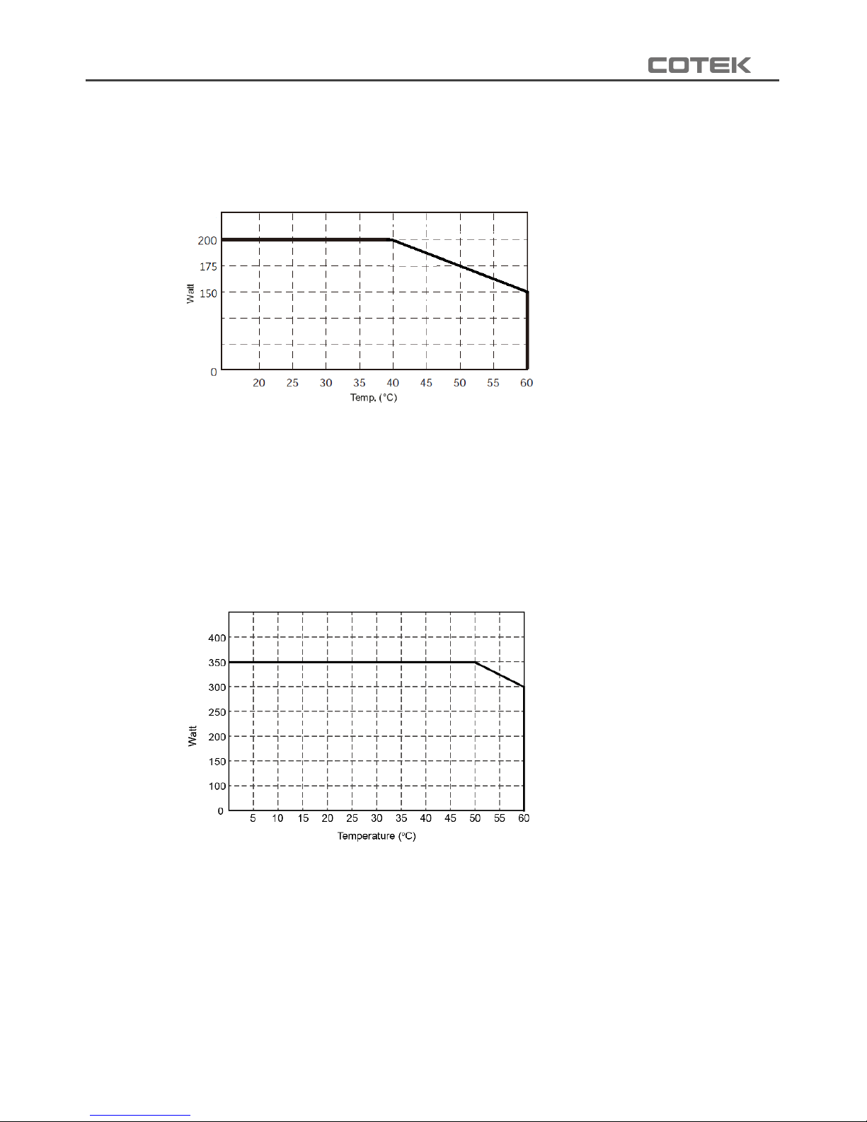
2-3-4. SE200 – Performances / Température
Schéma 1. SE200 Courbe de dé classement en fonction de la température
2-3-5. SE350 – Performances / Température
Sché ma 1. SE350 Courbe de déclassement en fonction de la température
Page 42
38
FR
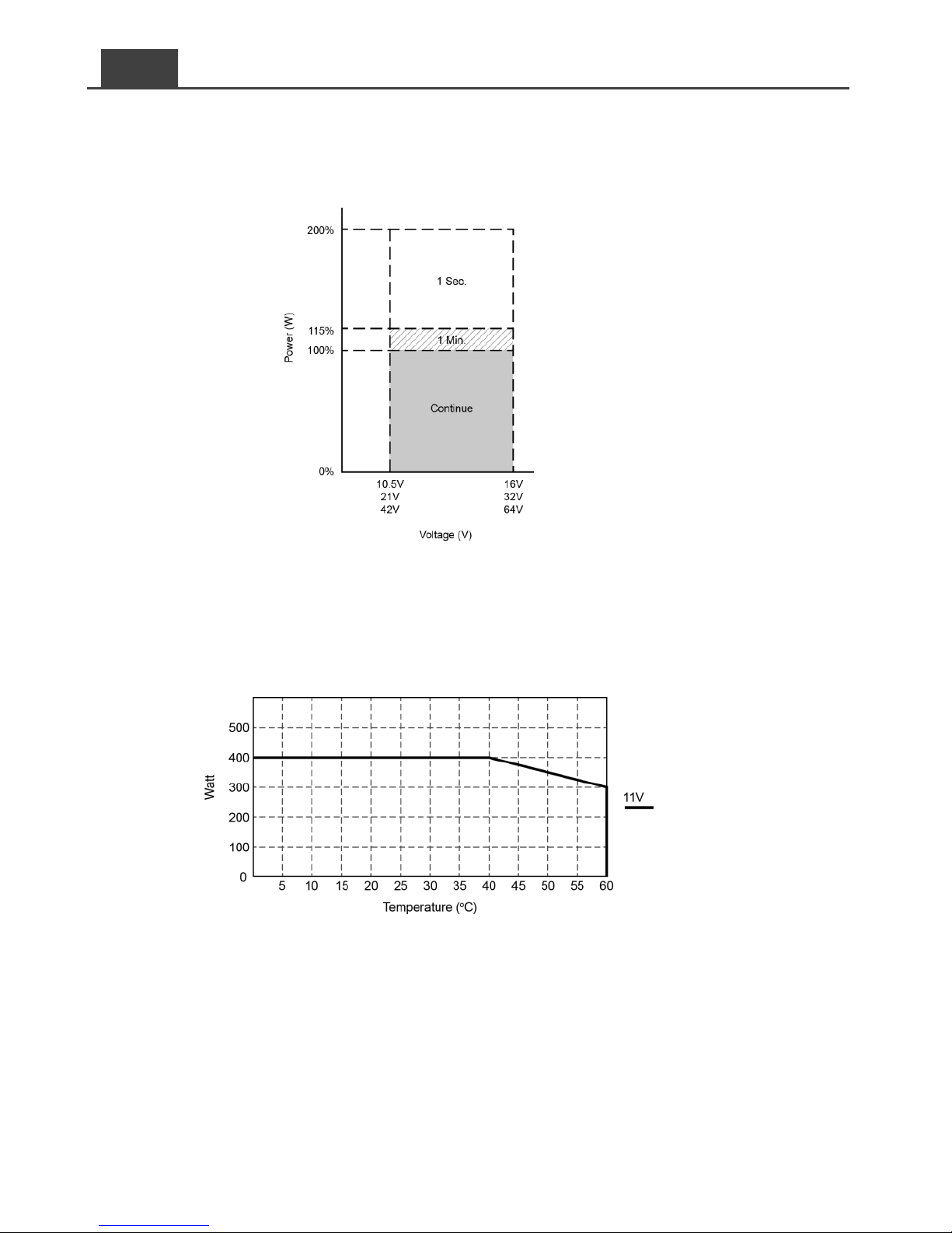
2-3-6. SE400 – Efficacité / Tension – Performances / Température
Sché ma 2. SE400 – Efficacité en fonction de la tension
Sché ma 3. SE400 – Courbe de déclassement en fonction de la température
Page 43
39
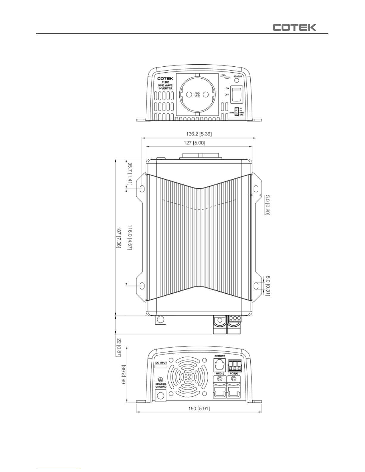
2-4. Schémas d’encombrement
Sché ma 4. Onduleurs série SE – Schémas d’encombrement
Page 44
40
FR
3. Installation et maintenance
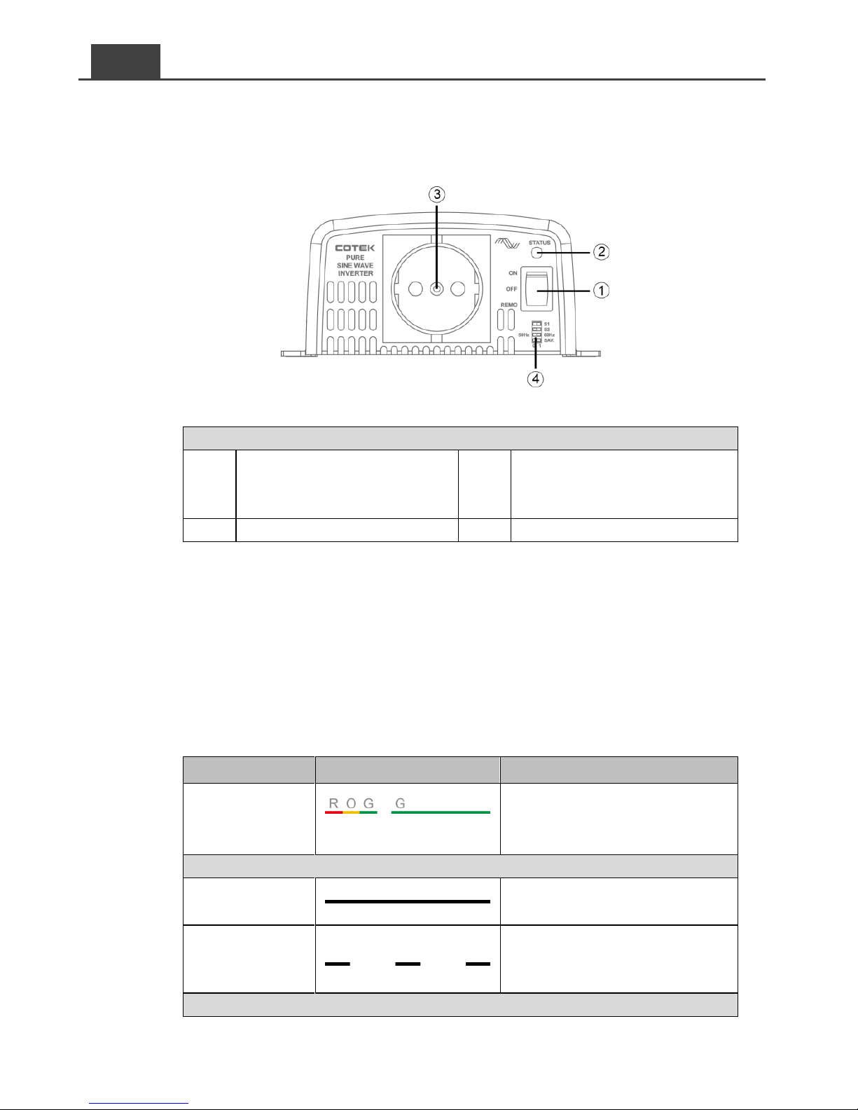
3-1. Panneau avant
Sché ma 5. Onduleurs série SE – Vue du panneau avant
Onduleurs série SE – Description du panneau avant
Interrupteur ON/OFF/REMO
(Marche / Arrêt / Commande à
distance)
Sortie CA
Témoin de fonctionnement à LED
Interrupteurs DIP (fonctions)
Tableau 6. Onduleurs série SE – Pré sentation du panneau avant
3-1-1. Interrupteur On/Off/Remote (Marche/Arrêt/Commande à distance)
Interrupteur 3 positions : Marche/Arrêt ou utilisation via la commande à
distance.
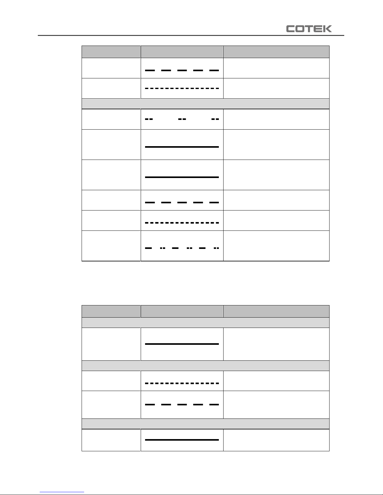
3-1-2. Témoin de fonctionnement à LED
Modèles SE200 / SE350
État
Signal
Description
En
fonctionnement
R=rouge, O=orange, G=vert
2 bips, rouge orange vert
vert
Vert
Normal
Vert
Mode
économie
d’énergie
Flashs verts lents toutes les 2
secondes
Orange
Page 45
41
État
Signal
Description
Alarme tension
basse batterie
Flashs orange lents et 5 bips
courts toutes les 15 secondes.
Alarme tension
haute batterie
Flashs orange rapides toutes
les 0.1 secondes.
Rouge
Surchauffe
Flashs rouges rapides toutes
les 1.6 secondes.
Court-circuit
sortie CA
Rouge; 2 bips courts. Coupure
au bout de 2 secondes.
3 tentatives de réarmement.
Surcharge
sortie CA
Rouge; 2 bips courts. Coupure
au bout de 3 minutes.
3 tentatives de réarmement.
Sécurité
tension basse
Flashs rouges rapides toutes
les 0.4 secondes puis coupure.
Sécurité
surcharge
Flashs rouges rapides toutes
les 0.1 secondes puis coupure.
Alarme
ventilateur
1 flash lent suivi de 2 flash
rapides rouges toutes les
1.6 secondes.
Tableau 7. Témoin à LED – Modèles SE200, SE350
Modèle SE400
État
Signal
Description
Vert
En
fonctionnement
ou normal
Témoin stable, allumé en vert.
Orange
Surcharge
Flashs orange rapides et
2 bips longs.
Surchauffe/Gel
(Temp. dissipateur
> 80°C ou < -20°C
Flashs orange lents.
Rouge
Surintensité/
Surcharge
Témoin stable allumé en rouge
et 1 bip court.
Page 46
42
FR
État
Signal
Description
(court- circuit /
surcharge sortie CA))
Tension haute
batterie
Flashs rouges rapides.
Tension basse
batterie
Flashs rouges lents, 1 bip long
et 2 bips courts.
Tableau 8. Témoin à LED – Modèle SE400
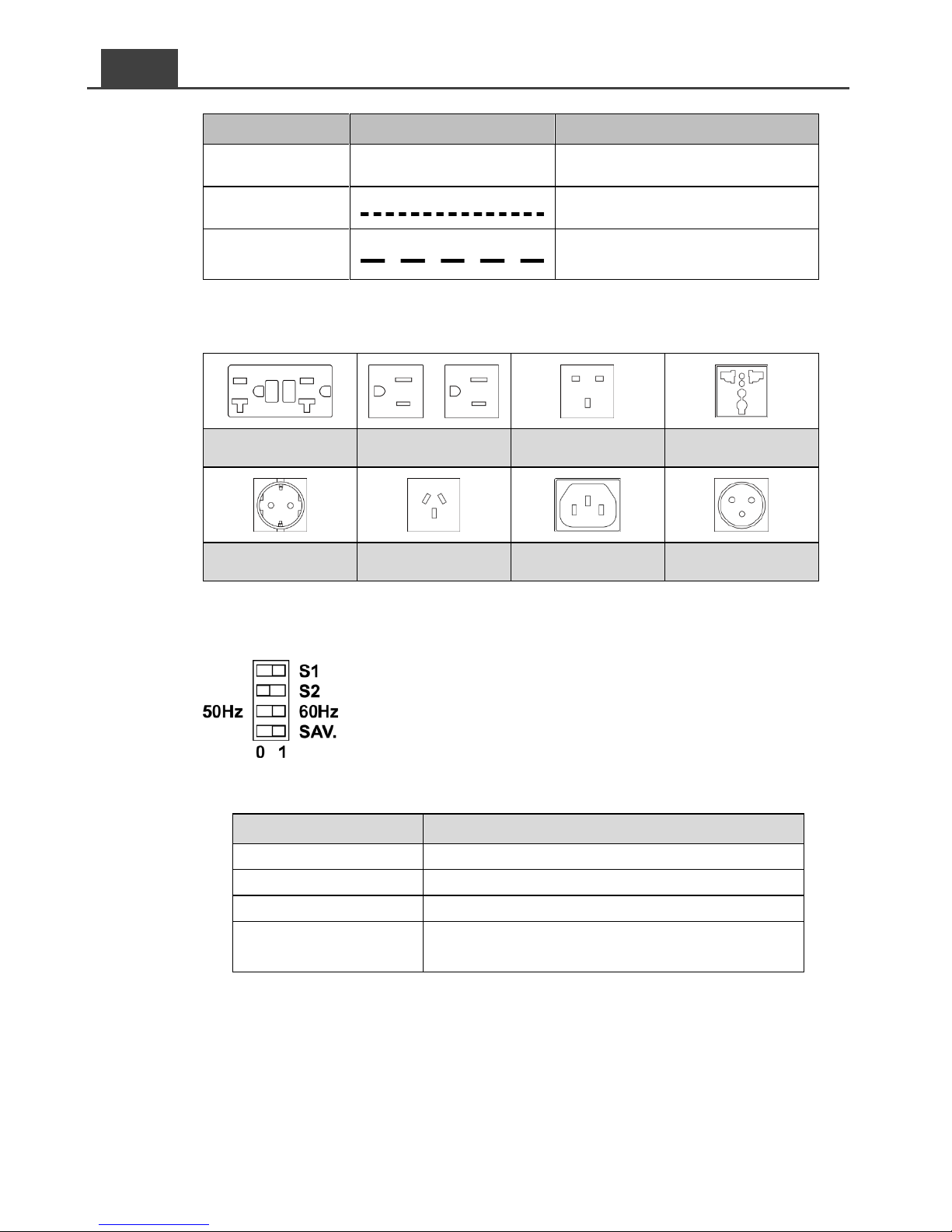
3-1-3. Socles de sorties CA
Amérique du Nord
(GFCI)
Amérique du Nord
(NEMA 5-15R)
Royaume-Uni
Universelle
Europe continentale
(Schuko)
Australie /
Nouvelle-Zélande
IEC (SE350
uniquement)
France (SE350
uniquement)
Tableau 9. Socles de sortie CA
3-1-4. Interrupteurs DIP
Schéma 6. Onduleurs série SE – Interrupteurs DIP
3-1-4-1. Fonction des interrupteurs DIP
Interrupteur DIP
Fonction
S1
Choix de la tension
S2
Choix de la tension
S3
Choix de la fréquence
S4
Activation/Désactivation du mode
économie d’énergie
Tableau 10. Onduleurs sé rie SE – Fonction des interrupteurs DIP
Page 47
43
3-1-4-2. Choix de la tension (S1 & S2)
Tension de sortie
S1
S2
100 V CA / 200 V CA
0 0 110 V CA / 220 V CA
0 1 115 V CA / 230 V CA
1
0
120 V CA / 240 V CA
1
1
Tableau 11. Onduleurs sé rie SE – Choix de la tension de sortie
Note:
Sélectionner 100/110/115/120 VAC pour les modèles 100V ou
200/220/230/240 VAC pour les modèles 200V.
3-1-4-3. Choix de la fréquence
Fréquence
50 Hz – 60 Hz
50 Hz
0
60 Hz
1
Tableau 12. Onduleurs sé rie SE – Choix de la fré quence
3-1-4-4. Mode économie d’énergie
Mode économie d’énergie
SAV.
ON
1
OFF
0
Tableau13. Onduleurs série SE – Activation/Désactivation du mode économie d’énergie
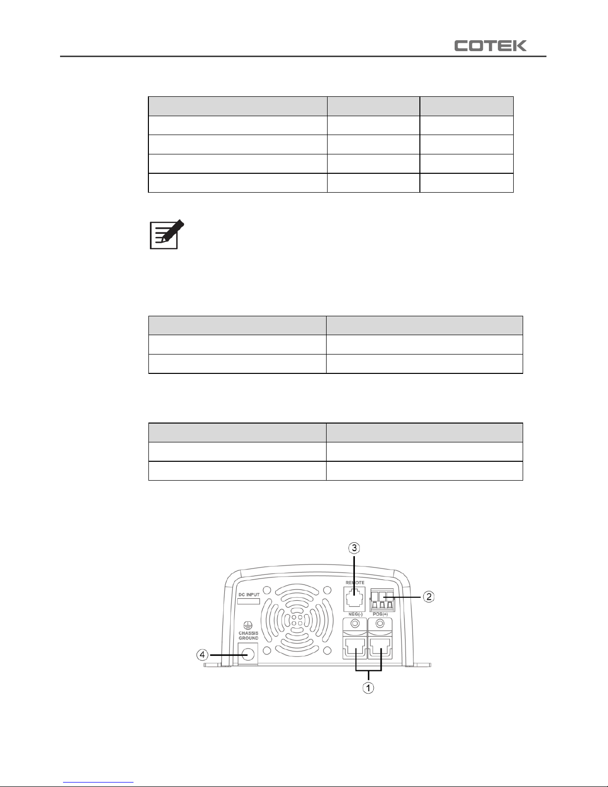
3-2. Panneau arrière
Sché ma 7. Onduleurs série SE –Vue du panneau arriè re
Page 48
44
FR
Onduleurs série SE – Description du panneau arrière
Bornes d'alimentation CC
Bornier ON/OFF pour commande à distance
Port connexion du panneau de commande à distance « REMOTE »
Borne de masse « CHASSIS GROUND »
Tableau 15. Onduleurs sé rie SE – Pré sentation du panneau arrière
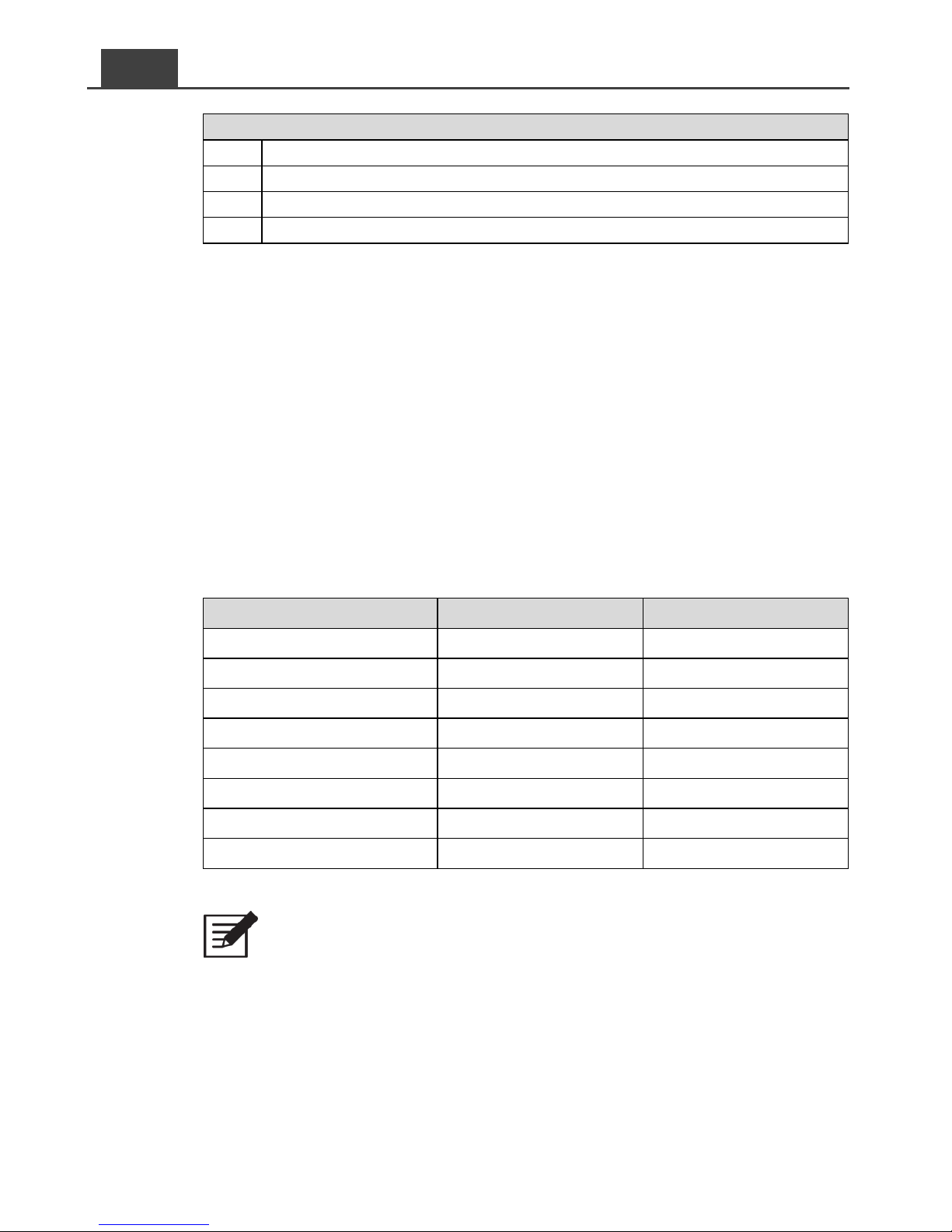
3-2-1. Bornes d'alimentation CC
Les câbles doivent être le plus court possible, idéalement d’une longueur
inférieure à 1,80 m (6 ft).
La section des câbles doit garantir que les chutes de tension restent
inférieures à 2% du courant nominal afin de prévenir les risques d’alarmes
et de coupures tension basse répétées.
Respecter les préconisations du tableau suivant pour la connexion de
l’onduleur aux batteries. Ces valeurs sont données pour des câbles d’une
longueur inférieure à 1,80 m (6 ft).
Onduleur
Section des câbles
Calibre du fusible
SE200-112 / 212
#10 – 6 mm²
≥ 30 A
SE200-124 / 224
#14 – 2.5 mm²
≥ 15 A
SE350-112 / 212
#8 – 10 mm²
≥ 50 A
SE350-124 / 224
#10 – 6 mm²
≥ 25 A
SE350-148 / 248
#14 – 2.5 mm²
≥ 12.5 A
SE400-112 / 212
#10 – 6 mm²
≥ 60 A
SE400-124 / 224
#14 – 2.5 mm²
≥ 30 A
SE400-148 / 248
#18 – 0.75 mm²
≥ 15 A
Tableau 16. Onduleurs sé rie SE – Section des câ bles CC & calibre du fusible
Note:
Les batteries peuvent générer des courants de courts-circuits forts. Monter
le fusible au plus près possible de la borne positive. Utiliser un fusible type
Bussmann ANN ou équivalent.
Page 49
45
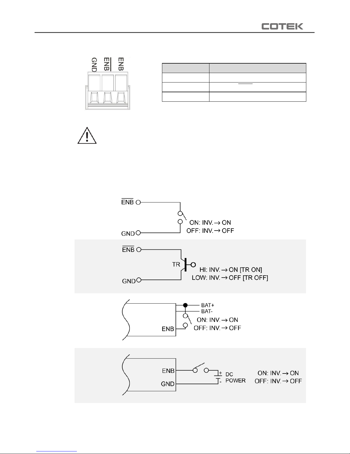
3-2-2. Bornier vert (Remote ON/OFF)
Sché ma 8 - Onduleurs série SE – Bornier vert
Attention !
Merci de respecter les consignes suivantes.
Avant d’utiliser la commande à distance, s’assurer que l’interrupteur est
bien en position « REMOTE » (Remote = commande déportée).
S’assurer que la commande à distance n’est pas activée (OFF).
Utiliser du câble 0,75 mm² entre le bornier vert et une commande.
Mode 1
Mode 2
Mode 3
Mode 4
Tableau 18 - Onduleurs série SE – Options de câblage de la commande à distance
Item
Description
1
GND
2
Enable (ENB) Remote OFF
3
Enable (ENB) Remote ON
Tableau 17. Onduleurs sé rie SE – Description du bornier vert
Page 50
46
FR
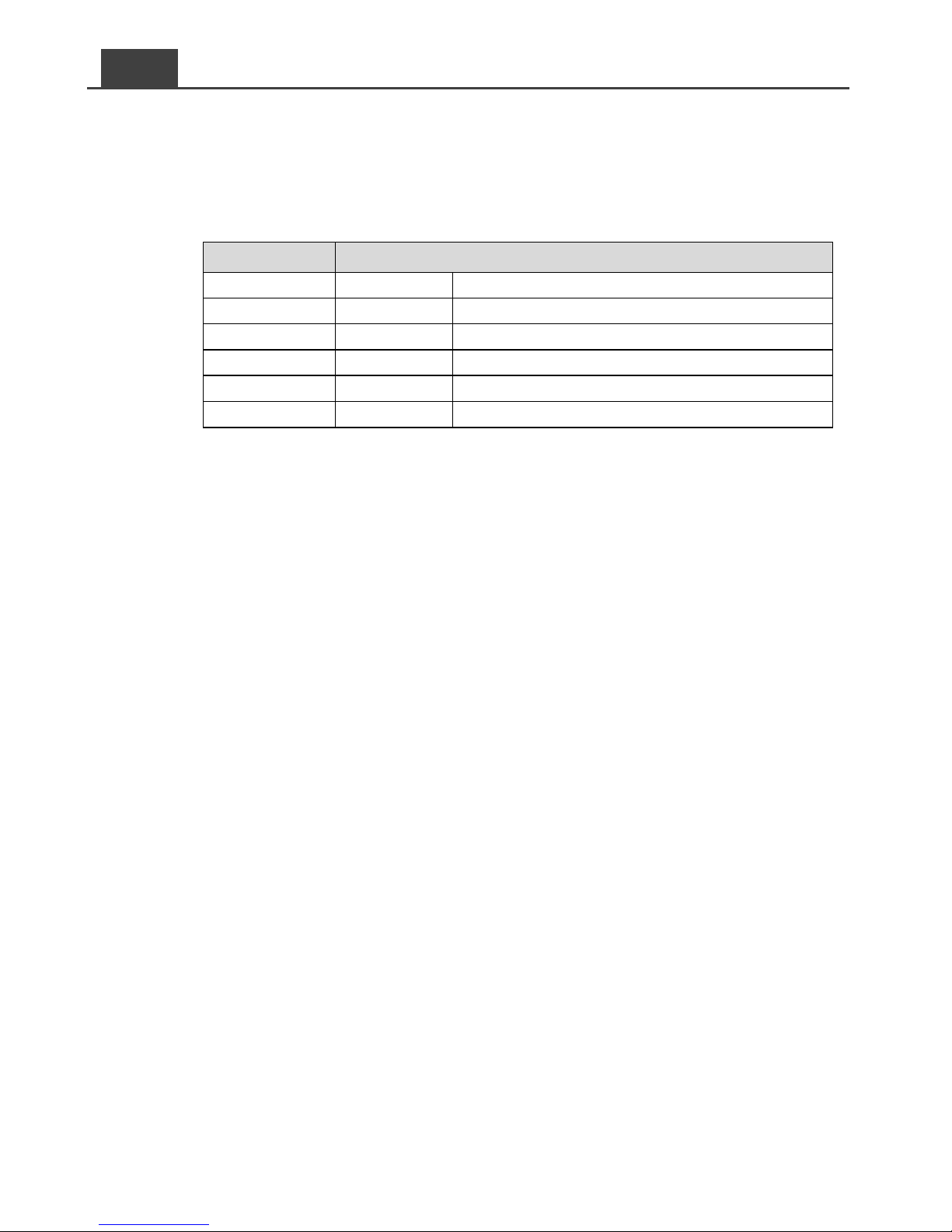
3-2-3. Port « REMOTE » (RJ-11)
Port de connexion type RJ-11 pour le branchement de la commande à
distance modèle CR-8. Avant d’utiliser la commande déportée, s’assurer
que l’interrupteur principal sur l’onduleur est bien en position « REMOTE ».
Broche
Signal
1
Réservé
─
2
GND
Négatif 3 ─ ─ 4
─ ─ 5
RMT
Positif 6 ─
─
Tableau 19. Onduleurs série SE –Port RJ-11
3-2-4. Borne de masse ("CHASSIS GROUND")
La liaison à la masse s’effectue à l’aide d’un câble reliant le boîtier de
l'onduleur au châssis du véhicule.
3-3. Entretien
Vérifier que les pales du ventilateur de refroidissement ne sont pas
obstruées.
Utiliser un aspirateur pour extraire la poussière autour du ventilateur.
Utiliser un chiffon doux et sec pour essuyer le boîtier de l’onduleur. S’il est
nécessaire de nettoyer le panneau avant, utiliser un chiffon humide et du
savon neutre. Ne pas utiliser de produit à base d’alcool ou d’ammoniaque.
Éviter de répandre du liquide sur l’onduleur.
Les interventions de maintenance ou le déplacement de l’onduleur doivent
être effectués par un technicien qualifié.
Page 51
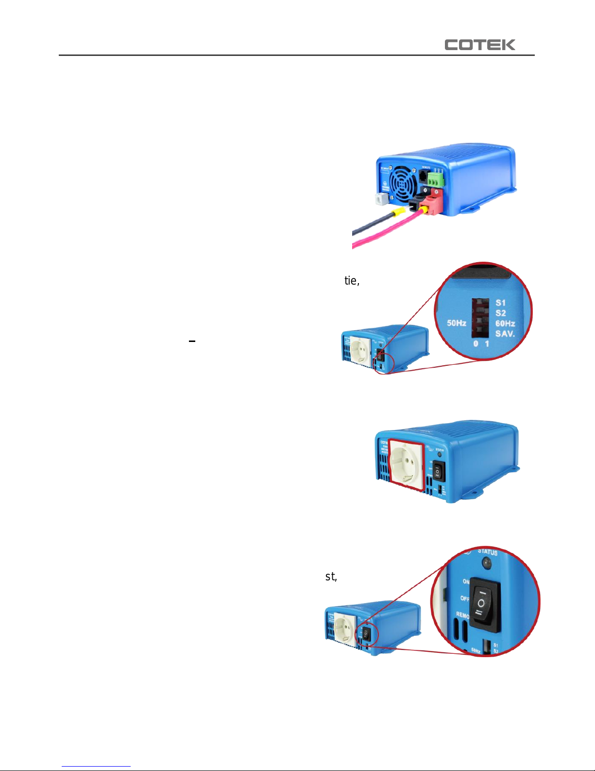
47
3-4. Installation et mise en service
Avant d’installer l’onduleur, placer l’interrupteur principal sur « OFF ».
Étape 1
Raccorder les câbles d’alimentation CC à
l’onduleur puis à la batterie, en prenant
soin de respecter les polarités.
Étape 2
Paramétrer la tension et la fréquence de sortie,
ainsi que le mode économie d’énergie
via les interrupteurs DIP.
(Voir § 3-1-4.)
Étape 3
Raccorder le consommateur à
la sortie CA.
Étape 4
Mettre l’onduleur sous tension (ON).
Le buzzer émet des bips durant l’auto-test,
et la LED d’état s’allume de
différentes couleurs.
Au final, le buzzer émet un
dernier bip et la LED s’allume en vert,
indiquant que l’onduleur est sous tension
et qu’il fonctionne normalement.
Sché ma 9. Installation – Étape 1
Sché ma 10. Installation – Étape 2
Sché ma 11. Installation – Étape 3
Sché ma 12. Installation – Étape 4
Page 52
48
FR
Note:
3. Si plusieurs consommateurs sont raccordés à l’onduleur, les mettre sous tension
l’un après l’autre, pour prévenir les risques de surcharge liés à l’appel de
courant.
4. Pour mesurer la vraie valeur efficace de la tension délivrée, utiliser un multimètre
RMS type Fluke 45, Beckman 4410 ou Triplet 4200.
4. Utilisation
4.1. Connexion aux bornes d’alimentation CC
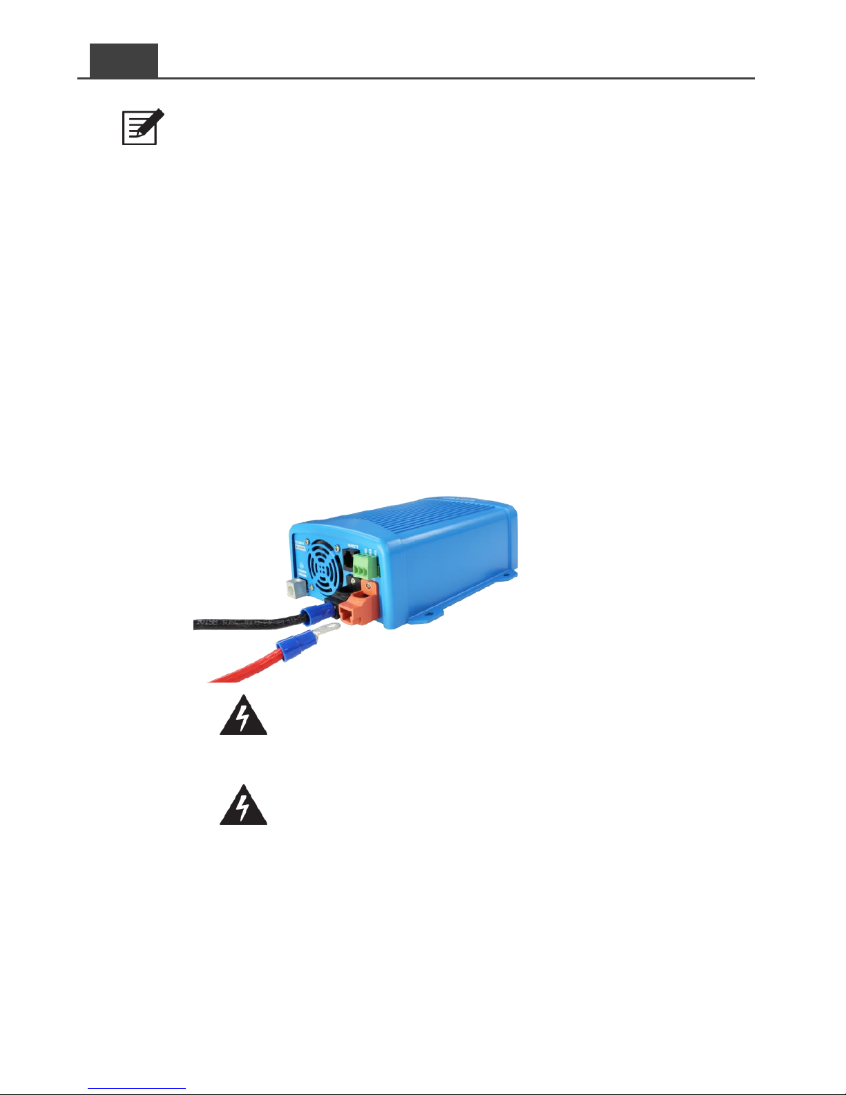
Raccorder les bornes d’entrée CC à une batterie 12V / 24V / 48V ou à autre
source courant continu. [ + ] est la borne positive et [ - ] la borne négative.
Inverser les polarités ferait sauter le fusible interne et endommagerait
l’onduleur de manière irréversible.
Sché ma 13. Connexion alimentation CC
Attention ! Toutes les connexions CC doivent être
correctement serrées au risque de provoquer une surchauffe
et des risques potentiels. Serrer à 9-10 ft-lbs, 11.7-13 Nm
Attention ! Protéger l’installation en montant un fusible en
ligne le plus près possible de la borne positive. Le
non-respect de cette consigne risque de provoquer des
dommages (câble / onduleur) et entraîne l’annulation de la
garantie.
Utiliser des câbles cuivre de qualité supérieure et les maintenir le plus
court possible (longueur maximale : 0.90-1.80 m ; 3-6 ft).
Page 53
49
4.2. Connexion à la source CC
Avant d’effectuer les branchements à la source, placer l’interrupteur
principal sur l’onduleur en position « OFF ».
4.3. Connexion des consommateurs
Calculer la charge totale des consommateurs. Elle ne doit pas dépasser la
capacité nominale de l’onduleur.
Si toutefois elle la dépasse, déconnecter les consommateurs non
nécessaires jusqu’à ce que la charge totale soit dans les limites
admissibles de l’onduleur.
4.4. Mise sous tension
Placer l’interrupteur sur « ON ». Au démarrage, l’onduleur effectue un
auto-test durant lequel le témoin à LED s’allume de différentes couleurs. À
l’issue de l’auto-test, le témoin indique le statut de l’onduleur.
4.5. Protections
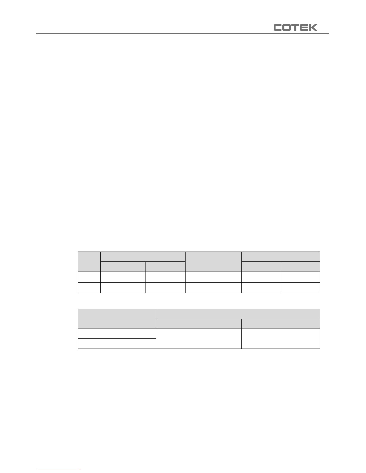
4-5-1. SE200
V
Tension haute (DC)
Alarme tension
basse
Tension basse
Coupure
Reprise
Coupure
Reprise
12V
16V ± 3%
14.5V± 3%
10.5V ± 3%
10.0V ± 3%
12.5V ± 3%
24V
32V ± 3%
29V ± 3%
21V± 3%
20V ± 3%
25V ± 3%
Tableau 20. SE200 – Protections entré e CC
V
Protection surchauffe
Coupure
Reprise
12V
90°C ± 3°C
50°C ± 3°C
24V
Tableau 21. SE200 – Protection surchauffe
Page 54
50
FR
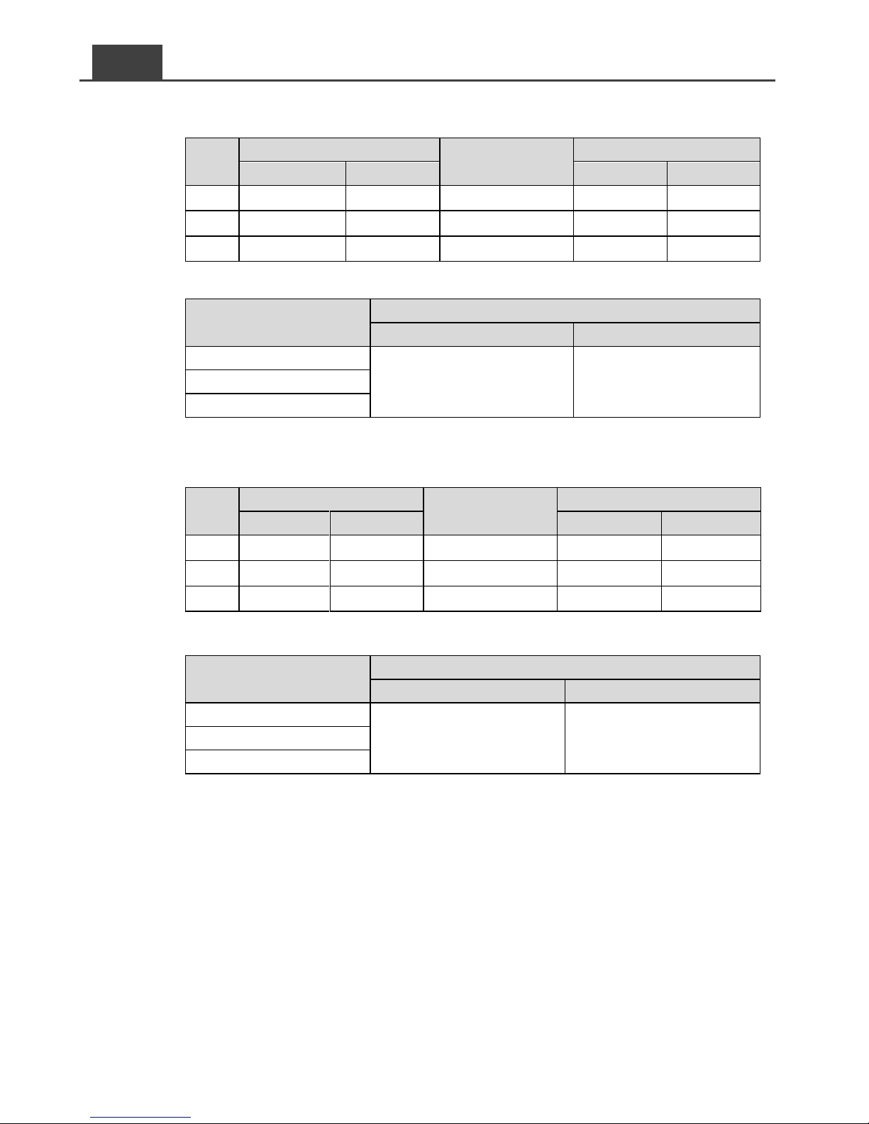
4-5-2. SE350
V
Tension haute (DC)
Alarme tension
basse
Tension basse
Coupure
Reprise
Coupure
Reprise
12V
15.5V ± 0.25V
14.5V± 0.25V
10.5V ± 0.25V
10V ± 0.25V
12V± 0.25V
24V
31V ± 0.5V
29V ± 0.5V
21V± 0.5V
20V ± 0.5V
24V ± 0.5V
48V
62 ± 1V
58V ± 1V
42V± 1V
40V ± 1V
48 ± 1V
Tableau 22. SE350 – Protections entré e CC
V
Protection surchauffe
Coupure
Reprise
12V
83°C ± 5°C
53°C ± 5°C
24V
48V
Tableau 23. SE350 – Protection surchauffe
4-5-3. SE400
V
Tension haute (DC)
Alarme tension
basse
Tension basse
Coupure
Reprise
Coupure
Reprise
12V
16V ± 0.3V
14.5V± 0.3V
10.5V ± 0.3V
10.5V ± 0.3V
12.5V± 0.3V
24V
32V ± 0.5V
29V ± 0.5V
21V± 0.5V
21V ± 0.5V
25V ± 0.5V
48V
64 ± 1V
58V ± 1V
42V± 1V
42V ± 1V
50 ± 1V
Tableau 24. SE400 – Protections entré e CC
V
Protection surchauffe
Coupure
Reprise
12V
80°C
60°C
24V
48V
Tableau 25. SE400 – Protection surchauffe
Page 55
51
4.6. Guide de dépannage
Attention !
Ne pas ouvrir ni démonter l’onduleur. Une tentative d’intervention peut
entraîner des risques de chocs électriques voire un incendie.
SE200 / SE350
Signal LED
Description
Solutions
Flashs orange lents avec 5 bips
courts toutes les 15 secondes
Alarme tension
basse
Vérifier les branchements et
l’état des connexions.
Recharger la batterie.
Flashs orange rapides toutes
les 0.1 secondes
Tension haute
Vérifier la tension d’entrée. Elle
doit être dans les limites
admissibles de l’onduleur.
Rouge stable plus 2 bips courts.
Coupure au bout de 3 minutes.
3 tentatives de reprise
Protection
surcharge
(sortie CA)
Réduire la charge.
En cas d’échec au
redémarrage, remettre
manuellement sous tension.
Rouge stable plus 2 bips courts.
Coupure au bout de 3 minutes.
3 tentatives de reprise
Protection
court-circuit
(sortie CA)
Identifier la cause du
court-circuit et corriger.
En cas d’échec au
redémarrage, remettre
manuellement sous tension.
Flashs rouges rapides toutes les
1.6 secondes
Surchauffe
Vérifier l’état du ventilateur et
améliorer la ventilation. Faire
baisser la température
ambiante.
Flashs rouges rapides toutes les
0.4 secondes puis coupure
Coupure tension
basse
Vérifier l’état des connexions
et des câbles. Recharger la
batterie. Remettre
manuellement sous tension.
Flashs rouges rapides toutes les
0.1 secondes puis coupure
Coupure tension
haute
Vérifier la tension d’entrée. La
réduire. Remettre
manuellement sous tension.
1 flash rouge lent et 2 flashs
rapides toutes les 1.6 secondes
Alarme
ventilateur de
refroidissement
Vérifier les branchements.
Nettoyer les pales du
ventilateur.
Tableau 26. Onduleurs SE200 / SE350 – Guide de dépannage
Page 56
52
FR
SE400
Signal LED
Description
Solutions
Flashs rapides orange et 2 bips
longs
Surcharge
400W 460W
(100% 115%)
Réduire la charge.
En cas d’échec au
redémarrage, remettre
manuellement sous tension.
Flashs orange lents
Surchauffe /
Gel
Améliorer la ventilation.
Vérifier que les grilles ne sont
pas obstruées. Faire baisser la
température ambiante /
attendre qu’elle remonte.
Rouge stable et un bip court
Surintensité
Surcharge
>460W (115%)
Réduire la charge.
En cas d’échec au
redémarrage, remettre
manuellement sous tension.
Flashs rouges rapides
Tension haute
Vérifier la tension
d’alimentation CC. La ramener
la tension d’entrée dans les
limites admissibles.
Flashs rouges lents plus 1 bip
long et 2 bips courts
Tension basse
Recharger la batterie. Vérifier
les branchements. Remettre
sous tension manuellement.
Tableau 27. Onduleur SE400 – Guide de dé pannage
Page 57

53
5. Garantie
5-1 Attention
Attention !
Ne pas ouvrir ni démonter l’onduleur. Risques de choc électrique
ou d’incendie.
5-2 Garantie
Nous garantissons ce produit contre tout défaut de matériaux et
de main-d’œuvre pour une durée de 24 mois. Pour toute demande
de service après-vente, merci de contacter votre distributeur local
COTEK.
Cette garantie sera considérée comme nulle si l’appareil n’a pas
été utilisé de manière correcte, s’il a été modifié ou s’il a été
endommagé accidentellement. COTEK ne saurait être tenu
responsable de dommages résultant d’une faute de l’utilisateur.
Page 58

No.33, Sec. 2, Renhe Rd., Daxi Dist., Taoyuan City 33548, Taiwan
Phone:+886-3-3891999 FAX:+886-3-3802333
http:// www.cotek.com.tw
2018.06._A0
 Loading...