

Page 1

SD Series User’s Manual
SD2500 / SD3500
PURE SINE WAVE INVERTER
Page 2

Legal Provisions
Copyrights 2016 COTEK Electronic IND. CO. All Rights Reserved.
Any part of this document may not be reproduced in any form for any purpose without the prior
written permission of COTEK Electronic IND. CO. For the conditions of the permission to use this
manual for publication, contact COTEK Electronic IND. CO., LTD. In all related COTEK product
activities, Neither COTEK Electronic IND. CO., LTD. nor its distributors or dealers be liable to
anyone for indirect, incidental, or consequential damages under any circumstances. Specifications
are subject to change without notice. Every attempt has been made to make this document
complete, accurate and up-to-date. COTEK Electronic IND. CO., LTD reserve the right to make
changes without notice and shall not be responsible for any damages, including indirect, incidental
or consequential damages, caused by reliance on the material presented, including, but not limited
to, omissions, typographical errors, arithmetical errors or listing errors in the content material. All
trademarks are recognized even if these are not marked separately. Missing designations do not
mean that a product or brand is not a registered trademark.
Page 3

Table of Content
1. IMPORTANT SAFETY INFORMATION 1
1-1. General Safety Precautions 1
1-2. Precautions When Working with Batteries 1
1-3. Installation 2
2. FUNCTIONAL CHARACTERISTICS 3
2-1. General Information 3
2-2. Application 3
2-3. Electrical Performance 4
2-4. Mechanical Drawings 8
3. INTRODUCTION 9
3-1. Power ON / OFF / REMOTE (Main) switch 10
3-2. LED Indicator 10
3-3. DIP Switch (S1~S8) Assignment 11
3-4. DC Input - 12
3-5. DC Input + 13
3-6. Chassis Ground 13
3-7. AC Output 13
3-8. By-pass AC input 13
3-9. AC input circuit breaker 13
3-10. AC output socket 13
3-11. Reset Button 13
3-12. CAN1 and CAN2 Port 13
3-13. LCM Port 14
3-14. Green terminal 15
3-15. RS-232 Port 15
3-16. Fan Ventilation 16
3-17. Protections Features 16
Page 4

4. DC WIRING CONNECTIONS 17
4-1. DC Input Terminals 18
4-2. Hard-wire Installation 19
5. PARALLEL MODE 24
5-1. Prepare for Parallel Usage 24
5-2. Industry Applications 25
5-3. DC Wiring for Parallel Usage 27
5-4. AC Wiring Diagram 29
5-5. Remote command for the parallel connection 33
5-6. Remove Parallel Connection 33
6. RS-232 COMMAND 34
6-1. RS-232 command introduction 34
7. TROUBLESHOOTING 42
8. WARRANTY 42
Page 5

1.Important Safety Information
WARNING!
Before using the inverter, read and save the safety instructions.
1-1. General Safety Precautions
1-1-1. Do not expose the Inverter to rain, snow, spray, bilge or dust.
To reduce risk of hazard, do not cover or obstruct the ventilation openings. Do
not install the inverter in a zero-clearance compartment. Overheating may
take place.
1-1-2. To avoid a risk of fire and electric shock, please make sure that existing wiring
is in good electrical condition; and that wire size is not undersized. Do not
operate the Inverter with damaged or substandard wiring.
1-1-3. This equipment contains components which can produce arcs or sparks.
1. Important Safety Information
To prevent fire or explosion do not install in compartments containing batteries
or flammable materials or in locations which require ignition protected
equipment. This includes any space containing gasoline-powered machinery,
fuel tanks, joints, fittings, or other connection between components of the fuel
system.
1-1-4. An over current protection at the time of installation shall be provided by
others for the AC output circuit.
1-1-5. Additional breakers suitable for 20 A branch circuit protection shall be
provided for the GFCI receptacles.
1-2. Precautions When Working with Batteries
1-2-1. If battery acid contacts skin or clothing, wash immediately with soap and water.
If acid enters eye, immediately wash eyes with running cold water for at least
20 minutes and get medical attention immediately.
1-2-2. Never smoke or allow a spark or flame in vicinity of battery or engine.
1-2-3. Do not drop a metal tool on the battery. The resulting spark or short-circuit on
the battery or other electrical part may cause an explosion.
1-2-4. Remove personal metal items such as rings, bracelets, necklaces, and
watches when working with a lead-acid battery.
A lead-acid battery produces a short-circuit current high enough to weld a ring
or similar item to metal causing a severe burn.
1
Page 6
1-3. Installation
The power inverter should be installed in a location that meets the following
requirements
Dry – Do not allow water to drip or splash on the inverter.
Cool – Ambient air temperature should be between -20 and 50 , but he cooler
the better.
Safety – Do not install batteries in the compartment or other areas here flammable
fumes existence such as fuel storage areas or engine compartments.
Ventilated – Allow at least one feet of clearance around the Inverter for air flow.
Ensure the ventilation shafts on the rear and bottom of the unit are not
obstructed.
Dust-free – Do not install the Inverter in dusty environments here dust, wood
particles or other filings/shavings are present. The dust can be pulled
into the unit when the cooling fan is in operation.
Close to batteries – Avoid excessive cable lengths but do not install the inverter in
the same compartment as batteries.
Use the recommended wire lengths and sizes (refer to section 4.DC wiring
connections).
Do not mount the inverter where it is exposed to the gases produced by the battery.
These gases are very corrosive and prolonged exposure will damage the inverter.
WARNING!
Shock Hazard. Before proceeding further, carefully check that the inverter is
NOT connected to any batteries, and that all wiring is disconnected from any
electrical sources . Do not connect the output terminals of the inverter to an
incoming AC source.
2
Page 7

2.Functional Characteristics
2-1. General Information
SD-series is new generation power inverter equipped with N+1 parallel power
function , 3-phase capability, and AC transfer switch. SD series is suitable for RV,
Marine and Emergency appliances.
Features
z Parallel redundancy design for power expansion
z Multiple industrial applications that create 1Ф3W / 3Ф4W power systems
z User-friendly remote control
z Automatic master mechanism to eliminate single point failure and optimize
reliability
z Built-in ATS and AC circuit breaker
z Optional STS module, transfer time is less than 4ms.
2. Functional Characteristics
z RS-232 communication
z Input & output fully isolation
z Output voltage / power saving mode is selectable by DIP switch and remote
control (CR-10)
z Input Protection Reverse Polarity (Fuse) / Under Voltage / Over Voltage
Protection
z Output Protection Short Circuit / Overload / Over Temperature / Over Voltage
Protection
To get the most out of the power inverter, it must be installed and used properly.
Please read the instructions in this manual before installation and operation of this
model.
2-2. Application
2-2-1. Power tools–circular saws, drills, grinders, sanders, buffers, weed and hedge
trimmers, air compressors.
2-2-2. Office equipment – computers, printers, monitors, facsimile machines,
scanners.
2-2-3. Household items – vacuum cleaners, fans, fluorescent and incandescent
lights, shavers, sewing machines.
2-2-4. Kitchen appliances – coffee makers, blenders, ice markers, toasters.
2-2-5. Industrial equipment – metal halide lamp, high pressure sodium lamp.
2-2-6. Home entertainment electronics – television, VCRs, video games, stereos,
musical instruments, satellite equipment.
2-2-7. Vehicle, yacht and off-grid solar power systems.
3
Page 8
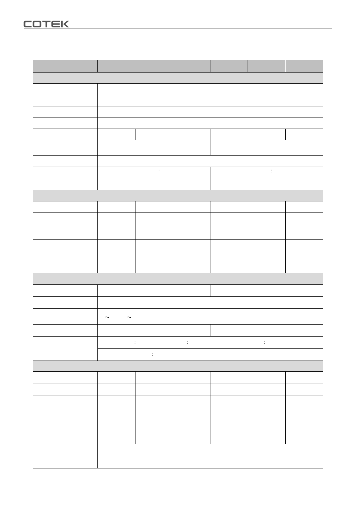
2-3. Electrical Performance
2-3-1. SD2500 Specification
MODEL SD2500-112 SD2500-124 SD2500-148 SD2500-212 SD2500-224 SD2500-248
Output
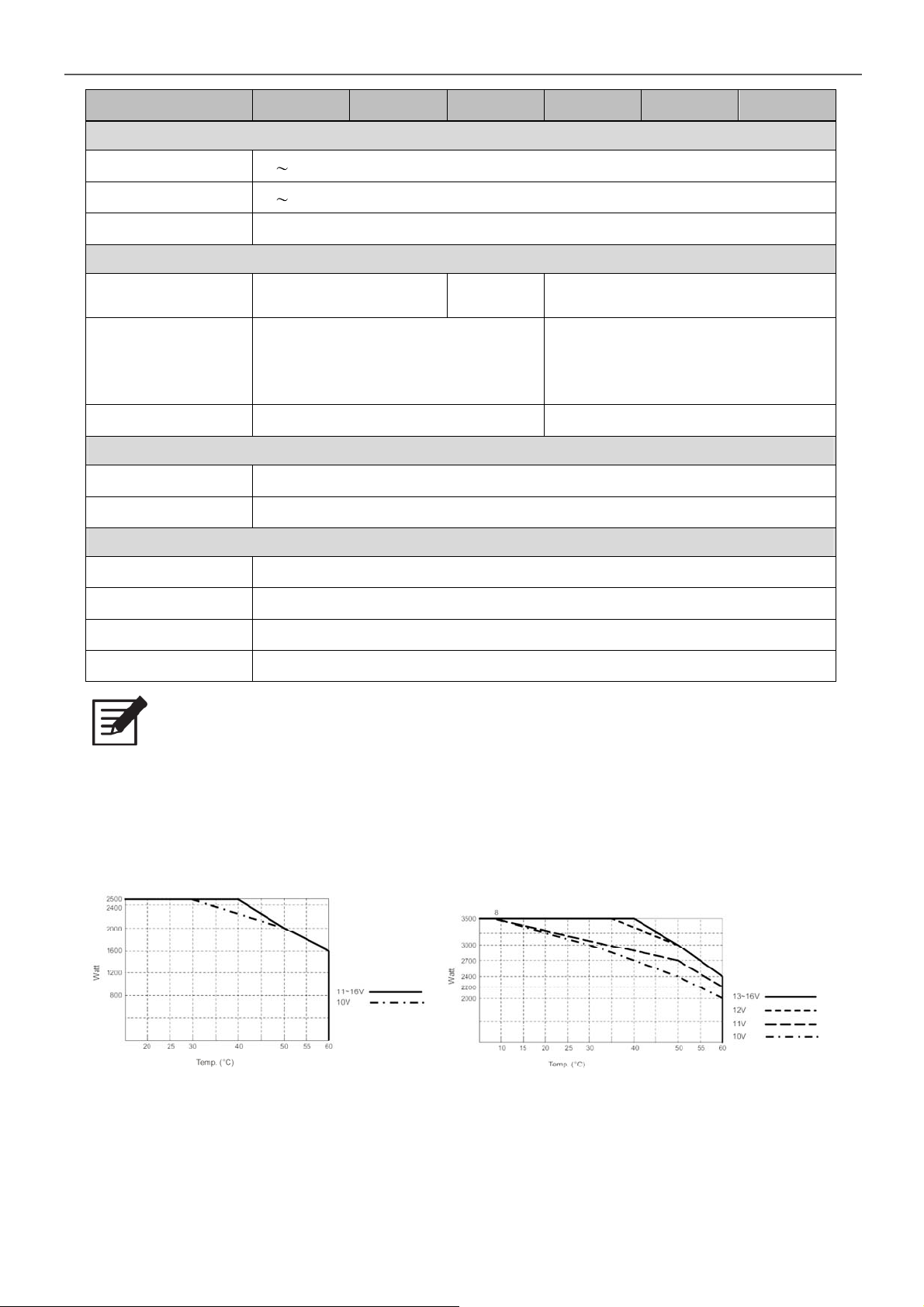
Rating Power 2500W (de-rating after 40°C, refer to de-rating curve)
Peak Power (3Sec.) 3000W
Surge Power (<0.2Sec.) 4000W
Waveform Pure Sine Wave
Efficiency (Max.) 88% 89% 90% 88% 88% 90%
Output Voltage
(@rated VDC)
Output Frequency 50 / 60Hz ± 0.1%
Total Harmonic
Distortion (THD)
DC Voltage 12VDC 24VDC 48VDC 12VDC 24VDC 48VDC
< 3% @ under condition
greater than 1.15 times of the rated VDC,
110V / linear load)
100 / 110 / 115 / 120VAC ± 3% 200 / 220 / 230 / 240VAC ± 3%
< 3% @ under condition
greater than 1.15 times of the rated VDC,
230V / linear load)
DC Input
Voltage Range 10.0~16.0 VDC 20.0~32.0 VDC 40.0~64.0 VDC 10.0~16.0 VDC 20.0~32.0 VDC 40.0~64.0 VDC
No load Power
Consumption
On Mode @ Save Mode 0.9A 0.35A 0.3A 1.1A 0.7A 0.4A
On Mode @ No Load Mode < 2.9A < 1.4A < 0.8A < 3.6A < 1.8A < 1A
Fuse 40Ax9 20Ax9 15Ax6 40Ax9 20Ax9 15Ax6
@12VDC @24VDC @48VDC @12VDC @24VDC @48VDC
AC Input
AC Range 100 / 110 / 115 / 120VAC ± 12.5% 200 / 220 / 230 / 240VAC ± 12.5%
Frequency Selectable 50 / 60 Hz
Synchronous
Frequency
Circuit Breaker 35A 20A
Transfer Switch
①
47
57 / 53 63 Hz
Standard ATS Inverter to utility AC 8~10ms.; Utility AC to inverter 16~50ms.
Optional STS module Single < 4ms; N+1 & 1P3W & 3P4W < 6ms
Protection
BAT.Low Alarm ± 3% 10.5VDC 21.0VDC 42.0VDC 10.5VDC 21.0VDC 42.0VDC
BAT.Low Shut-down ± 3% 10.0VDC 20.0VDC 40.0VDC 10.0VDC 20.0VDC 40.0VDC
BAT.Low Restart ± 3% 12.5VDC 25.0VDC 50.0VDC 12.5VDC 25.0VDC 50.0VDC
BAT.High Alarm ± 3% 15.5VDC 31.0VDC 62.0VDC 15.5VDC 31.0VDC 62.0VDC
BAT.High Shut-down ± 3% 16.0VDC 32.0VDC 64.0VDC 16.0VDC 32.0VDC 64.0VDC
BAT.High Restart ± 3% 15.0VDC 30.0VDC 60.0VDC 15.0VDC 30.0VDC 60.0VDC
Input Protection Reverse Polarity (Fuse) / Under Voltage / Over Voltage Protection / AC over current (Breaker)
Output Protection Short Circuit / Overload / Over Temperature / Over Voltage Protection
4
Page 9
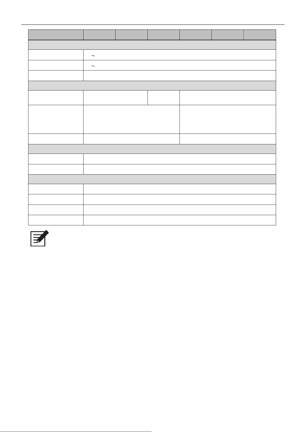
2. Functional Characteristics
MODEL SD2500-112 SD2500-124 SD2500-148 SD2500-212 SD2500-224 SD2500-248
Environment
Working Temp. -20 +60°C; refer SD2500 power de-rating curve
Storage Temp. -40 +70°C
Relative Humidity Max. 90%, non-condensing
Safety & EMC
Safety Standards
EMC Standards Certified FCC Class B
E-Mark ---- Certified CISPR 25; ISO 7637-2
LED Indicator Input voltage level, faulty status
Certified UL 458
(UL only for hardwire)
---- Certified EN60950-1
Control & Signal
②
Certified EN 55014-1, EN 55014-2;
EN 61000-3-2, -3-3; EN61204-3;
EN 61000-6-1, -6-2, -6-3, -6-4
IEC 61000-4-2, 3, 4, 5, 6, 11
Remote Control CR-6, CR-8 and CR-10
Others
Dimension (WxHxD) 283x128x436 mm / 11.14x5.04x17.17iInch
Weight 8 kg
Cooling Load & Thermal control fan
Communication Port RS-232 (RJ-11 type connector), Ethernet (Optional)
Note
The specifications are subject to change without prior notice. All the test
environments are conducted under the rated power operation conditions.
① Please refer to P.8 Transfer-Time Table.
② EN 55014-1, EN 55014-2 Class B: output cable less than 2 meters.
5
Page 10
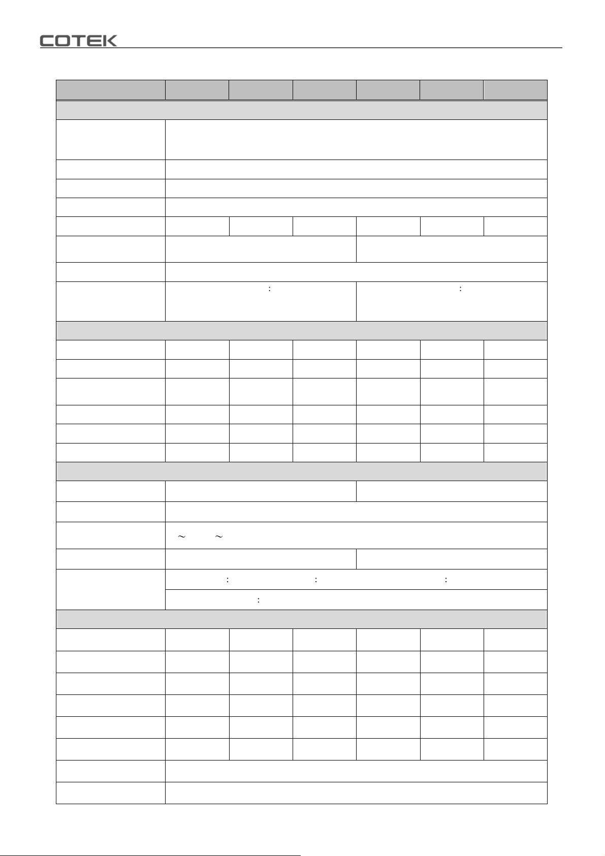
2-3-2. SD3500 Specification
MODEL SD3500-112 SD3500-124 SD3500-148 SD3500-212 SD3500-224 SD3500-248
Output
3500W
Rating Power
Peak Power (3Sec.) 4500W
Surge Power (<0.2Sec.) 6000W
Waveform Pure Sine Wave
Efficiency (Max.) 90% 90% 91% 90% 91% 91%
Output Voltage
(@rated VDC)
Output Frequency 50 / 60Hz ± 0.1%
Total Harmonic
Distortion (THD)
DC Voltage 12VDC 24VDC 48VDC 12VDC 24VDC 48VDC
(de-rating after 35°C, refer to de-rating curve for 12V)
(de-rating after 40°C, refer to de-rating curve for 24V and 48V)
100 / 110 / 115 / 120VAC ± 3% 100 / 110 / 115 / 120VAC ± 3%
< 3% @ under condition
greater than 1.15 times of the rated VDC,
110V / linear load)
< 3% @ under condition
greater than 1.15 times of the rated VDC,
110V / linear load)
DC Input
Voltage Range 10.0~16.0 VDC 20.0~32.0 VDC 40.0~64.0 VDC 10.0~16.0 VDC 20.0~32.0 VDC 40.0~64.0 VDC
No load Power
Consumption
On Mode @ Save Mode 1.4A 0.5A 0.5A 1.4A 0.5A 0.5A
On Mode @ No Load Mode < 2.9A < 1.4A < 0.8A < 3.6A < 1.8A < 1A
Fuse 40Ax12 20Ax12 20Ax6 40Ax12 20Ax12 20Ax6
@12VDC @24VDC @48VDC @12VDC @24VDC @48VDC
AC Input
AC Range 100 / 110 / 115 / 120VAC ± 12.5% 200 / 220 / 230 / 240VAC ± 12.5%
Frequency Selectable 50 / 60 Hz
Synchronous
Frequency
Circuit Breaker 35A 20A
Transfer Switch
①
57 / 53 63 Hz
47
Standard ATS Inverter to utility AC 8~10ms.; Utility AC to inverter 16~50ms.
Optional STS module Single < 4ms; N+1 & 1P3W & 3P4W < 6ms
Protection
BAT.Low Alarm ± 3% 10.5VDC 21.0VDC 42.0VDC 10.5VDC 21.0VDC 42.0VDC
BAT.Low Shut-down ± 3% 10.0VDC 20.0VDC 40.0VDC 10.0VDC 20.0VDC 40.0VDC
BAT.Low Restart ± 3% 12.5VDC 25.0VDC 50.0VDC 12.5VDC 25.0VDC 50.0VDC
BAT.High Alarm ± 3% 15.5VDC 31.0VDC 62.0VDC 15.5VDC 31.0VDC 62.0VDC
BAT.High Shut-down ± 3% 16.0VDC 32.0VDC 64.0VDC 16.0VDC 32.0VDC 64.0VDC
BAT.High Restart ± 3% 15.0VDC 30.0VDC 60.0VDC 15.0VDC 30.0VDC 60.0VDC
Input Protection Reverse Polarity (Fuse) / Under Voltage / Over Voltage Protection / AC over current (Breaker)
Output Protection Short Circuit / Overload / Over Temperature / Over Voltage Protection
6
Page 11
2. Functional Characteristics
MODEL SD3500-112 SD3500-124 SD3500-148 SD3500-212 SD3500-224 SD3500-248
Environment
Working Temp. -20 +60°C; refer SD3500 power de-rating curve
Storage Temp. -40 +70°C
Relative Humidity Max. 90%, non-condensing
Safety & EMC
Safety Standards
EMC Standards Certified FCC Class B
E-Mark ---- Certified CISPR 25; ISO 7637-2
LED Indicator Input voltage level, faulty status
Certified UL 458
(UL only for hardwire)
---- Certified EN60950-1
Control & Signal
②
Certified EN 55014-1, EN 55014-2;
EN 61000-3-2, -3-3; EN61204-3;
EN 61000-6-1, -6-2, -6-3, -6-4
IEC 61000-4-2, 3, 4, 5, 6, 11
Remote Control CR-6, CR-8 and CR-10
Others
Dimension (WxHxD) 283x128x496 mm / 11.14x5.04x19.53 inch
Weight 10 kg
Cooling Load & Thermal control fan
Communication Port RS-232 (RJ-11 type connector), Ethernet (Optional)
Note
The specifications are subject to change without prior notice. All the test
environments are conducted under the rated power operation conditions.
① Please refer to P.8 Transfer-Time Table.
② EN 55014-1, EN 55014-2 Class B: output cable less than 2 meters.
De-rating Curve
Figure 1. SD2500 de-rating curve Figure 2. SD3500 de-rating curve
7
Page 12
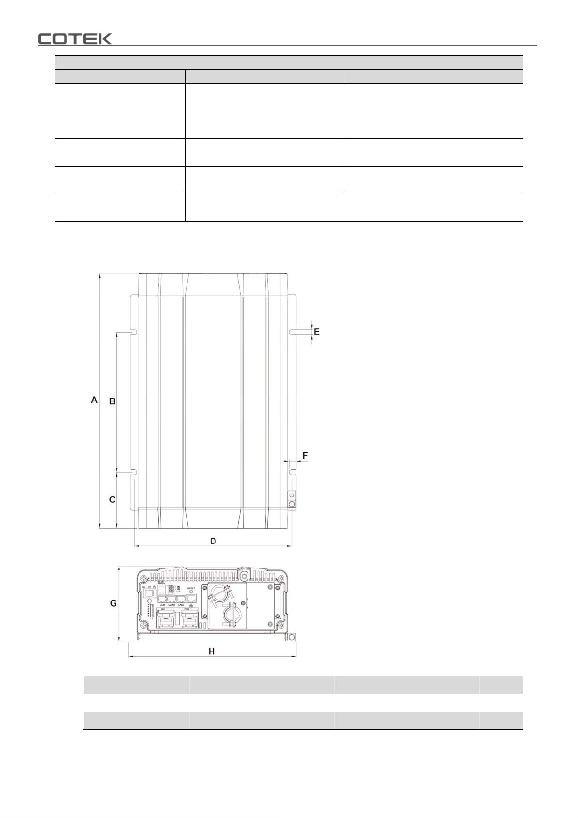
Transfer-Time Table
Mode / Transfer Switch ATS STS
Frequency is synchronized: < 4ms.;
Haphazard
Normal
Exacting
Online
Inverter to utility AC: 8~10ms.;
Utility AC to inverter: 16~50ms.
Inverter to utility AC: 8~10ms.;
Utility AC to inverter: 16~25ms.
Inverter to utility AC: 8~10ms.;
Utility AC to inverter: 16~50ms.
Inverter to utility AC: 8~10ms.;
Utility AC to inverter: 16~25ms.
Table 1. SD series transfer-time
Frequency is not synchronized:
Inverter to utility AC: < 4ms.;
Utility AC to inverter: 16~50ms.
< 4ms
Inverter to utility AC: < 4ms.;
Utility AC to inverter: 16~50ms.
< 4ms
2-4. Mechanical Drawings
Figure 3. SD series mechanical drawings
Model A (mm) B (mm) C (mm) D (mm) E (mm) F (mm) G (mm) H (mm)
SD2500
SD3500
8
436 240.0 95.6 268.6 8.5 11.5 128 283
496 240.0 125.6 268.6 8.5 11.5 128 283
Table 2. SD series dimension
Page 13
3.Introduction
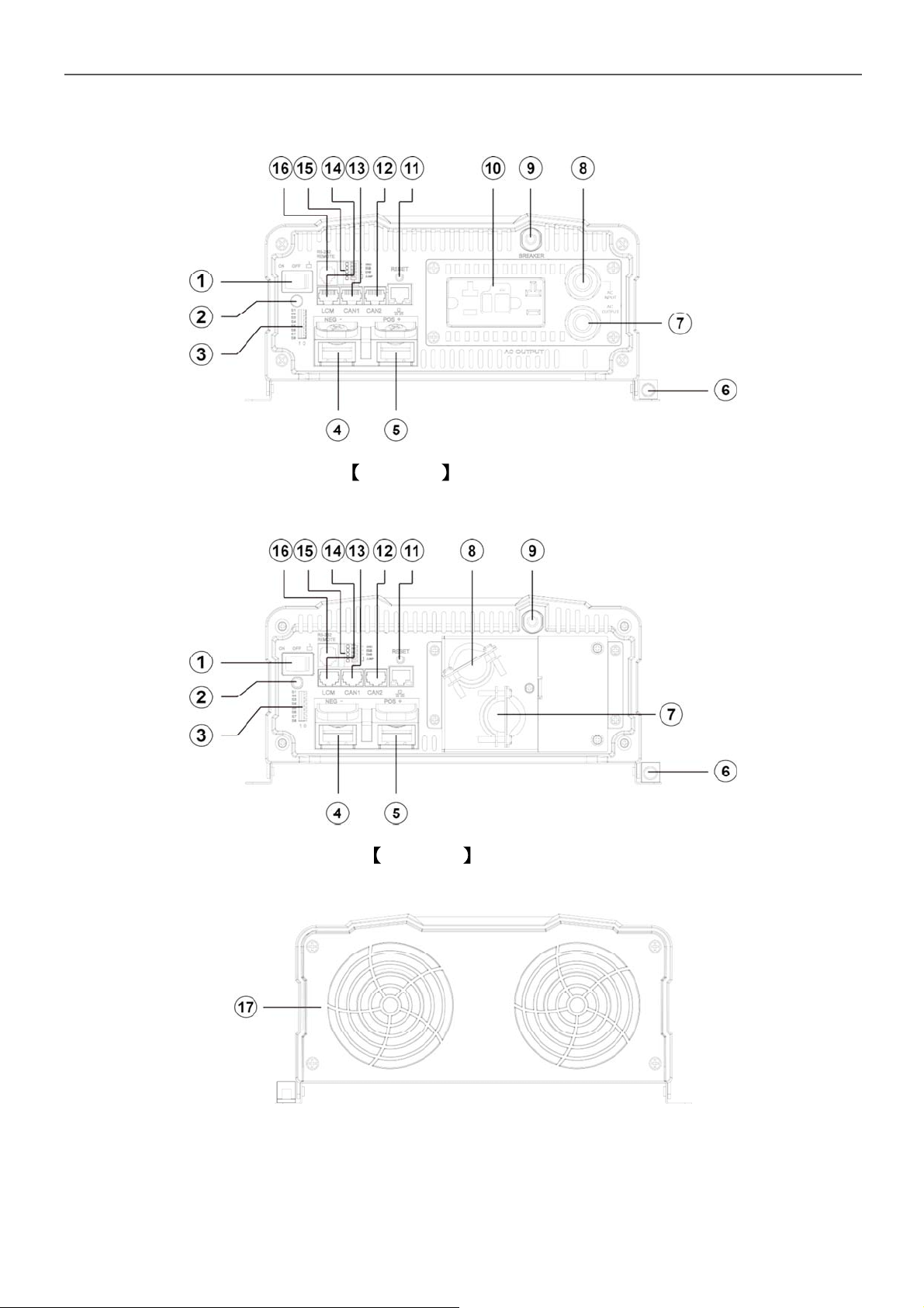
3. Introduction
Version 1 General Model
Figure 4. SD general model front panel
Version 2 UL Model
Figure 5. SD UL model front panel
Figure 6. SD series rear panel
9
Page 14
Front Panel / Rear Panel
1 Power ON/OFF/REMOTE (Main) switch 10 AC output socket
2 Status LED 11 Reset Button
3 Dip Switch (S1~S8) 12 CAN2 Port (only to be used in parallel mode)
4 DC Input - 13 CAN1 Port (only to be used in parallel mode)
5 DC Input + 14
6 Chassis Ground 15 Green terminal (Remote and Parallel select)
7 AC Output 16 Remote / RS-232 port
8 By-pass AC Input 17 FAN
9 AC input circuit breaker
Table 3. SD front panel / rear panel introduction
LCM Port (Connection for LCD remote control
panel)
3-1. Power ON / OFF / REMOTE (Main) switch
A. Before installing the inverter, please ensure the main switch is in the OFF position.
B. Before using the remote unit, please ensure the main switch is in the REMOTE
position.
C. Main switch ON / OFF will not control AC Grid input, therefore for any
maintenances please remove the AC Grid connection to prevent damage of SD
series, then turn off the Main switch to OFF position for maintenance service.
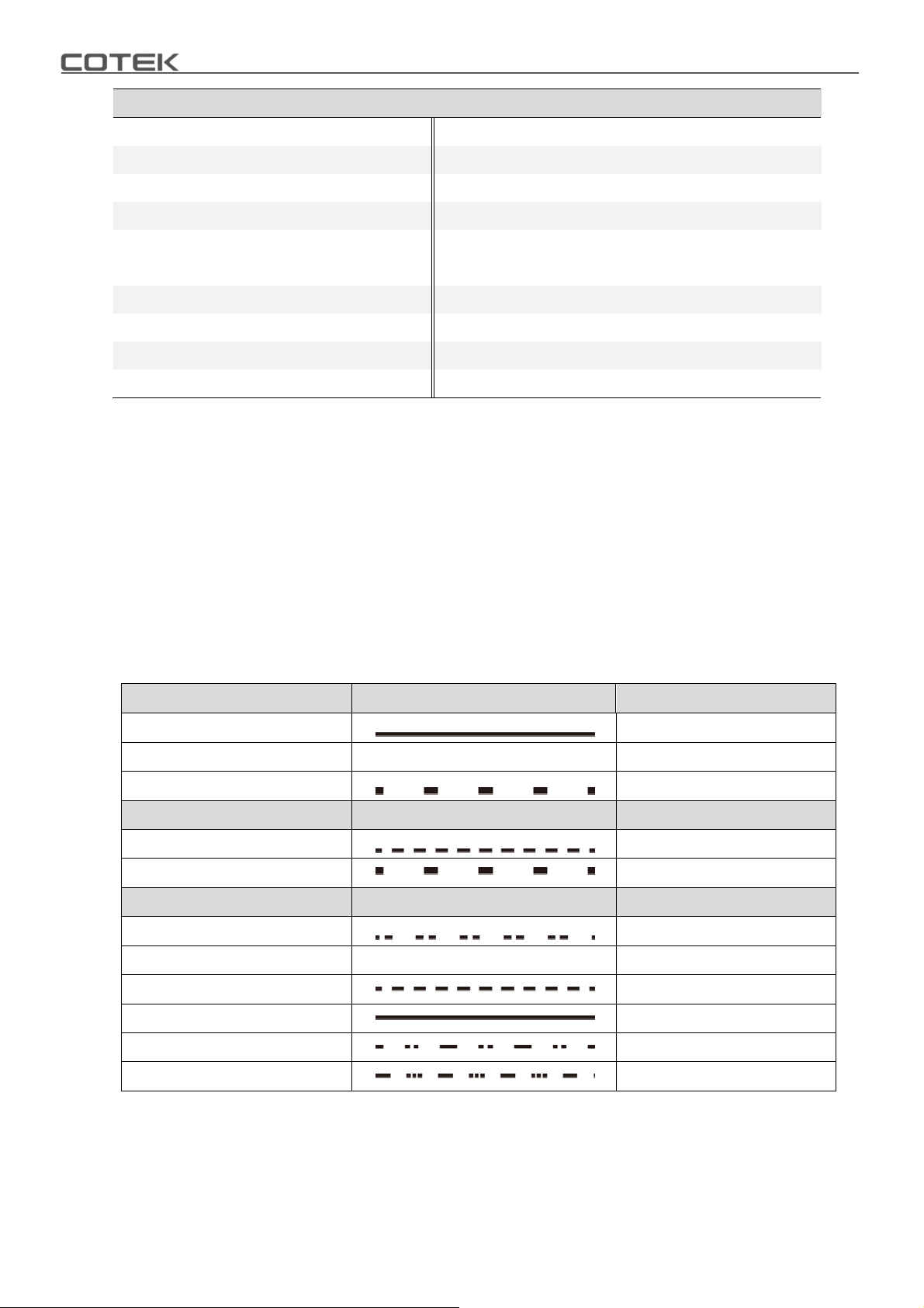
3-2. LED Indicator
Green LED
Solid
Slow Blink
Intermittent Blink
Orange LED LED Signal Status
Fast Blink
Slow Blink
Red LED LED Signal Status
Intermittent Blink OTP
Fast Blink
Slow Blink
Solid
Intermittent Blink
Intermittent Blink
LED Signal Status
Power OK
Power Saving
Bypass
OVP
UVP
OVP- Shut-down
UVP- Shut-down
OLP
Fan Failure
Component Failure
Table 4. SD LED indicator
10
Page 15
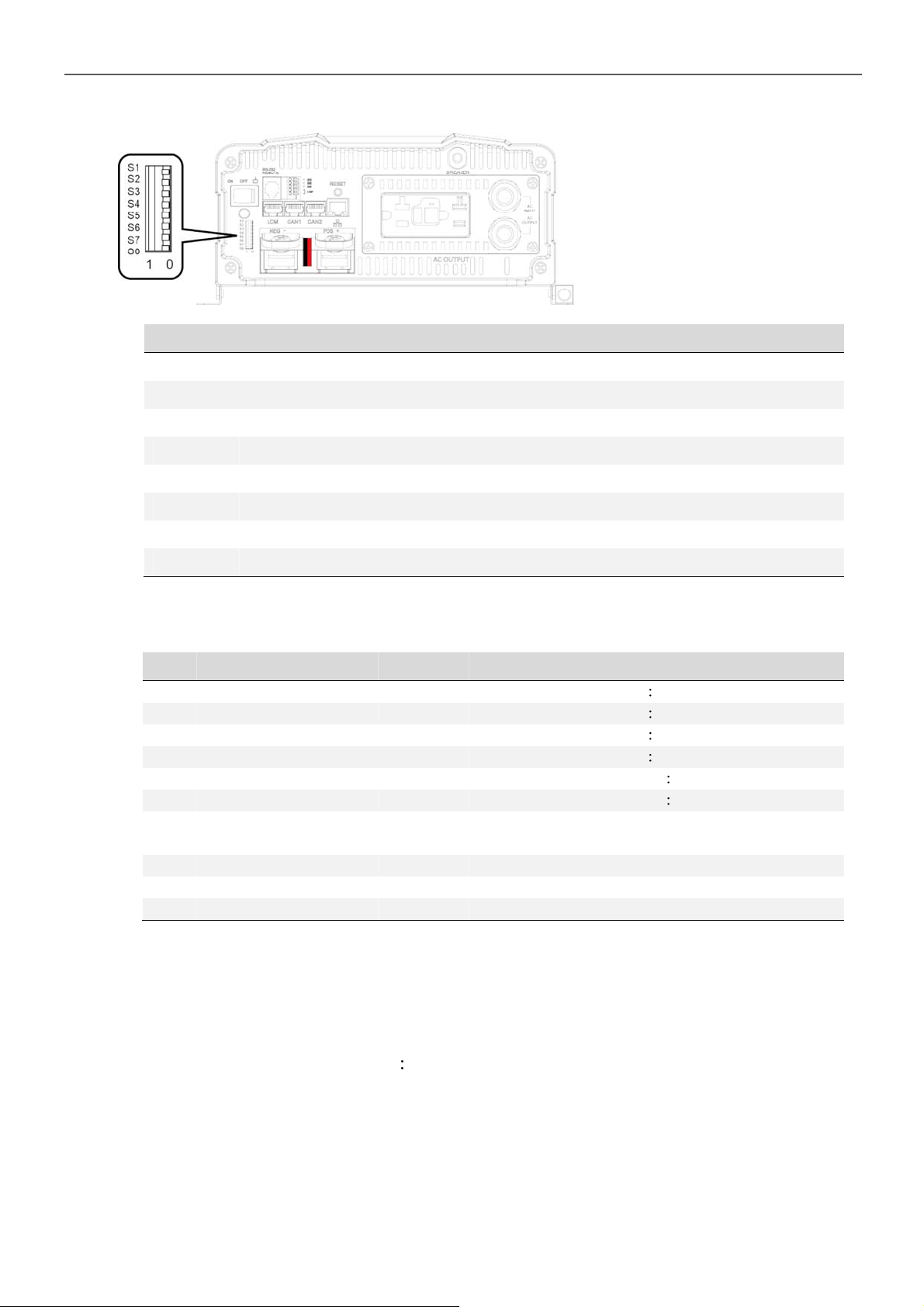
3-3. DIP Switch (S1~S8) Assignment
PIN# PIN Assignment
1 AC output voltage setting
2 AC output voltage setting
3 AC output frequency setting
4 To set-up 3 Phase output or Energy-saving level
5 To set-up 3 Phase output or Energy-saving level
6 To set-up 3 Phase output or Energy-saving level
3. Introduction
1=ON/0=OFF
Figure 7. DIP switch (S1~S8)
7 To set-up DIP Switch S4~S6 for power saving or 3 Phase output
8 To set-up function parameters adjustment via LCM port or DIP switch
Table 5. DIP switch (S1~S8) PIN assignment
3-3-1. DIP switch set-up
S1 S2 S3 S4 S5 S6 S7 S8 Scenario
00XXXXXXAC output voltage
1 0 X X X X X X AC output voltage 110VAC/220VAC
01XXXXXXAC output voltage
1 1 X X X X X X AC output voltage 120VAC/240VAC
XX0 XXXXXAC output frequency
X X 1 X X X X X AC output frequency 60Hz
XXXXXX0 X
X X X X X X 1 X 3 Phase output setting (S4~S6)
XXXXXXX0 Adjust function parameters via LCM port
X X X X X X X 1 Adjust function parameters via DIP switch
1=ON / 0=OFF
Table 6. DIP switch set-up
Power saving mode setting (S4~S6); No
master-slave in parallel
100VAC/200VAC
115VAC/230VAC
50Hz
3-3-2. Power Saving Mode
Power Saving Mode is adjustable and set by the Dip Switches,S4, S5 and S6 on the
front panel. Example SD2500 Saving set 2%, the load is below 50W 10 sec. will into
saving mode, more than 150W or more leave saving mode.
A. Power device enter the saving mode
The rate power x setting % = the threshold enter the power saving model
In case the load less than threshold value 5 seconds, the power device will enter
the saving mode.
11
Page 16
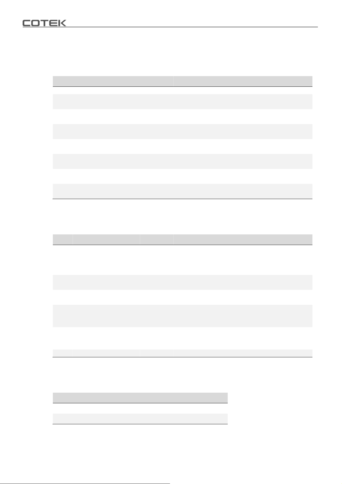
B. Power device leaving saving mode(re-start)
Restart threshold = rate power x setting % x 2~3
In case the power over the restart threshold, the power device will re-start and
provide the AC power.
S1 S2 S3 S4 S5 S6 S7 S8 Scenario
XXX0000X Power saving DISABLE
X X X 1 0 0 0 X
XXX0100X
X X X 1 1 0 0 X
XXX0010X
X X X 1 0 1 0 X
XXX0110X
X X X 1 1 1 0 X
1=ON / 0=OFF
Table 7. Power saving mode set-up
Go in power saving mode when output load is
under 2% of rating power
Go in power saving mode when output load is
under 3% of rating power
Go in power saving mode when output load is
under 4% of rating power
Go in power saving mode when output load is
under 5% of rating power
Go in power saving mode when output load is
under 6% of rating power
Go in power saving mode when output load is
under 7% of rating power
Go in power saving mode when output load is
under 8% of rating power
3-3-3. S4~S6 Set-up for parallel application
S1 S2 S3 S4 S5 S6 S7 S8 Scenario
Master (0°); "R" Phase
XXX0001X
X X X 0 0 1 1 X
XXX0111X
X X X 1 0 0 1 X
XXX1011X
X X X 1 1 1 1 X Disable parallel function
1=ON / 0=OFF
Table 8. Parallel application set-up
to be used for 1Ø3W output in series
connection(Master) or 3Ø4W output
connection("R" Phase)
Slave (0°) with current sharing
to be used in parallel connection only
Slave (180°), to be used for 1Ø3W output in
series connection(L-NN-L)
Slave (-120°), "S" Phase
to support "S" Phase be(-120°) in 3Ø4W
output connection
Slave (120°), "T" Phase
to support "T" Phase be(120°) in 3Ø4W
output connection
3-3-4. Parameter select: “S8” select SD’s parameter setting by dip switch or LCM port
Set Value S8
LCM port 0
DIP switch 1
1=ON / 0=OFF
Table 9. Parameter select
3-4. DC Input - (please refer to DC wiring connections on p.17)
12
Page 17
3. Introduction
3-5. DC Input + (please refer to DC wiring connections on p. 17)
3-6.Chassis Ground Connect the wire # 8 AWG to vehicle chassis
WARNING!
Operating the inverter without a proper ground connection may cause electrical
safety hazard.
3-7. AC Output (Please refer to hard wiring installation on p. 19)
3-8. By-pass AC input (please refer to hard wiring installation on p. 19)
3-9. AC input circuit breaker
The AC input circuit breaker protects the model from overload. When an overload
condition exists, the circuit breaker stops supplying output AC grid power. To reset it,
push the circuit breaker switch then the model will be back in normal operation. The
source fault should be corrected before you reset it.
3-10. AC output socket (please refer to 4-2-3. on p. 22)
3-11. Reset Button (only to be used for Ethernet interface)
The Reset Button is to be used to resume the IP address to factory default value
IP 192.168.100.181
Subnet Mask 255.255.255.0
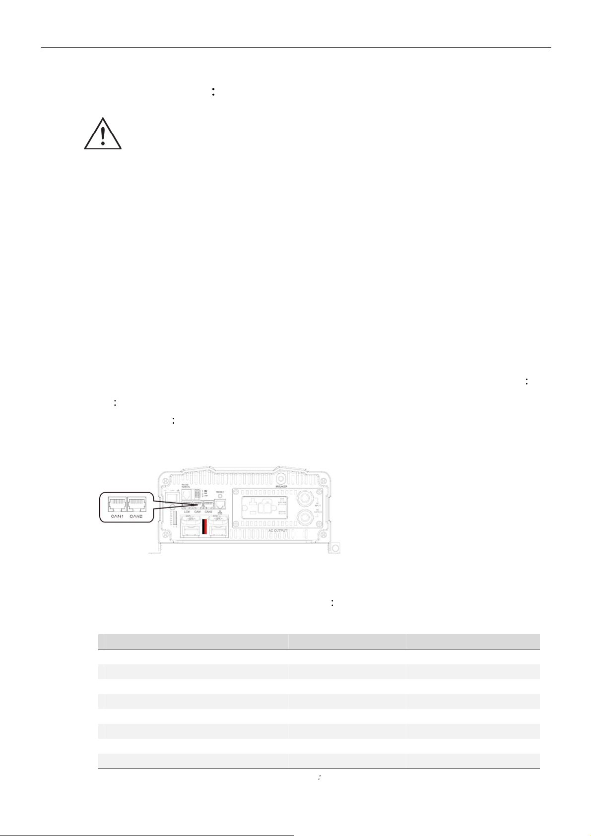
3-12. CAN1 and CAN2 Port (only to be used in parallel mode)
Figure 8. CAN1 and CAN2 port
1. Before using parallel mode, you need to ensure the green terminal’s parallel jump
status is set to ON.
2. Use the RJ-45 line (RJ-45 network cable parallel connection) to link one of the
SD Series CAN1 (CAN2) port to the other CAN1 (CAN2) port.
PIN# LCM port CAN1 port CAN2 port
1 CANH CAN_H CAN_H
2 CANL CAN_L CAN_L
3 P1 Reserved Reserved
4 VCC- Reserved Reserved
5 VCC+ Reserved Reserved
6 DIS Reserved Reserved
7 5VS- RND RND
8 5VS+ Reserved Reserved
Table 10. LCM, CAN1, CAN2 port PIN number and signal description
13
Page 18
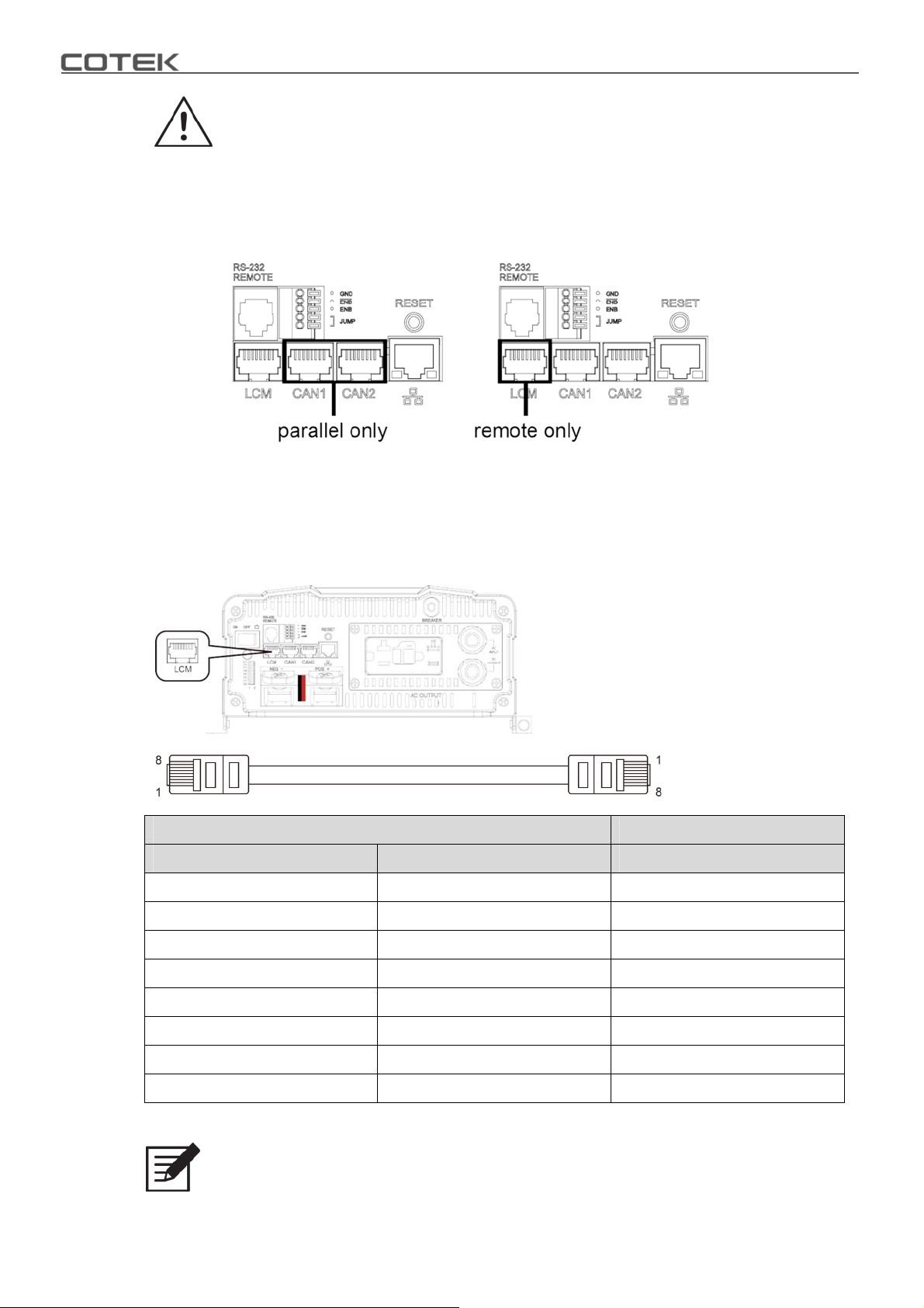
WARNING!
LCM port is for remote control connection only.
Please make sure the connection is correct. (CAN cable to CAN1 / CAN2
port , Remote cable to LCM port)
If CAN cable is connected to LCM port, or vice versa, the inverter will be
damaged.
3-13. LCM Port
Connection for LCD remote control panel, you can set and display the SD-series
operation status.
Figure 9. LCM port
Figure 10. LCM cable
LCD Remote Control Panel SD Series
PIN Num. Signal Description PIN Num.
1CANH1
2CANL2
3PON3
4 VCC- 4
5VCC+5
6DIS6
75VS-7
85VS+8
Table 11. PIN number and signal description for LCD remote control
Note
14
The cables should be as short as possible (less than 32.8 feet / 10 meters) so
that they can handle the signal.
Page 19
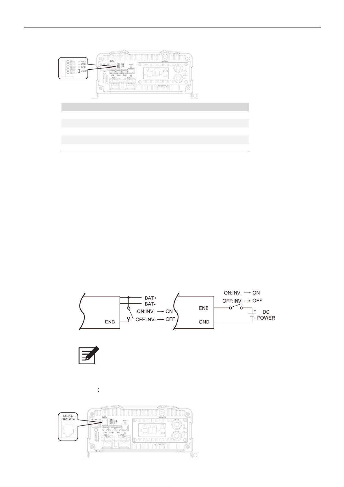
3-14. Green terminal (Remote and Parallel select)
Figure 11. Green terminal
PIN # PIN Assignment
1GND
2 -ENB
3ENB
4 Parallel Jump
5 Parallel Jump
Table 12. Green terminal PIN assignment
3-14-1. Parallel Jump Function (please refer to section 5 for further detailed info.)
1. Before installing the inverter, you need to ensure the main switch is in the
3. Introduction
OFF position.
2. Use 20 ~ 24 #AWG wire to connect the parallel jump terminal.
3-14-2. Remote Control Function
1. Before installing the inverter, please ensure that the main switch is in the
OFF position.
2. Before using the remote control terminal, please ensure the main switch is
in the REMOTE position.
3. Use 20 ~ 24 #AWG wire to connect the remote control terminal.
4. Remote control ON/OFF inverter setup status.
Figure 12. Remote control function setting
Note
The above 4 methods can be used to turn ON/OFF.
3-15. RS-232 Port
RS-232 Port Serial port monitoring and control through computer’s interface.
Figure 13. RS-232 port
15
Page 20
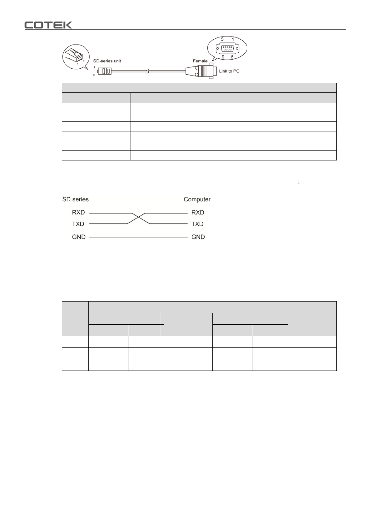
Figure 14. RS-232 cable
SD Series Computer
PIN Num. Signal Description PIN Num. Signal Description
1 Not used 1 Not used
2GND5GND
3 RXD 3 TXD
4 TXD 2 RXD
5 Not used Not used
6 Not used Not used
Table 13. The connection between SD series and computer
The connection between this SD-series and the computer is as follows
Figure 15.
The connection between SD series and computer
3-16. Fan Ventilation
The rear panel must keep the distance at least 1 inch from any surrounding items.
3-17. Protections Features
DC Input (VDC)
Model
12V 16 ± 0.25 15 ± 0.25 15.5 ± 0.25 10 ± 0.25 12.5 ± 0.25 10.5 ± 0.25
24V 32 ± 0.5 30 ± 0.5 31 ± 0.5 20 ± 0.5 25 ± 0.5 21 ± 0.5
48V 64±1 60± 1 62± 1 40± 1 50± 1 42± 1
À
OVA only LED prompt, no beeper alarm.
Over Voltage Over Voltage
À
Shut-down Restart Shut-down Restart
Table 14. Protections Features
Alarm
Under Voltage Under Voltage
Alarm
16
Page 21
4. DC Wiring Connections
4.DC Wiring Connections
Follow the instructions to connect the battery cables to the DC input terminals of the
Inverter. The cable should be as short as possible (less than 6 feet / 1.8 meters ideally)
so that it can handle the required current in accordance with the electrical codes or
application regulations. Inappropriate length of cables will reduce the inverter
performance such as poor surge capability, frequent low-input voltage warnings, and
shut-down. When under voltage protect condition, please check the cable size and
specification (length and diameter should conform to manual requirements) between
battery and SD model.
The longer or the narrower the cable is, the more the voltage drops. Increasing your DC
cable diameter will help to improve the situation will help improve the situation.
The following are recommended cable diameter for the best performance of the inverter.
(Applies to both 120V and 230V versions)
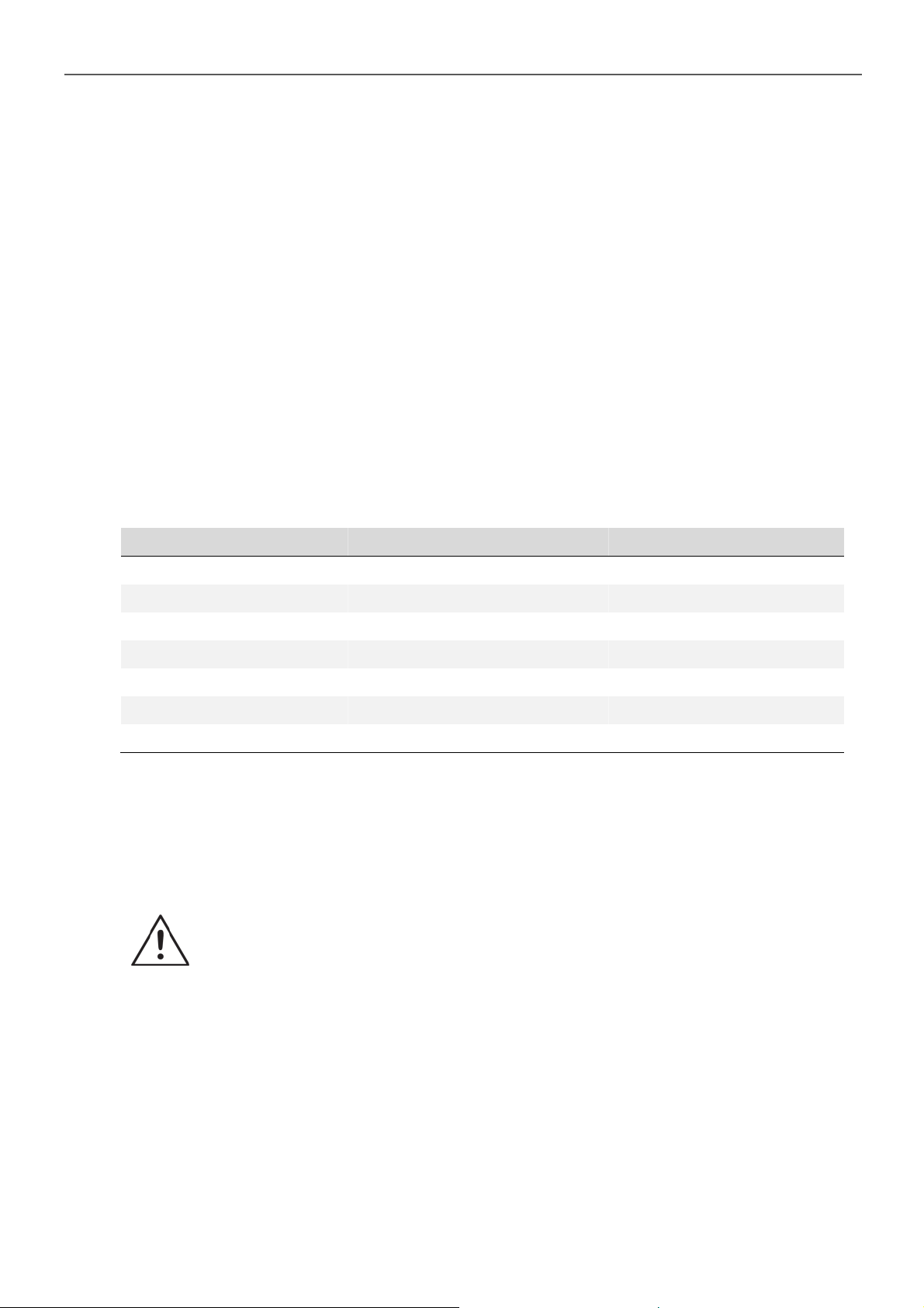
Model No. Wire AWG Inline Fuse
SD2500-112 / 212 # 3/0 350 A
SD2500-124 / 224 # 1 175 A
SD2500-148 / 248 # 4 90A
SD3500-112 / 212 # 4/0 500 A
SD3500-124 / 224 # 0 250 A
SD3500-148 / 248 # 2 125 A
SD2500-112 / 212 # 3/0 350 A
Table 15. SD series wiring cable diameter and inline fuse
Connect the cables to the power input terminals on the front panel of the inverter. The
red terminal is positive (+) and black terminal is negative (-).
Insert the cables into the terminals and tighten the screw to clamp the wires securely.
WARNING!
1. Make sure all the DC connections are tight (torque to 11 ft-lbs, 15 Nm Max.).
Loose connections could overheat and result in a potential hazard.
2. The installation of a fuse must be on the positive cable. Failure to place a
fuse on “+” cables running between the inverter and battery may cause
damage to the inverter and will void warranty.
Also, only use high quality copper wire and keep the cable length short - maximum of
3 - 6 feet.
17
Page 22
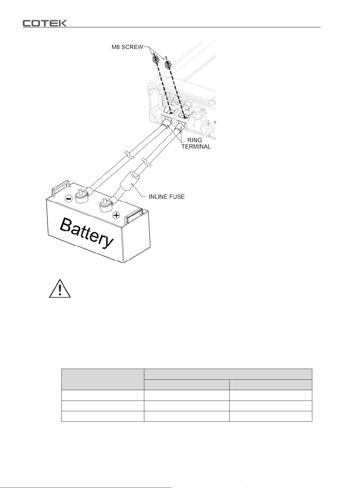
Do not place anything
between battery cable lug
and terminal surface.
Assemble exactly as shown.
Figure 16. Battery cabling
WARNING!
During the first installation, it is normal to experience a small spark is a normal
phenomenon because the internal capacitors charging. Do not be concerned.
4-1. DC Input Terminals
Connect DC input terminals to 12V / 24V / 48V battery or other power sources.
[ + ] represents positive, [ - ] represents negative. Reverse polarity connection can
blow the internal fuse and may damage the inverter permanently.
18
Model
DC Input Voltage
Minimum Maximum
12V 10V 16V
24V 20V 32V
48V 40V 64V
Table 16. SD series DC input voltage range
Page 23
4. DC Wiring Connections
4-2. Hard-wire Installation
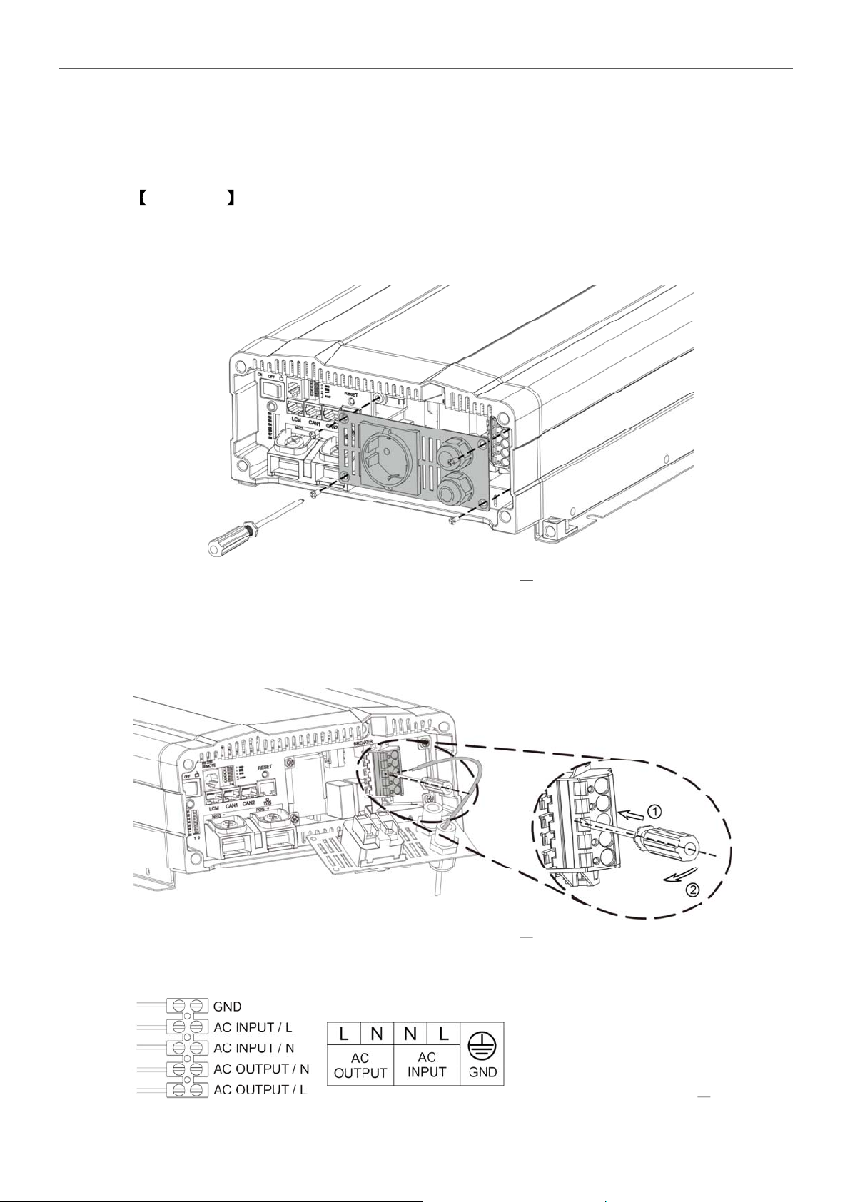
4-2-1. SD series provides the flexibility of hard-wire connection, and this function will
make external control panel wiring easier.
Version 1 General model
Step 1.
Remove the four screws of AC wiring compartment and pull it out with care.
Figure 17. General model setting Step 1
Step 2.
Pull the line through the snap bushing of the AC wiring compartment cover then
follow below picture operation.
Figure 18. General model setting Step 2
100VAC~120VAC / 200VAC~240VAC System
Figure 19. General model setting AC wiring
19
Page 24
Note
The only difference between 110V and 220V is within the AC Input breaker
L or N and thus will not affect the wiring configuration.
Note
In case that user wants to install the earth-leakage circuit breaker, COTEK
recommend time delay type. The major specification of the circuit breaker
is as following
Earth-leakage current 100mA, 300mA, 500mA
Time 0.45 second, 1 second, 2 seconds
Recommend model NV50-SN, Time delay type of Shihin Electric
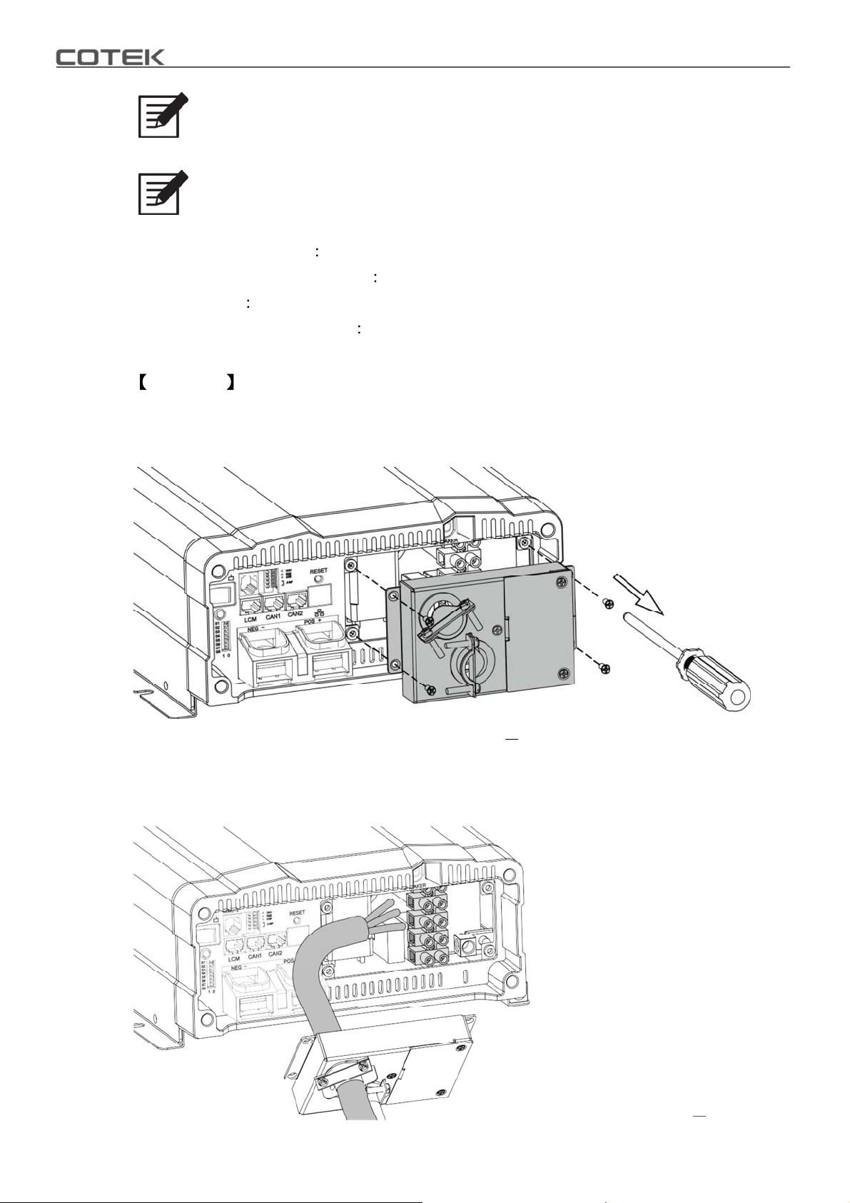
Version 2 UL model
Step 1.
Use the screwdriver to remove the cover.
Figure 20. UL model setting Step 1
Step 2.
AC cable pass through the ring. Wire the AC cable on the terminal.
Figure 21. UL model setting Step 2
20
Page 25
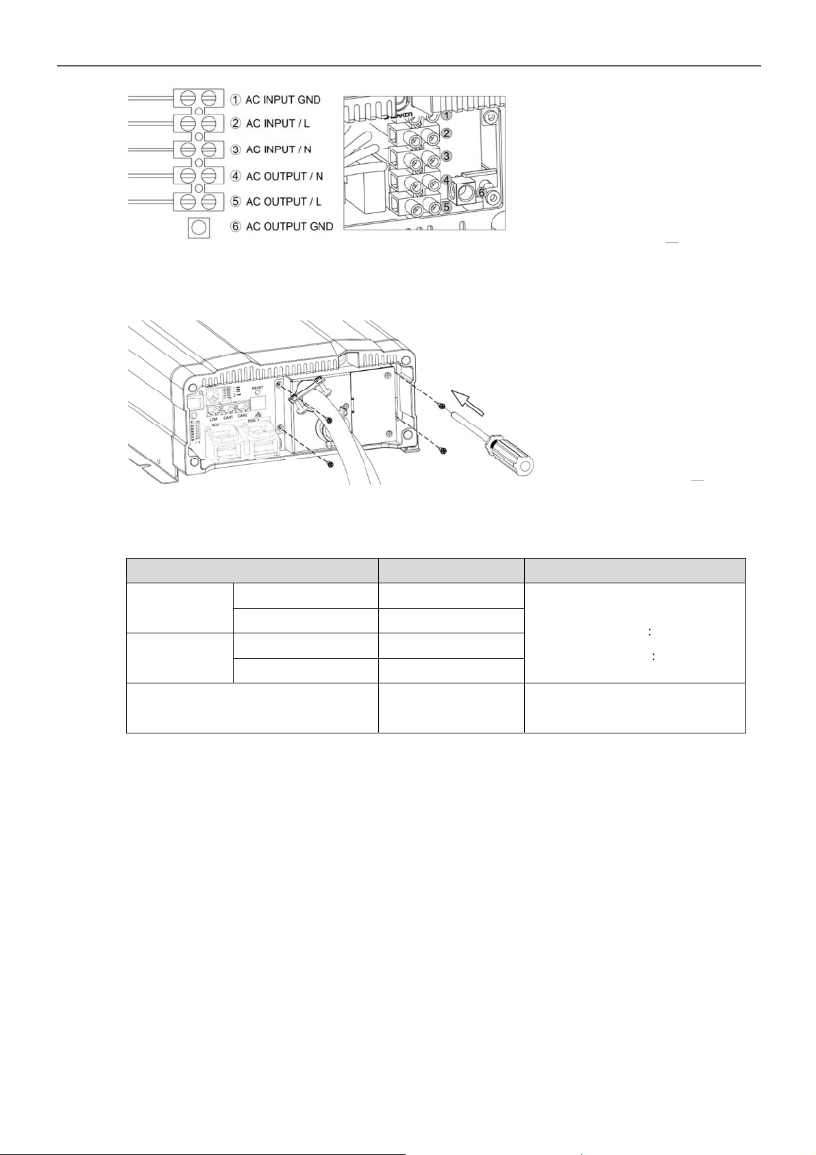
Step 3.
Use the screwdriver to fix the cover.
4. DC Wiring Connections
Figure 22. UL model setting AC wiring
Figure 23. UL model setting Step 3
4-2-2. Connect AC output and AC input wiring to the SD series terminals.
Please take the following information as your reference.
Terminal Wire Color Wire Length / Gauge
AC OUTPUT
AC INPUT
Ground
Line (L) Black
Neutral (N) White
Line (L) Brown
Neutral (N) Blue
Green / Yellow or
Bare copper
Table 17. Wire Color / Wire Length / Wire Gauge
Within 16 feet / AWG#
200-240VAC
100-120VAC
26~32 feet / AWG#10~12
12AWG
8AWG
CAUTION!
It is advised that all the electrical installation should conform to the local electrical
codes and should be carried out by a certified technician.
When the unit is feeding the internally inverted voltage, the current carrying
conductors connected to the “L” and “N” terminals of the AC output will be isolated
from the metal chassis of the inverter. Hence, during this condition, when the metal
chassis of the inverter is connected to the earth ground, the “N” terminal of the AC
output will not be grounded (bonded) to the earth ground. Under this condition, the
“N” terminal of the AC output will not be a Neutral in the true sense. Do not touch this
terminal as it will be at an elevated voltage (almost half the value the AC output
voltage) with respect to the metal chassis / earth ground and may produce an
electrical shock when touched!
21
Page 26
When the unit is transferring power from the AC input source, the grounding
condition of the “N” terminal of the AC output will be the same as the condition of the
“N” terminal of the AC input source. If the AC input source is the power supplied from
the utility, the “N” terminal would be a Neutral in the true sense. It will normally be
bonded to the earth ground and will read almost 0 V with respect to the earth ground.
In this case, touching this terminal will not be a shock hazard.
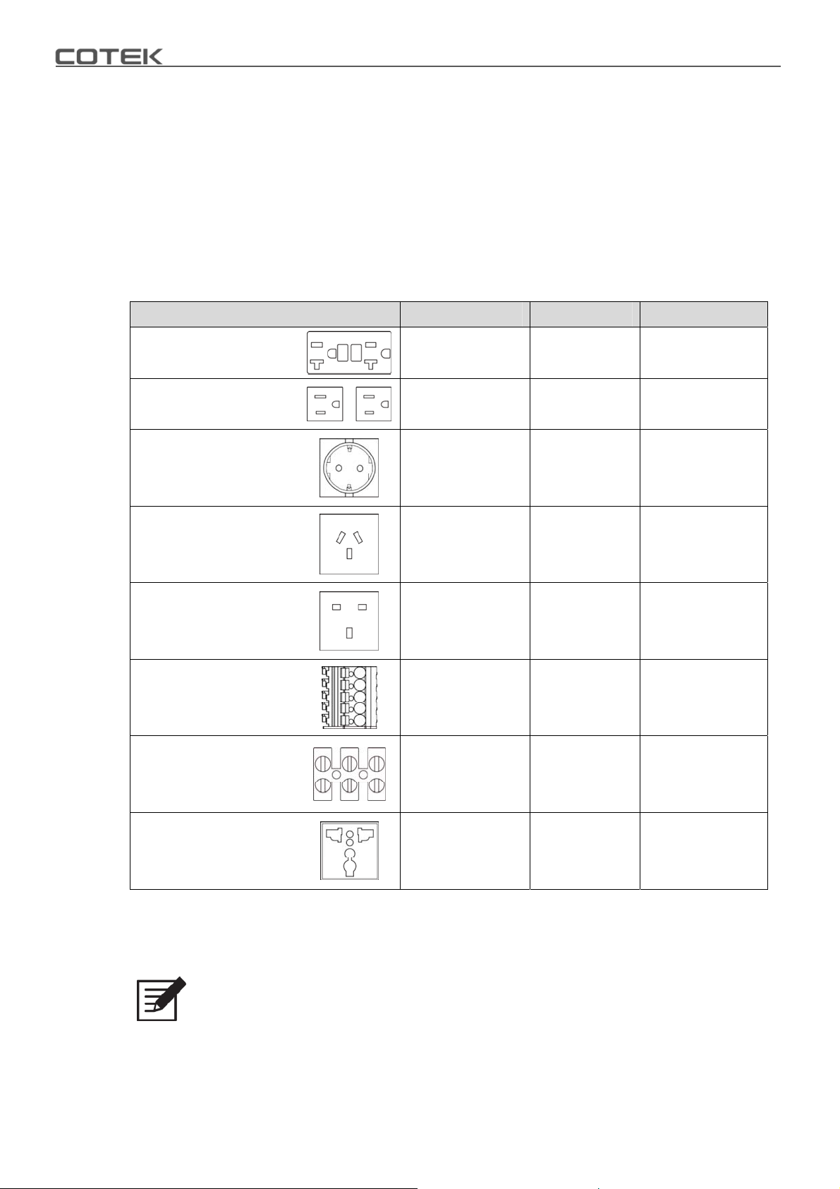
4-2-3. AC output and terminals of the SD series, you can use both the front wiring
terminal and outlet, as they are connected in parallel.
Type Number of outlet Voltage (VAC) Total Current (A)
GFCI 2 125 20
NEMA 2 125 15
Europe 1 250 16
Australia / New Zealand 1 250 15
U.K. 1 250 13
Wiring Terminal 1 100~250 35
①
UL458
②
Universal
① UL458 only support 112 and 124 model.
② Only CE (200-240V Type) and FCC (100-120V Type) standard approve.
Table 18. AC input socket / Wiring terminal
1 120 35
1 100~250 16
22
Note
In case the load current over the outlet rated current, please use the hared
wire terminal next to the outlets.
Page 27
4. DC Wiring Connections
Note
Recommend GFCI connector
y HUBBELL INC WIRING DEVICE DIV, Type GF20 and GFRST20. Rated
125V, 20A
y COOPER WIRING DEVICES, Type VGF20 and SGF20. Rated 125V,
20A
y LEVITON MFG CO INC, Type 7899-W and GFNT2. Rated 125V, 20A
y PASS & SEYMOUR INC, Type 2097. Rated 125V, 20A
WARNING!
When using full power, it is recommended to use the wiring terminal.
23
Page 28
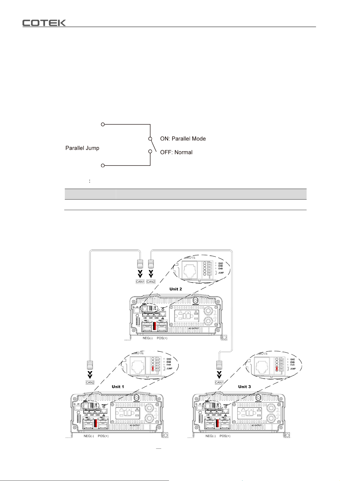
5.Parallel Mode
5-1. Prepare for Parallel Usage
1. Before setting, you need to ensure that the main switch is ”OFF”.
2. Before using the parallel function, you need to set the parallel jump of the green
terminal the status of which must be “ON”, if the between in another SD is set
to ”OFF” which is termination resistors.
Example If three SD inverters are paralleled, setup green terminal.
Parallel Unit 1 Unit 2 Unit 3
Parallel Jump ON OFF
Figure 24. Parallel jump setting
À
ON
ÀIf you parallel N units, the first (unit 1) and the last unit (unit N) must set parallel jumper in ON
position.
Table 19. Jumper setting for parallel usage
24
Figure 25. Sample
three SD inverters are paralleled
Page 29
5. Parallel Mode
Note
The simple method to determine the terminal resistor No need to set the
terminal resistor when CAN1 and CAN2 port have wiring.
Note
SD series can be used for N+1 (N 14) redundancy and the ability of
enlarge the capacity (Users can install maximum 15 units of inverters
together in parallel in order to provide the power expansion).
3. Before using the parallel function, you need to set voltage and frequency of all
units’ DIP switches to the same selection (refer to section 3-3).
4. Check RJ-45 line connects already.
5. SD series based on master-slave architecture and support auto master function.
User only set one SD parameters and other SDs will follow the master SD
setting.
5-2. Industry Applications
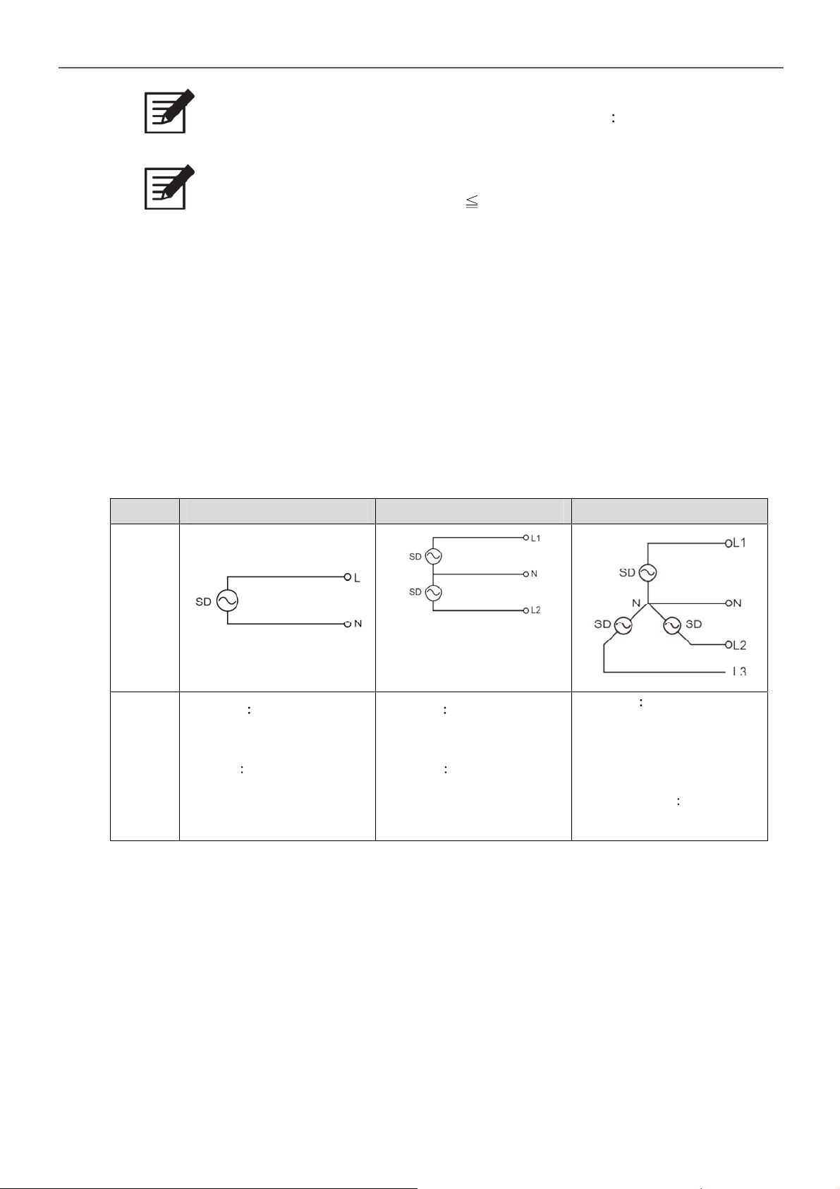
Type 1Φ2W 1Φ3W 3Φ4W
Drawing
The SD series create 1Ф3W
power system, L1-L2 Voltage
is L1-N double.
Example
SD2500-124 set output 100V /
50Hz
The phase voltage is 100V /
50Hz (L1-N, L2-N, L3-N)
The line voltage
L2-L3 ~ 173V/50Hz
Example
Example
SD2500-124 set output 100V /
50Hz
The L-N
100V / 50Hz
Example
SD2500-124 set output 100V /
50Hz
The L1-N
100V / 50Hz
L1-L2, L1-L3,
25
Page 30
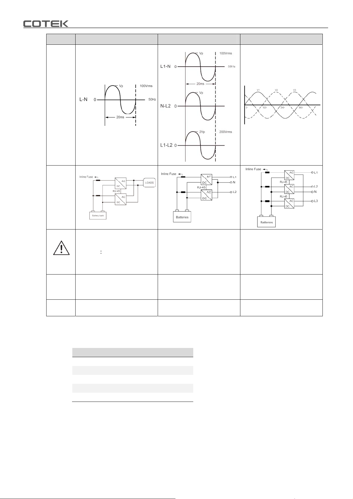
Type 1Φ2W 1Φ3W 3Φ4W
Waveform
Battery
Set up
Transfer Switch STS
Warning
module
& 1P3W & 3P4W < 6ms
Single < 4ms; N+1
DIP
Switch
Refer to 5-2-1. / 5-2-2. Refer to 5-2-3. Refer to 5-2-4.
Setting
Wiring
Diagram
Refer to Figure 30. / Figure 31. Refer to Figure 32. Refer to Figure 33.
5-2-1. 1Φ2W Switch Table
Master Slave 0°
S4 0 0
S5 0 0
S6 0 1
S7 1 1
S8 1 1
Table 21. 1Φ2W switch table
Do not support N+1
operation, maximum of two
SD inverters, THD < 4%
Table 20. Parallel industry applications
Do not support N+1
operation, maximum of three
SD inverters, THD < 4%
ÀDIP switch (S7) must be set to
“1” À
26
Page 31
5-2-2. 1Φ2W Switch Table Auto Master
Auto Master
S4 0
S5 0
S6 0
S7 0
S8 1
Table 22. 1Φ2W switch table auto master
5-2-3. 1Φ3W Switch Table
Master Slave 180°
S4 0 0
S5 0 1
S6 0 1
S7 1 1
S8 1 1
Table 23. 1Φ3W switch table
5. Parallel Mode
5-2-4. 3Φ4W Switch Table
L1 Master L2 -120° Slave L2 +120° Slave
S4 0 1 1
S5 0 0 0
S6 0 0 1
S7 1 1 1
S8 1 1 1
Table 24. 3Φ4W switch table
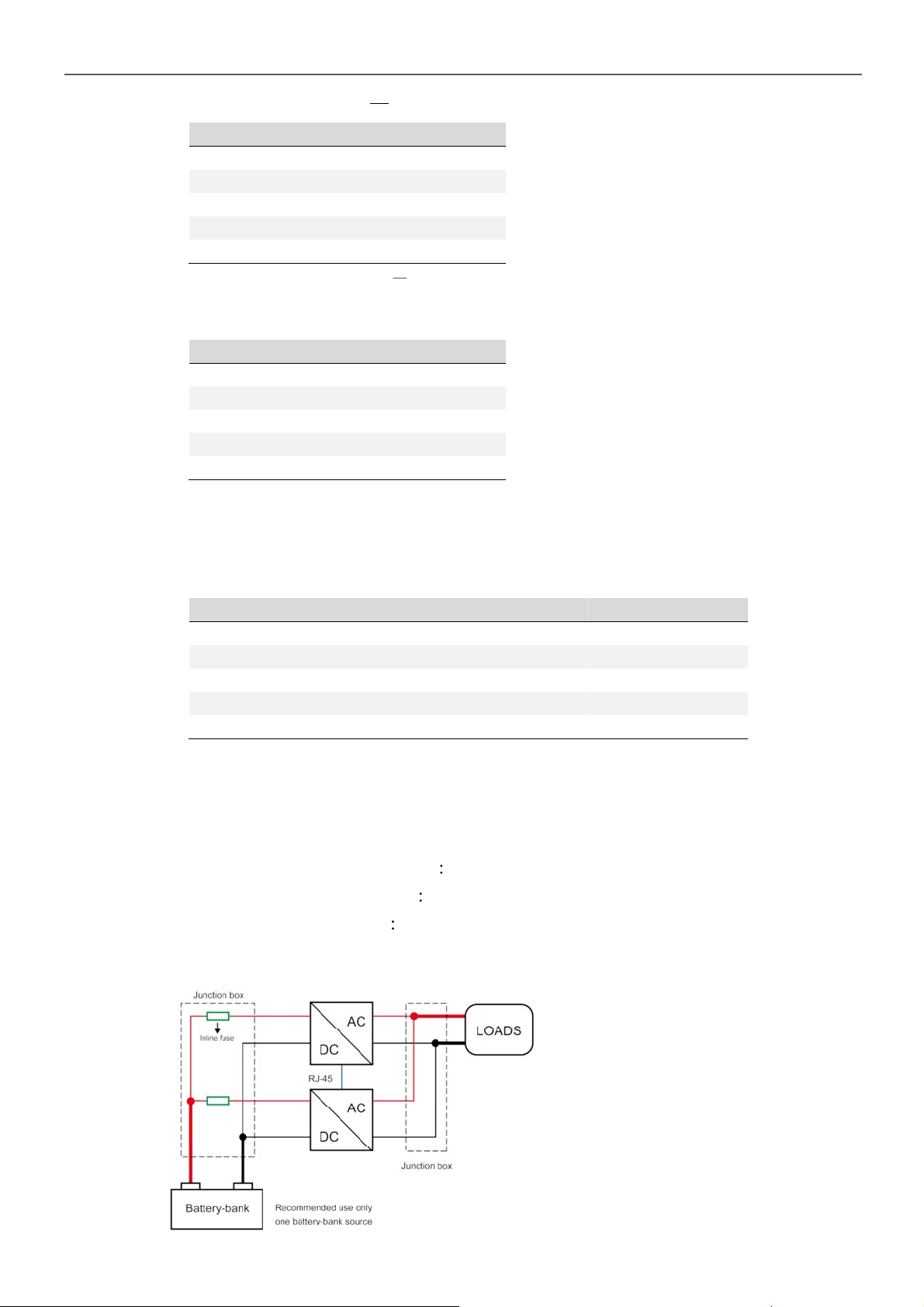
5-3. Wiring for Parallel Usage
5-3-1. Connection method
1. AC OUTPUT connector setup Line link to Line; Neutral link to Neutral.
2. AC INPUT connector setup Line link to Line; Neutral link to Neutral.
3. Battery connector setup POS+ link to POS+; NEG - link to NEG –
5-3-2. Connection Diagram
Figure 26. Connection Diagram_1
27
Page 32
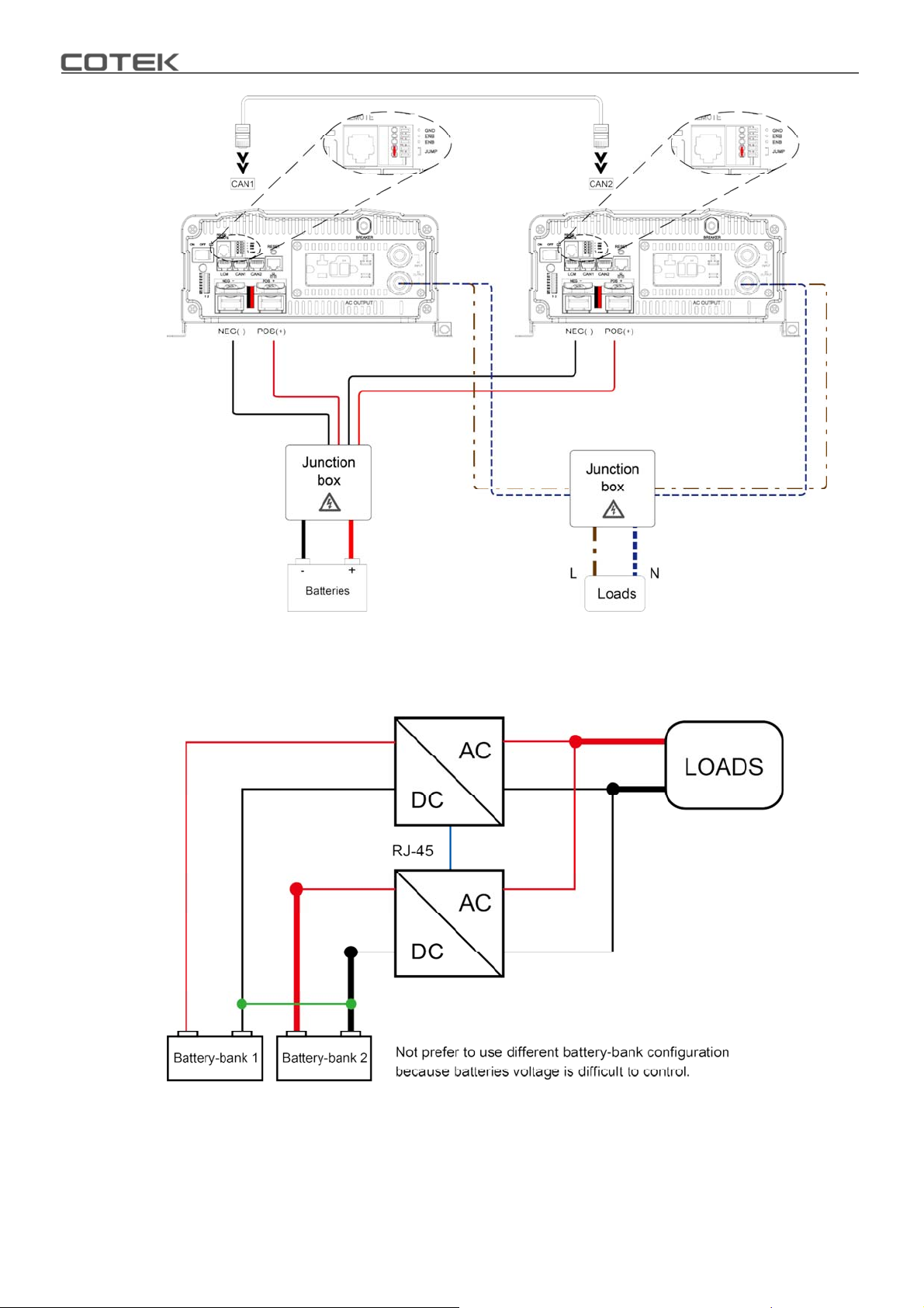
Figure 27. Connection Diagram_2
28
Figure 28. Connection Diagram_3
Page 33
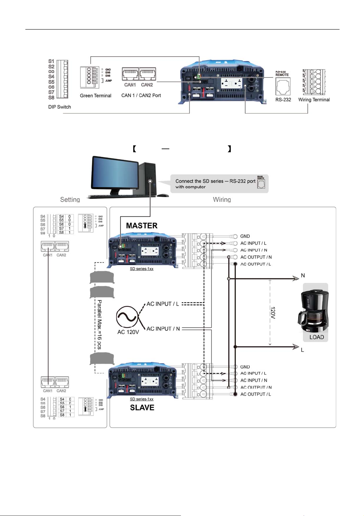
5-4. AC Wiring Diagram
Figure 29. SD series front panel introduction
1Φ2W Wiring Diagram
5. Parallel Mode
Figure 30. 1Φ2W parallel AC wiring diagram
29
Page 34
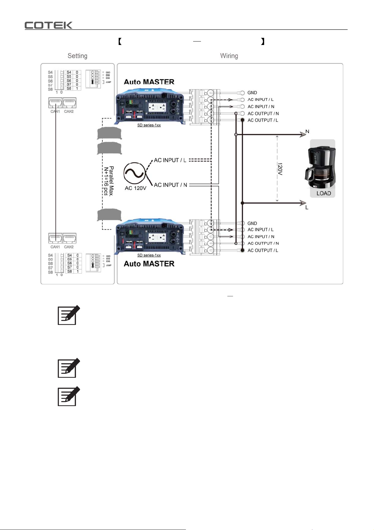
1Φ2W Auto Master Wiring Diagram
Figure 31. 1Φ2W parallel AC wiring diagram auto master
Note
Auto master can be operated under 1Φ2W mode.
Under 1Φ2W auto master mode, please set up the inverter by Ethernet or
Remote control CR-10.
Note
1Φ2W system parallel Max. N+1=16
Note
If you parallel N units, the first (unit 1) and the last unit (unit N) must set
parallel jumper in ON position.
30
Page 35
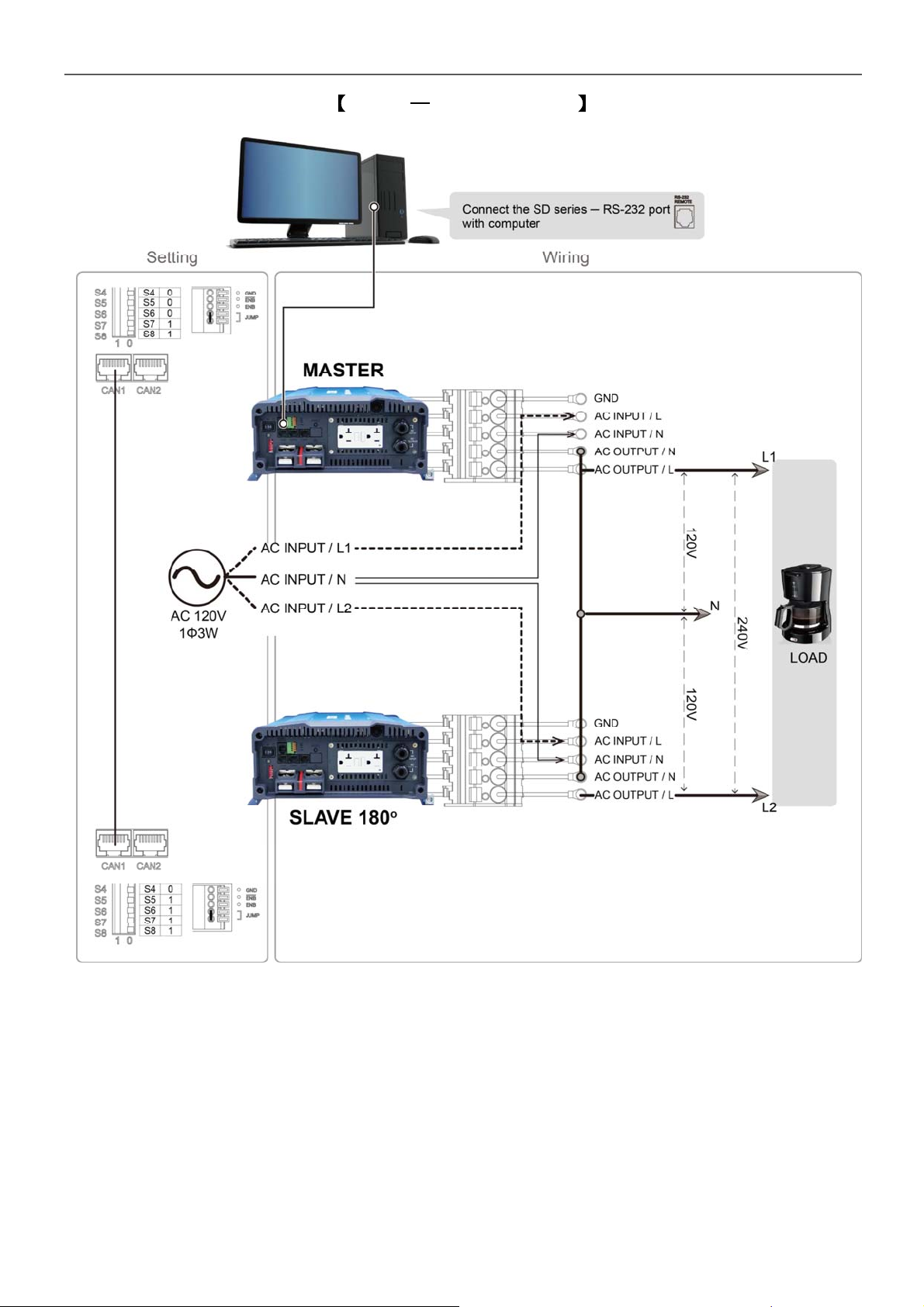
1Φ3W Wiring Diagram
5. Parallel Mode
Figure 32. 1Φ3W parallel AC wiring diagram
31
Page 36
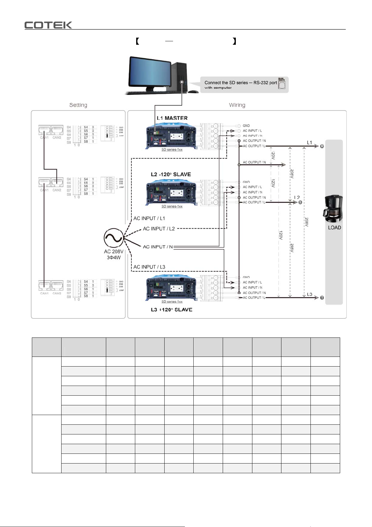
3Φ4W Wiring Diagram
Model
SD2500
SD3500
32
Figure 33. 3Φ4W parallel AC wiring diagram
Connection /
Output VAC
L1-to-L2 173 191 199 208 346 381 398 416
L2-to-L3 173 191 199 208 346 381 398 416
L3-to-L1 173 191 199 208 346 381 398 416
L1-to-N 100 110 115 120 200 220 230 240
L2-to-N 100 110 115 120 200 220 230 240
L3-to-N 100 110 115 120 200 220 230 240
L1-to-L2 173 191 199 208 346 381 398 416
L2-to-L3 173 191 199 208 346 381 398 416
L3-to-L1 173 191 199 208 346 381 398 416
L1-to-N 100 110 115 120 200 220 230 240
L2-to-N 100 110 115 120 200 220 230 240
L3-to-N 100 110 115 120 200 220 230 240
100V 110V 115V 120V 200V 220V 230V 240V
Table 25. Connection & output VAC under 3Φ4W
Page 37
5. Parallel Mode
5-5. Remote command for the parallel connection
There are two ways for parallel connection remote setting 1. RS-232, 2. CAN-Bus.
The RS-232 communication protocol not support broadcast function. In case of
the remote control use the RS-232 port, please follow the setting steps for the SD
setting.
RS-232 remote communication setting
1. Select one SD to be the Master and follow the setting
Scenario S1 S2 S3 S4 S5 S6 S7 S8
MasterXXX0 001X
Table 26. RS-232 remote communication setting
2. Please make sure the RS-232 communication cable connect to Master unit.
WARNING!
There is only one master in the system.
5-6. Remove Parallel Connection
1. Turn off the power.
2. Remove the RJ-45 cable (parallel connection signal cable).
3. Remove the AC parallel connection cable.
4. Remove the DC parallel connection cable.
33
Page 38
6.RS-232 Command
6-1. RS-232 command introduction
6-1-1. RS-232 command
Command format
This unit uses high-level language commands with a CR (0DH) and LF (0AH) as
the end of the command.
The system would interpret and execute the command only after these two
characters are received. After the unit execute the command, it would send a
response string to the computer. The response string is as follows
= > CR LF Command executed successfully ? > CR LF Command error, not
accepted ! > CR LF Command correct but execution error (e.g. parameters out
of range).
If the command needs any information from the unit, the unit would send the
information back to the computer (with CR and LF) and then send the response
string to the computer.
6-1-2. RS-232 Command format
This unit supports the following command format.
There should always be a CR (0DH) and a LF (0AH) appended to the command
while sending the command to this unit.
Command Function Command Function
POWER 1
POWER 0
*RST
FRQ?
PINV?
Power on
Power off
Recovery default setting
Show frequency of SD
Show power of SD
Table 27. RS-232 command table
VINV?
IINV?
VGRID?
VBAT?
Show voltage of SD
Show current of SD
Show voltage of grid
Show voltage of battery
Note A space (ASCII code 20H) is needed between Power and <value>
Example Command to query the Functions No Format FUNC?
After “Enter”, the unit’s “Function Code” appears on the PC screen
34
Page 39
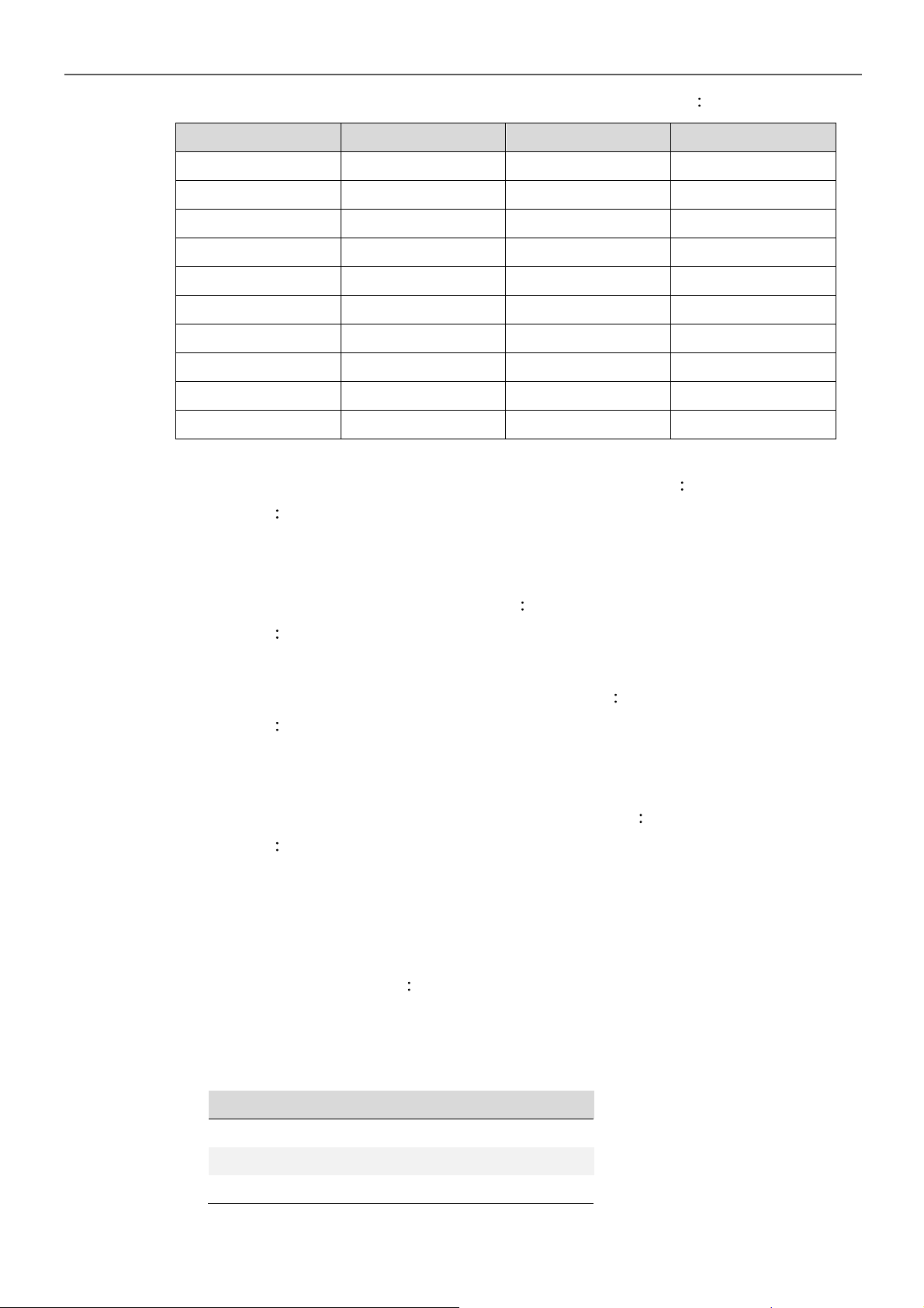
6-1-3. Command for accessing Setup Menus and adjusting values
<Function Code> Setting Menu <Function Code> Setting Menu
6. RS-232 Command
FUNC0
FUNC1
FUNC2
FUNC3
FUNC4
FUNC5
FUNC6
FUNC7
FUNC8
FUNC9
Table 28. Command for accessing setup menus and adjusting values
OVP Setting
OVP Recovery
UVP Setting
UVP Recovery
UV Alarm
O/P Voltage
RS-232 Baud rate
O/P Frequency
Sync Frequency
Overload Alarm
FUNC10
FUNC11
FUNC12
FUNC13
FUNC14
FUNC15
FUNC16
FUNC17
FUNC18
1. Select the Setup Menus with the help of Function Codes
Format FUNC <Function Code>
After “Enter”, the Setup Menu for the Function Code will be called.
The <Function Code>= 0~18
2. Command to query the Functions No
Shut-down retry
Saving Level
Saving Interval
Bypass Relay
LCD Contrast
LCD Auto-off
Buzzer Setting
Alert Setting
Language
Format FUNC?
After “Enter”, the unit’s “Function Code” appears on the PC screen.
3. Command to query the set value of the Function
Format SETT?
After “Enter”, the existing set value of the function appears on the PC
screen.
4. Command to set or adjust the value of the Function
Format SETT <value>
After “Enter”, the new value of the Function is set Choose the <value> of the
function.
6-1-4. Setting interface
1. OVP Setting <FUNC0> Set the Over Voltage Protection (OVP) and
shutdown.
Default = 16 VDC @ 12V Model, 32 VDC @ 24V Model, 64 VDC @ 48V
Model
Model Setting value range
12 V 15 VDC ~ 16 VDC
24 V 30 VDC ~ 32 VDC
48 V 60 VDC ~ 64 VDC
Table 29. OVP Setting <FUNC0>
35
Page 40
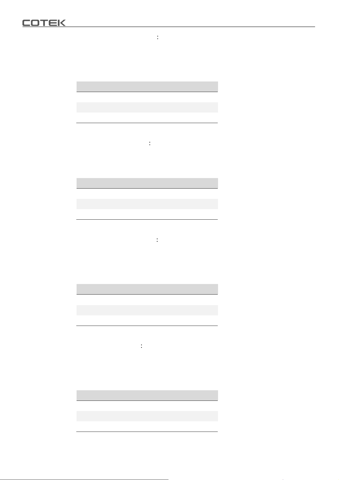
2. OVP Recovery <FUNC1> When the DC input voltage is higher than the
OVP setting, the SD-series shuts-down; once the input voltage falls below
the set OVP value, the SD-series will automatically restart.
Default = 15 VDC @ 12V Model, 30 VDC @ 24V Model, 60 VDC @ 48V
Model
Model Setting value range
12 V 13 VDC ~ 15 VDC
24 V 26 VDC ~ 30 VDC
48 V 52 VDC ~ 60 VDC
Table 30. OVP Recovery <FUNC1>
3. UVP Setting <FUNC2> Setting Under Voltage
Protection (UVP) and Shut-down on the inverter operation.
Default = 10 VDC@ 12V Model, 20 VDC @ 24V Model, 40VDC @ 48V
Model
Model Setting value range
12 V 10 VDC ~ 11 VDC
24 V 20 VDC ~ 22 VDC
48 V 40VDC ~ 44 VDC
Table 31. UVP Setting <FUNC2>
4. UVP Recovery <FUNC3> When the DC input voltage is below the set UVP
value, the SD-series shuts-down; Once the input voltage rises above the set
UVP value, the SD-series will automatically restart.
Default = 12.5VDC @ 12V Model, 25 VDC @ 24V Model, 50VDC @ 48V
Model
Model Setting value range
12 V 11.5 VDC ~ 13.5 VDC
24 V 23 VDC ~ 27 VDC
48 V 46 VDC ~ 54 VDC
Table 32. UVP Recovery <FUNC3>
5. UV Alarm <FUNC4> Setting Under Voltage (UV) alarm. When the input
voltage is lower than the set value, the SD-series will sound a “beep” to
remind you that the unit is going to shut-down.
Default = 10.5 VDC @ 12 V Model, 21 VDC @ 24 V Model, 42 VDC @ 48 V
Model
36
Model Setting value range
12 V 10.5 VDC ~ 11.5 VDC
24 V 21 VDC ~ 23 VDC
48 V 42 VDC ~ 46 VDC
Table 33. UV Alarm <FUNC4>
Page 41
6. RS-232 Command
Note
The value of the voltage set for the “UV Alarm” should be equal to or
higher than the value set for “UVP” or else the unit will shut-down
without any audible warning.
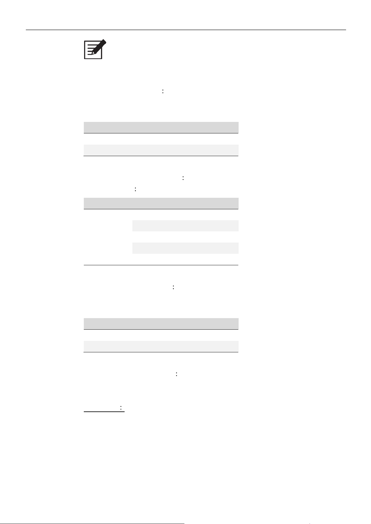
6. O/P Voltage <FUNC5> Setting the SD-series output voltage on the inverter
operation.
Default = 110 VAC @ 110 V Model, 230 VAC @ 230 V Model
Model Setting value range
110 V 97 VAC ~ 123 VAC
230 V 194 VAC ~ 246 VAC
Table 34. O/P Voltage <FUNC5>
7. RS-232 Baud rate <FUNC6>
Default setting 4800
Setting Menu
RS-232
Baud rate
Table 35. RS-232 Baud rate <FUNC6>
SETT<value>
0 1200
1 2400
2 4800
3 9600
4 19200
8. O/P Frequency <FUNC7> Setting the SD-series output frequency on the
inverter operation.
Default = 60 Hz @ 110 V Model, 50 Hz @ 230 V Model.
Model Setting value range
110 V 47 Hz ~ 63 Hz
230 V 47 Hz ~ 63 Hz
Table 36. O/P Frequency <FUNC7>
9. Sync Frequency <FUNC8> If a generator is distorted. The output waveform
(too low frequency) is used as AC source, the allowed frequency window for
the incoming AC power can be enlarged.
Example1
AC input = 230 VAC / 50Hz, User setting Value= 7Hz
When the SD-series “Output frequency” is within The Range of 43 Hz~57 Hz,
the internal transfer relay will close. When the output frequency is less than
43 Hz or more than 57 Hz, the internal transfer relay will still open.
37
Page 42
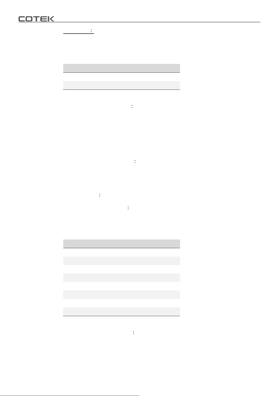
Example2
When user setting value= Disable, the SD-series “Output frequency” is
within the range of 47 Hz~63 Hz, the internal transfer relay will close.
Default= 7Hz
Model Setting value range
110 V 0 ~ 7 Hz
230 V 0 ~ 7 Hz
Table 37. Sync Frequency <FUNC8>
10. Overload Alarm <FUNC9> Set the overload alarm. When the SD-series
output power is higher than the set value, the SD-series will sound a “beep”
to remind you that the unit is going to shut-down. At the same time, the
internal Dry Contact Relay will open/close.
Default = 104%
Setting range = 50%~110%
11. Shut-down retry <FUNC10>
When SD-series is shut-down under OVP, UVP,
Overload or short circuit conditions, the inverter will automatically try to
restart according to the setting value.
Default = 5
Setting range 0 ~ 15
12. Saving Level <FUNC11> Setting the SD-series to power saving to reduce
consumption from the batteries.
Default = 0
Setting range = 0 ~ 7
Setting Value Status
0 Default
1 2%
23%
3 4%
45%
5 6%
38
67%
7 8%
Table 38. Saving Level <FUNC11>
13. Saving Interval <FUNC12> When SD-series inverter enters power saving
mode, it will detect AC Load periodically.
Default = 2.0 Seconds
Setting range = 1.0S ~ 2.0S
Page 43
6. RS-232 Command
If the AC Load is 3 times higher than Saving Level, inverter will recover and
output normally to AC Load.
14. Bypass Relay <FUNC13> The setup is provided in one of the following two
ways.
On-line Mode or Off-line Mode ( Exacting, Normal, Haphazard).
Default = Normal (Off line).
Model SETT <value>
Haphazard 0
Normal 1
Exacting 2
On-line 3
Transfer Relay
Switching Feature
The transfer relay will switch “ON” or “OFF”.
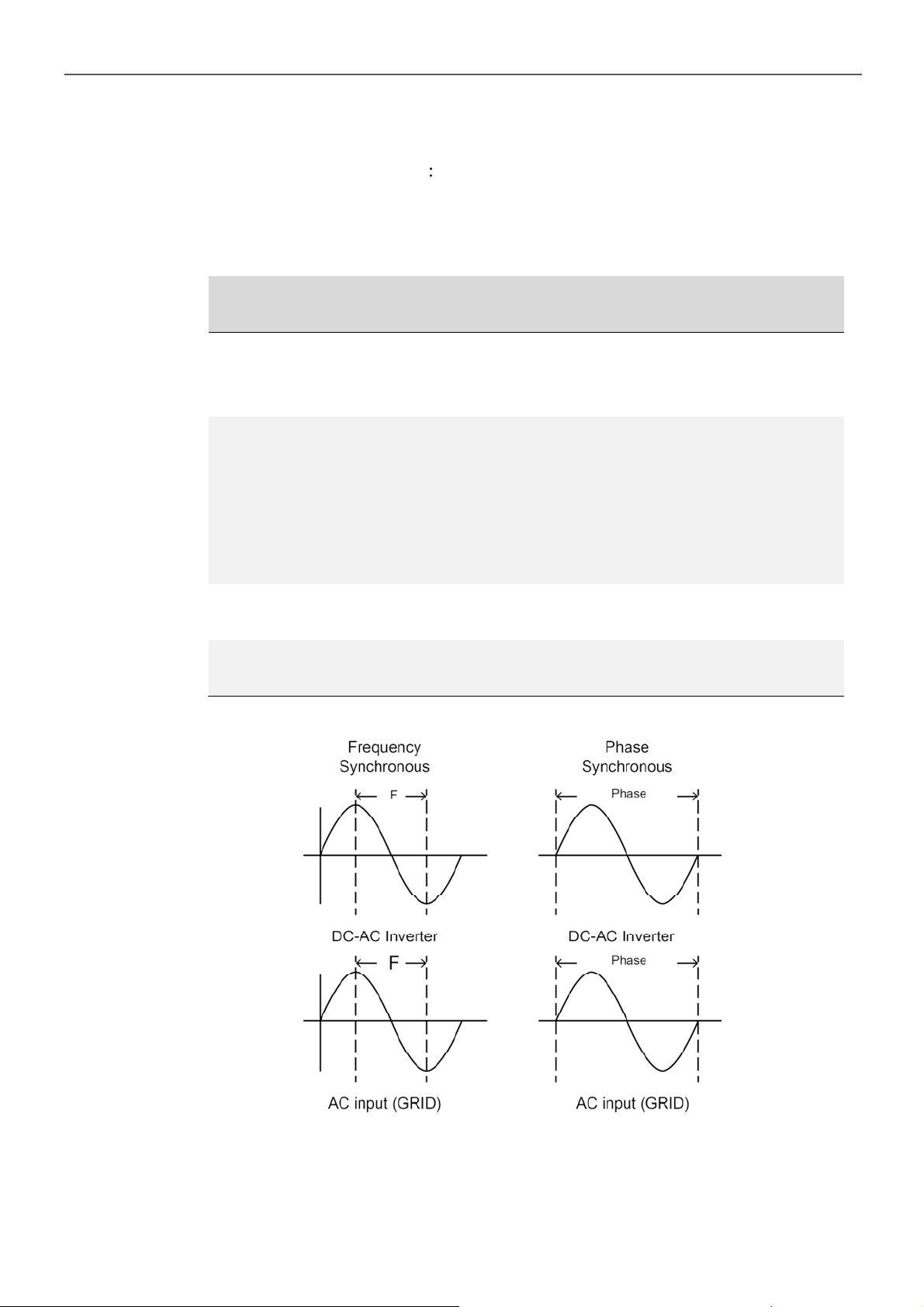
Conformance to, phase and frequency
synchronization will not be considered.
The transfer relay will be “ON” if AC input (Grid)
power is available. The DC-AC inverter will remain
synchronized and Phase with the incoming AC power
(Grid). The relay will NOT switch off if the grid
frequency is beyond the range set under Sync
Frequency window.
The transfer relay will switch “ON” or “OFF” based on
conformance to, the Phase and Sync Frequency.
Always supplied by battery until which has run down
(UVP) then switch to grid.
Table 39. Bypass Relay <FUNC13>
Figure 34. Frequency and phase synchronous
39
Page 44
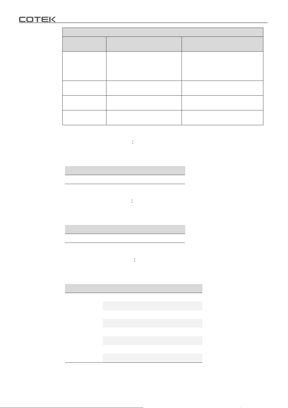
Transfer-Time Table
Mode
Transfer Switch
Haphazard
Normal
Exacting
Online
Inverter to utility AC: 8~10ms.;
Utility AC to inverter: 16~50ms.
Inverter to utility AC: 8~10ms.;
Utility AC to inverter: 16~25ms.
Inverter to utility AC: 8~10ms.;
Utility AC to inverter: 16~50ms.
Inverter to utility AC: 8~10ms.;
Utility AC to inverter: 16~25ms.
ATS STS
Frequency is synchronized: < 4ms.;
Frequency is not synchronized:
Inverter to utility AC: < 4ms.;
Utility AC to inverter: 16~50ms.
Inverter to utility AC: < 4ms.;
Utility AC to inverter: 16~50ms.
Table 40. SD series transfer time
15. LCD contrast <FUNC14> Sets the LCD screen contrast.
Default = 50%
Setting range = 0% ~ 100%
Setting Menu Status <value>
LCD Contrast 0 ~ 100
< 4ms
< 4ms
Table 41. LCD contrast <FUNC14>
16. LCD Auto-off <FUNC15> Sets the LCD screen backlight auto off timer.
Default = 120 seconds
Setting range = 0 ~ 120 seconds.
Setting Menu Status <value>
LCD Auto-off 0 ~ 120
Table 42. LCD Auto-off <FUNC15>
17. Buzzer setting <FUNC16> Set the LCD remote control for the buzzer sound
Default = MSG, Alert, SHDN
Setting range = 0~7
Setting Menu SETT <value> Buzzer (Beep sound)
0 Disable
1 SHDN
2Alert
Buzzer Setting
3 Alert , SHDN
4MSG
40
5 MSG , SHDN
6 MSG , Alert
7 MSG , Alert , SHDN
Table 43. Buzzer setting <FUNC16>
Page 45
6. RS-232 Command
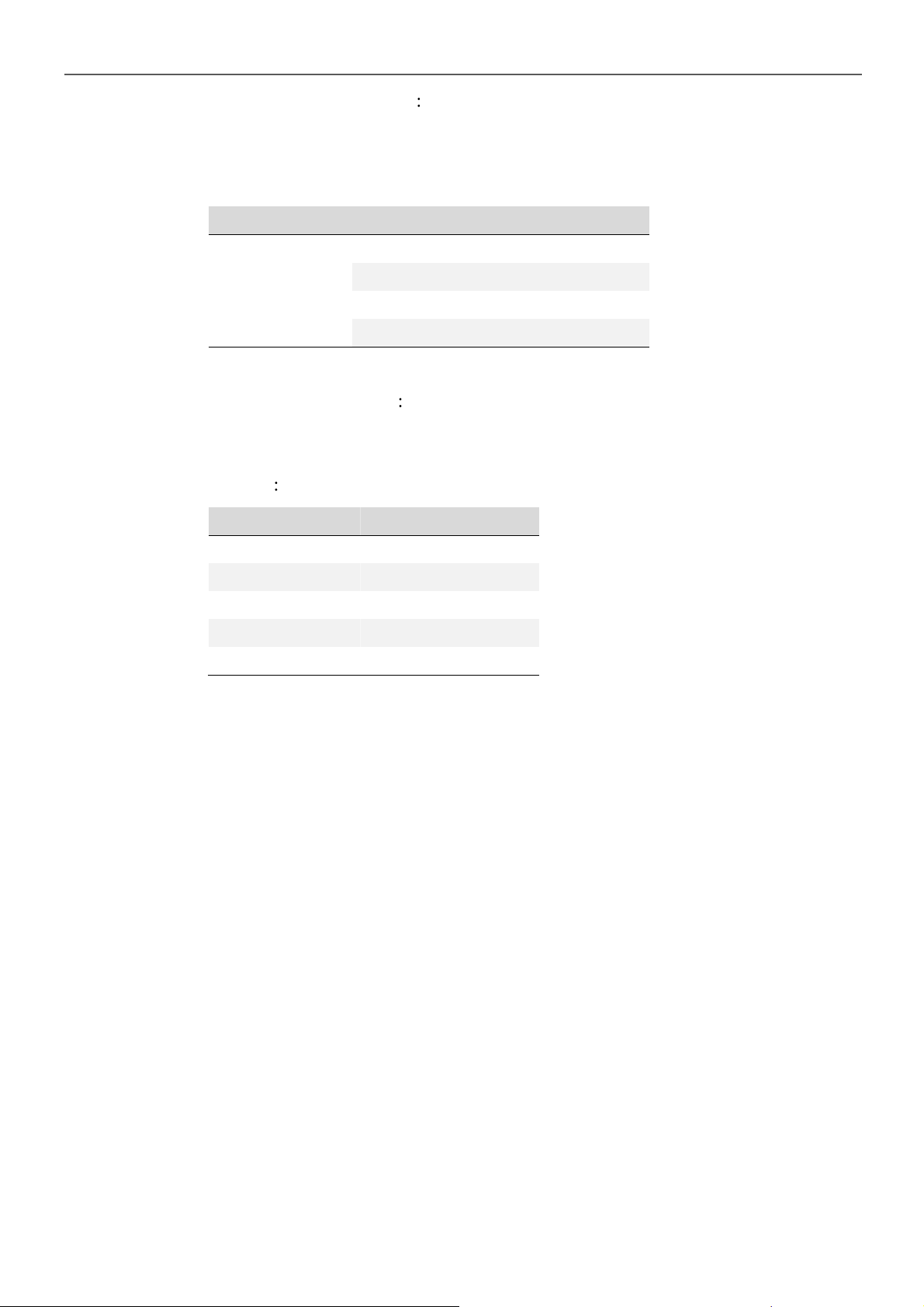
18. Alert Setting <FUNC17> When alert occurs, the internal dry contact relay
will open/close.
Default = Alert, SHDN
Setting range = 0~3
Setting Menu SETT (RS-232) Alert (LCD)
0 Disable
Buzzer Setting
Table 44. Alert Setting <FUNC17>
1 SHDN
2Alert
3 Alert , SHDN
19. Language <FUNC18> The SD-series have different languages available
and are selectable.
Default = English
Setting English / Italian / Spanish / French / German
Model Setting value
English 0
Italian 1
Spanish 2
French 3
German 4
Table 45. Language <FUNC18>
41
Page 46
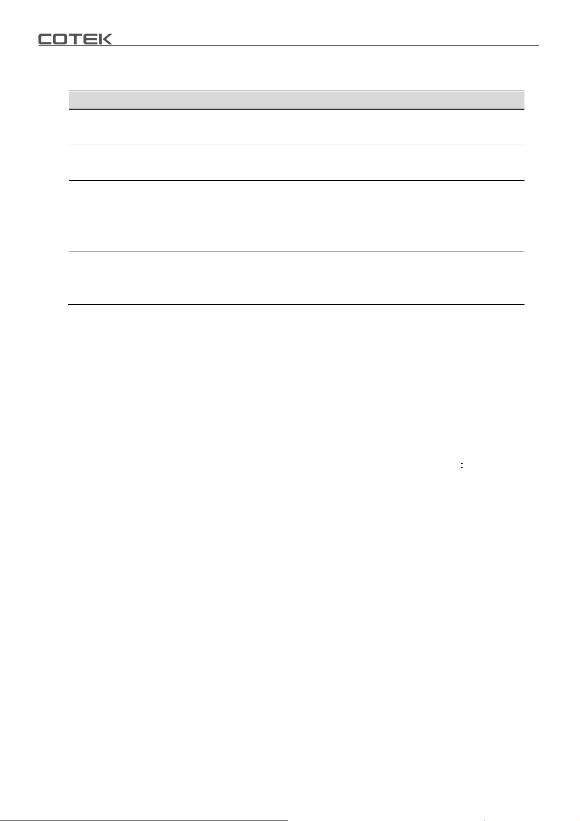
7.Troubleshooting
Problems and Symptoms Possible Cause Solutions
A. Power status red light is
blinking fast.
B. Power status red light is
Blinking slowly.
C. Power status red light is
blinking Intermittently.
D. Power status is solid red
Over input voltage. (OVP)
Low input voltage. (UVP)
Thermal shut-down. (OTP)
Short circuit.
Wiring error.
Over Loading (OLP)
Table 46. SD series Troubleshooting
Check input voltage.
Reduce input voltage.
Recharge battery. Check connections
and cables.
Improve ventilation. Make sure
ventilation, shafts of the inverter are
not obstructed. Lower ambient
temperature.
Check AC wiring for short circuit.
Reduce load.
8.Warranty
We guarantee this product against defects in materials and workmanship for a period of
24 months from the date of purchase. Please contact with your local COTEK authorized
distributor for RMA (Return material Authorization) service. Please note that COTEK will
ensure our products are operational before delivery and the warranty service is offered to
the unit which has defect caused under normal use, in the judgment of COTEK’s
technician. The warranty is null and void under the following circumstances
(a) If the unit has been damaged through abuse, misuse, negligence (such as bumping,
wetting), fault voltage supply, air/water pollution accidents and natural calamities.
(b) If the serial number has been altered, effaced or removed.
42
Page 47

Page 48

No. 33, Sec. 2, Renhe Rd., Daxi Dist., Taoyuan City 33548, Taiwan
Phone
+886-3-3891999 FAX +886-3-3802333
http
// www.cotek.com.tw
2016.07._A7
 Loading...