

Page 1
文管中心
發行章
料號:75-1000-0012_A4
原版別:75-1000-0012_A3
尺寸:A5
印刷:黑白正反面印刷
材質:一般書寫紙
*改版原因:
-修正page.2-Copyright logo亂碼
-庫存自然淘汰
※以上敘述非本文※
2011.04.12
研發部
簡世宗
正式文件,妥善保存
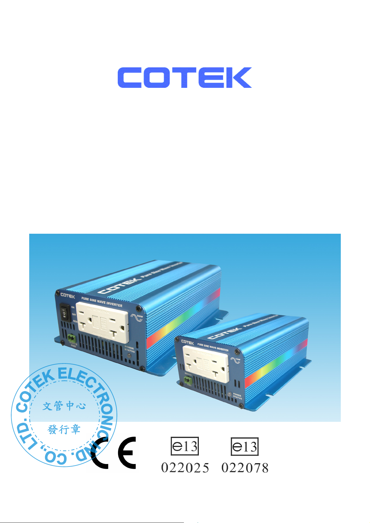
S150,S300 Series
Pure Sine Wave Inverter
User’s Manual
Page 2
文管中心
發行章
List of contents
1. IMPORTANT safety Information…………………………………………... 1
1-1 General Safety Precautions………………………………………….. 1
1-2 Battery Precautions…………………………………………………… 1
2. Features………………………………………………………………………. 2
2-1 Electrical Performance 150W……………………………………….. 2
2-2 Electrical Performance 300W……………………………………….. 3
2-3 Mechanical Drawing 150W………………………………………….. 4
2-4 Mechanical Drawing 300W………………………………………….. 5
3. Instructions………………………………………………………………….. 6
3-1 Front Panel Operation……………………………………………….. 6
3-2 Rear Panel Operation………………………………………………... 6
3-3 AC Safety Grounding………………………………………………… 7
3-4 Installation…………………………………………………………….. 8
3-5 DC Input (Outlet sockets available)………………………………… 9
3-6 AC Output (Outlet sockets available)………………………………. 9
3-7 ON / OFF / REMOTE Main Switch.………………………………… 10
4. Troubleshooting……………………………………………………………. 11
5. Maintenance………………………………………………………………… 12
6. Warranty…………………………………………………………………….. 12
7. Appendices…………………………………………………………………. 13
7-1 FCC (Class B) declaration of conformity………………………….. 13
7-2 CE (ENC EN55022) declaration of conformity…………………… 14
7-3 CE (LVD EN60950) declaration of conformity……………………. 15
7-4 e-mark S150 (e13 022025) declaration of conformity…………… 16
7-5 e-mark S300 (e13 022078) declaration of conformity…………… 17
7-6 UL (UL458) notice of compliance………………………………….. 18
1
©Copyright :This manual is the copyright of COTEK Electronic Ind. Co., Ltd. And may not be reproduced or copied
without the express permission of the owner.
Page 3
文管中心
發行章
1. Important Safety Information
1-1. General Safety Precautions
1-1-1. Do not expose the Inverter to water, mist, snow, or dust. To reduce
the risk of hazard, do not cover or obstruct the ventilation shaft.
Do not install the Inverter in a zero-clearance compartment.
Overheating may occur.
1-1-2. To avoid the risk of fire and electronic shock, make sure that existing
wiring is in good electrical condition and not undersize.
Do not operate the Inverter with damaged or substandard Wiring.
1-1-3. There are some components in the inverter can cause arcs and sparks.
To prevent from fire or explosion, do not put batteries, flammable
materials, or anything should be ignition–protected around the inverter.
WARNING!
Before installing and using the Inverter, you need to read
following safety information carefully.
1-2. Precautions When Working with Batteries
1-2-1. If battery acid contacts your skin or clothing, you need to wash it out
immediately with soap and water. If acid enters into your eyes,
immediately flush your eyes with running cold water for at least 20
minutes and get medical attention immediately.
1-2-2. Never smoke or make a spark or flame in the vicinity of batteries or
Engines.
1-2-3. Do not drop a metal tools on the battery. The resulting spark or short-
circuit on the battery or other electrical parts may cause an explosion.
1-2-4. Remove personal metal items such as rings, bracelets, necklaces, and
watches when working with a lead-acid battery,
A lead-acid battery may produce a short-circuit current who’s
temperature is high enough to weld these metal items and cause a
severe burn.
1
Page 4
文管中心
發行章
2. Features
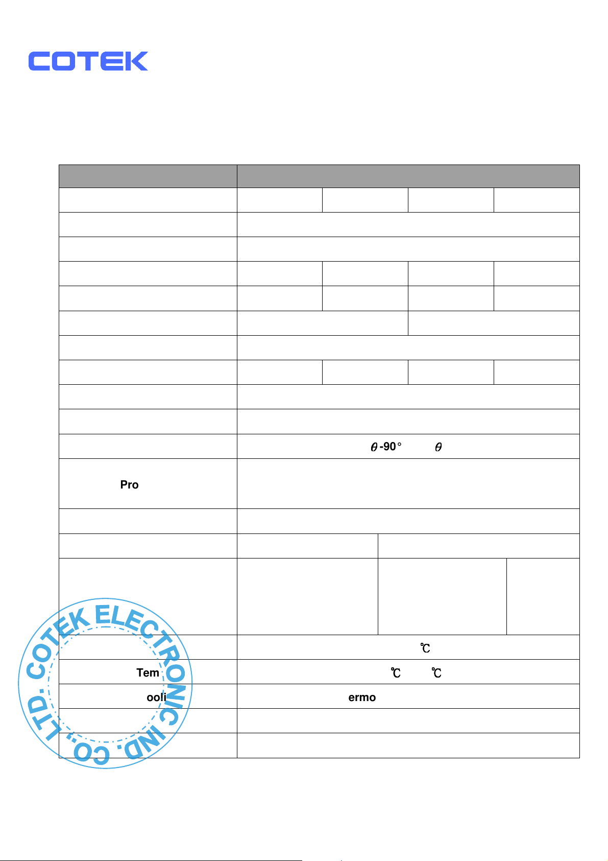
2-1. Electrical Performance 150W
Specification
Item S150-112 S150-124 S150-212 S150-224
Continuous Output Power 150W
Surge Rating 200W
Input voltage 12V 24V 12V 24V
Input voltage Range 10.5 – 15.0 21.0 – 30.0 10.5 – 15.0 21.0 – 30.0
Output Voltage
Frequency
Max. Efficiency 87% 88% 87% 88%
No Load Current Draw <0.3A
Output Waveform Pure Sine Wave ( THD 6.0% Typical )
Power Factor Allowed
110VAC ±5% 230VAC ±5%
Model No.
50 / 60Hz ±0.3%
cos
θθθθ
-90° ~ cos
θθθθ
+90°
Protection
Remote Control Yes, On/Off controlled by external switch
Safety Certification UL458 EN60950-1
EMC FCC Class B
Operating Temperature
Storage Temperature
Fan Cooling Thermostatically controlled
Dimensions 200(L) x 132(w) x 72(H) mm / 7.87(L) x 5.20(W) x 2.83(H) Inch
Weight 2.7 kgs. / 5.4 Lbs.
Overload, Short Circuit, Reverse Polarity (Fuse),
Over / Under Input Voltage, Over Temperature.
EN55022:1997
EN61000-3-2:1998
EN61000-3-3:1995
EN55024:2001
0 – 40
-30
℃℃℃℃
℃℃℃℃
to 70
℃℃℃℃
e-mark
e13 022025
Note: The specifications are subject to change without notice.
2
Page 5
文管中心
發行章
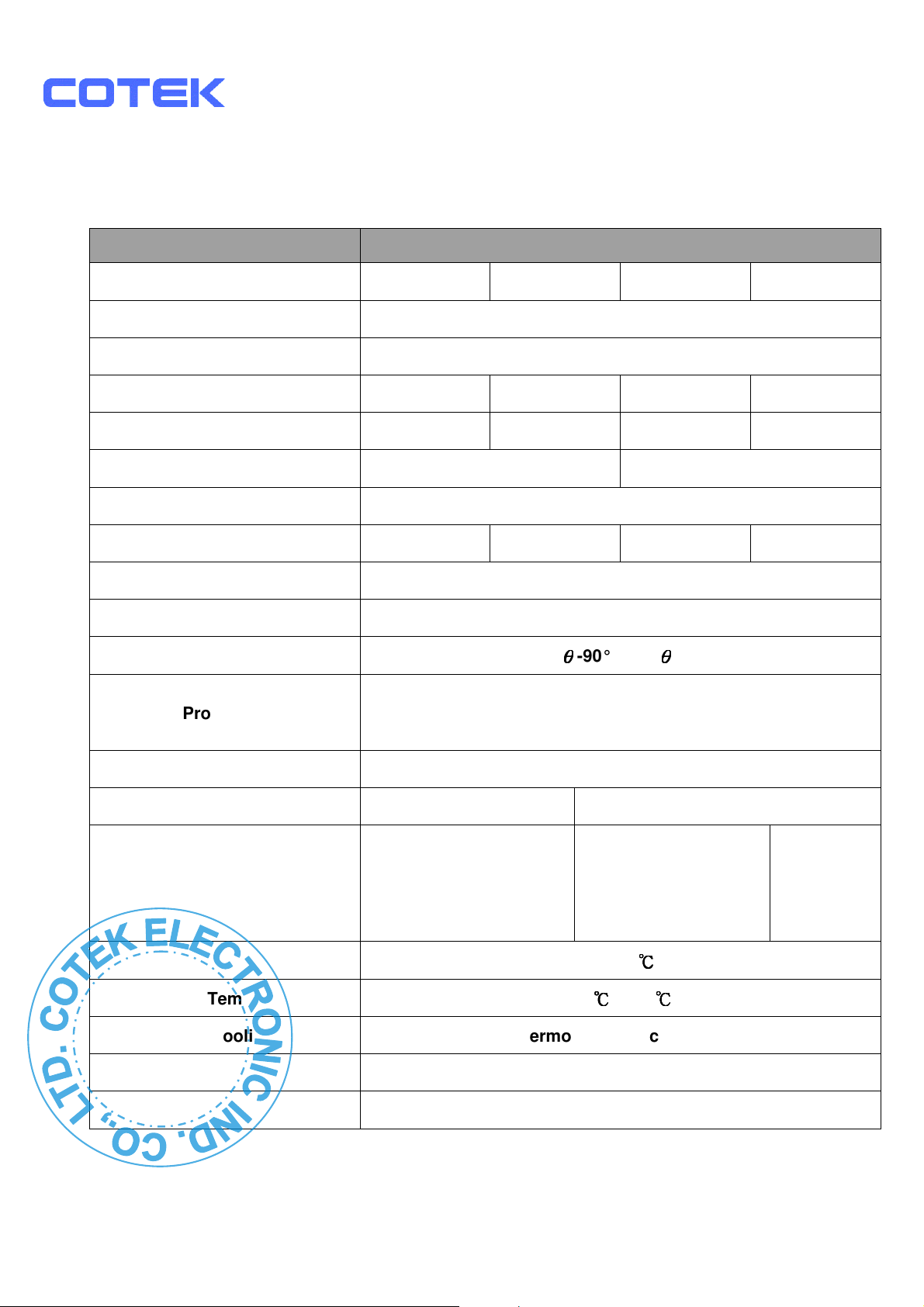
2-2. Electrical Performance 300W
Specification
Item S300-112 S300-124 S300-212 S300-224
Continuous Output Power 300W
Surge Rating 400W
Input voltage 12V 24V 12V 24V
Input voltage Range 10.5 – 15.0 21.0 – 30.0 10.5 – 15.0 21.0 – 30.0
Output Voltage
Frequency
Max. Efficiency 89% 89% 89% 89%
No Load Current Draw <0.35A
Output Waveform Pure Sine Wave ( THD 6.0% Typical )
Power Factor Allowed
110VAC ±5% 230VAC ±5%
Model No.
50 / 60Hz ±0.3%
cos
θθθθ
-90° ~ cos
θθθθ
+90°
Protection
Remote Control Yes, On/Off controlled by external switch
Safety Certification UL458 EN60950-1
EMC FCC Class B
Operating Temperature
Storage Temperature
Fan Cooling Thermostatically controlled
Dimensions 237(L) x 155(w) x 72(H) mm / 9.33(L) x 6.10(W) x 2.83(H) Inch
Weight 3.5 kgs. / 7.7 Lbs.
Overload, Short Circuit, Reverse Polarity (Fuse),
Over / Under Input Voltage, Over Temperature.
EN55022:1997
EN61000-3-2:1998
EN61000-3-3:1995
EN55024:2001
0 – 40
-30
℃℃℃℃
℃℃℃℃
to 70
℃℃℃℃
e-mark
e13 022078
Note: The specifications are subject to change without notice.
3
Page 6
文管中心
發行章
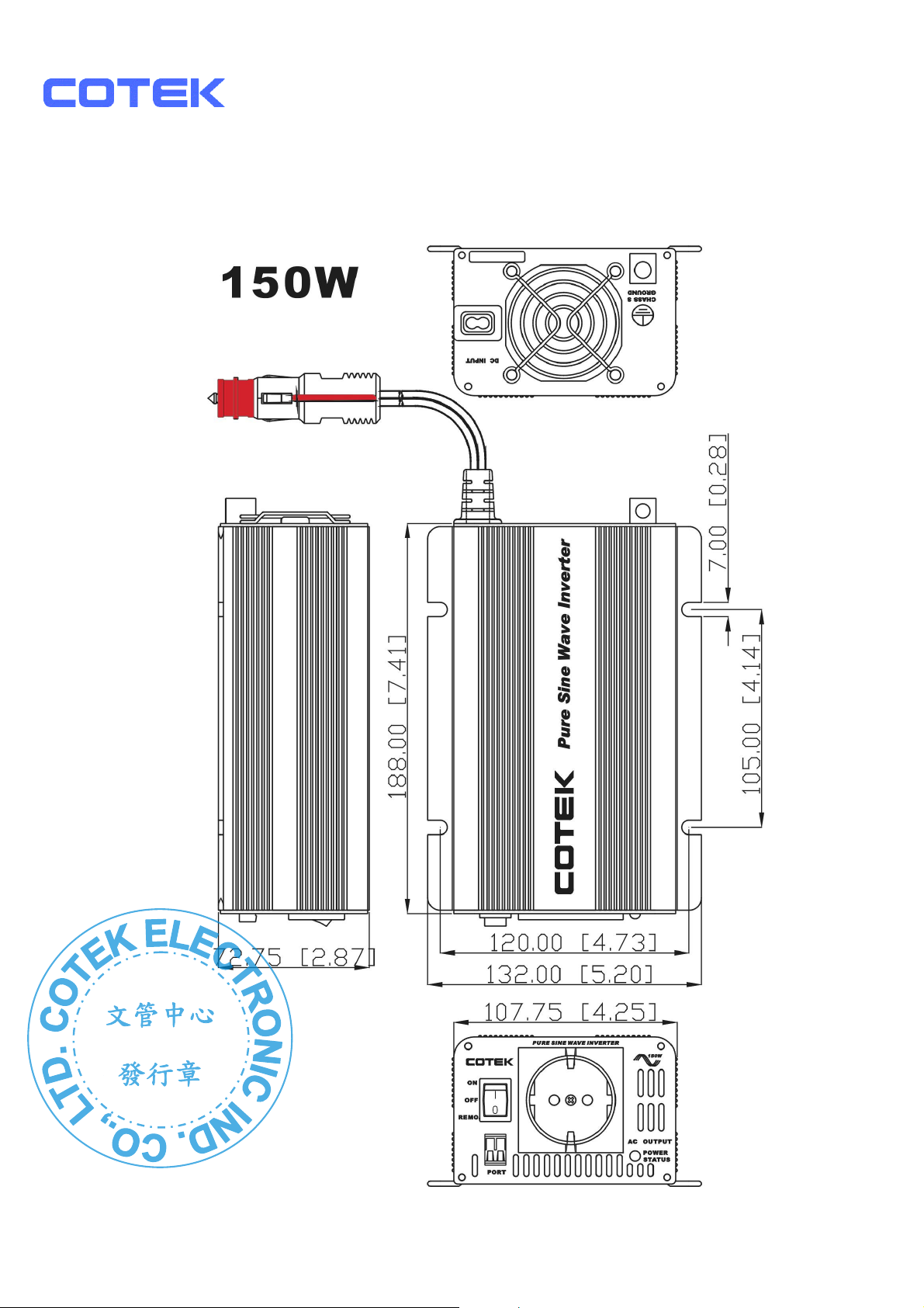
2-3. Mechanical Drawing
4
Page 7
文管中心
發行章
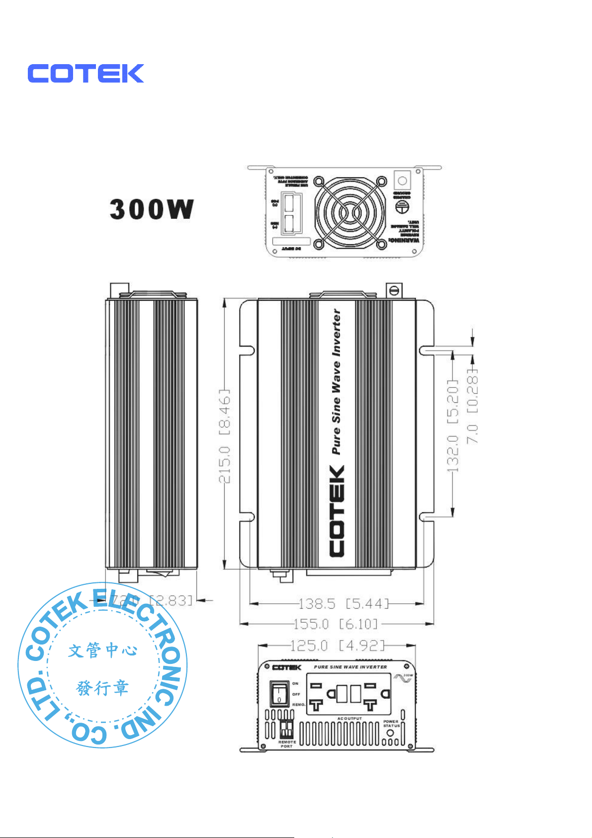
2-4. Mechanical Drawing
5
Page 8
文管中心
發行章
3. Instructions
S150 and S300 series are very reliable, portable, and fully protected. These
pure sine inverters are used in a wide range of applications such as mobiles,
office equipments, home entertainment, electronic appliances, etc.
To get the most effective power inverter, it must be installed and used properly.
Please read the instructions of this manual before you install and operate this
model.
3-1. Front Panel Operations
3-1-1. ON / OFF REMOTE switch:
Leave the switch in the down position (OFF) during installation.
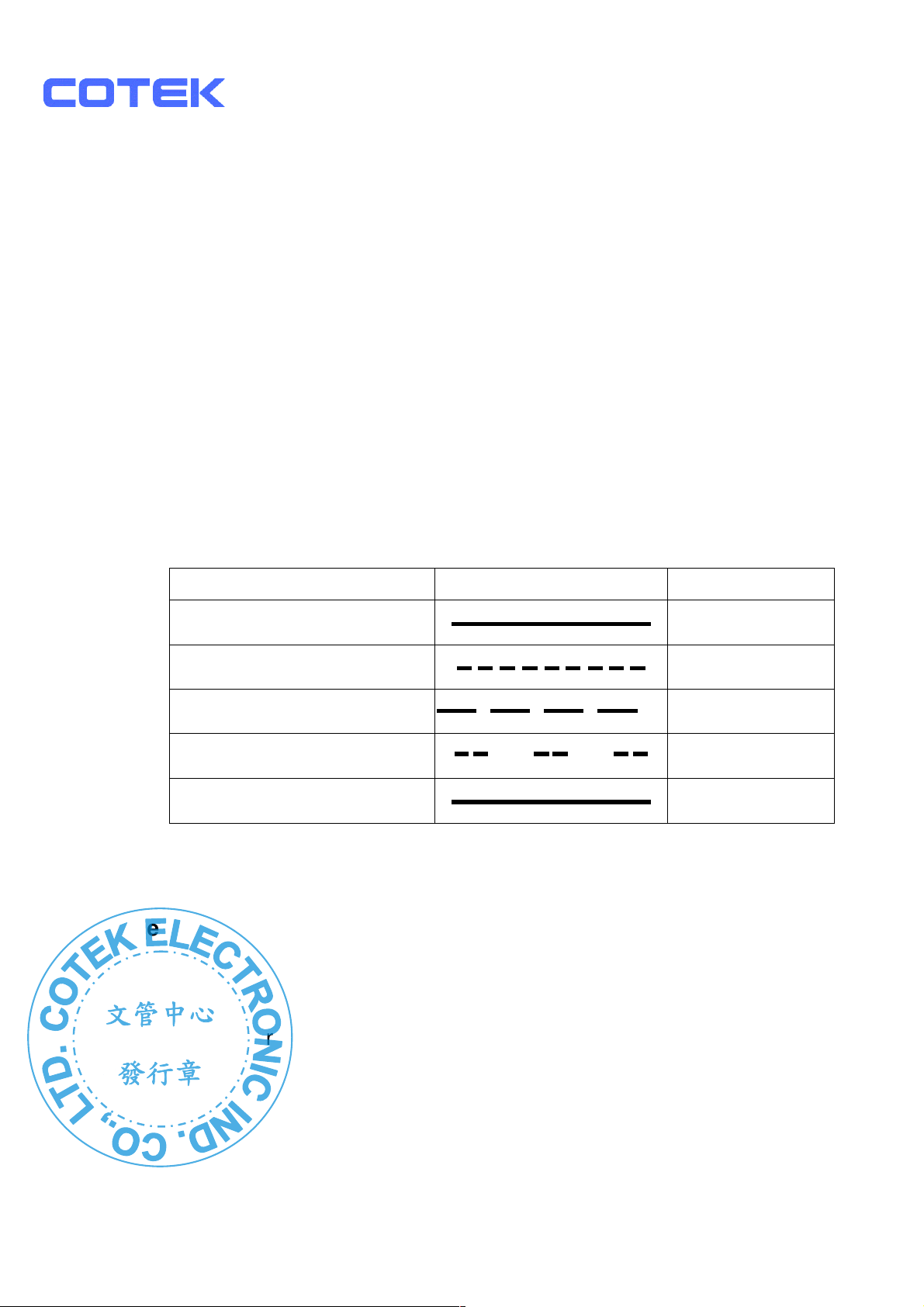
3-1-2. LED display indicates Power Status
LED Conditions Status
Solid Green
Fast Red Blink
Slow Red Blink
Intermittently Red Blink
Solid Red
3-1-3. Remote Port:Place 0.75mm2 and Screw type cable between the
remote port and the panel.
3-2. Rear Panel Operations
3-2-1. Ventilation shaft:Keep the ventilation shaft a distance (at least 3 inch)
from anything surrounding it
AC Power OK
OVP
UVP
OTP
OLP
3-2.2. Input terminals:Connect the input terminal to 12v / 24V / 48V battery
3-3-3. Use wire # 8 AWG to connects Chassis ground with Vehicle Chassis.
or other 12V / 24V / 48V power source. 【+】
represents positive, and【-】represents negative.
Reverse polarity connection will blow the internal fuse
and may damage inverter permanently.
6
Page 9
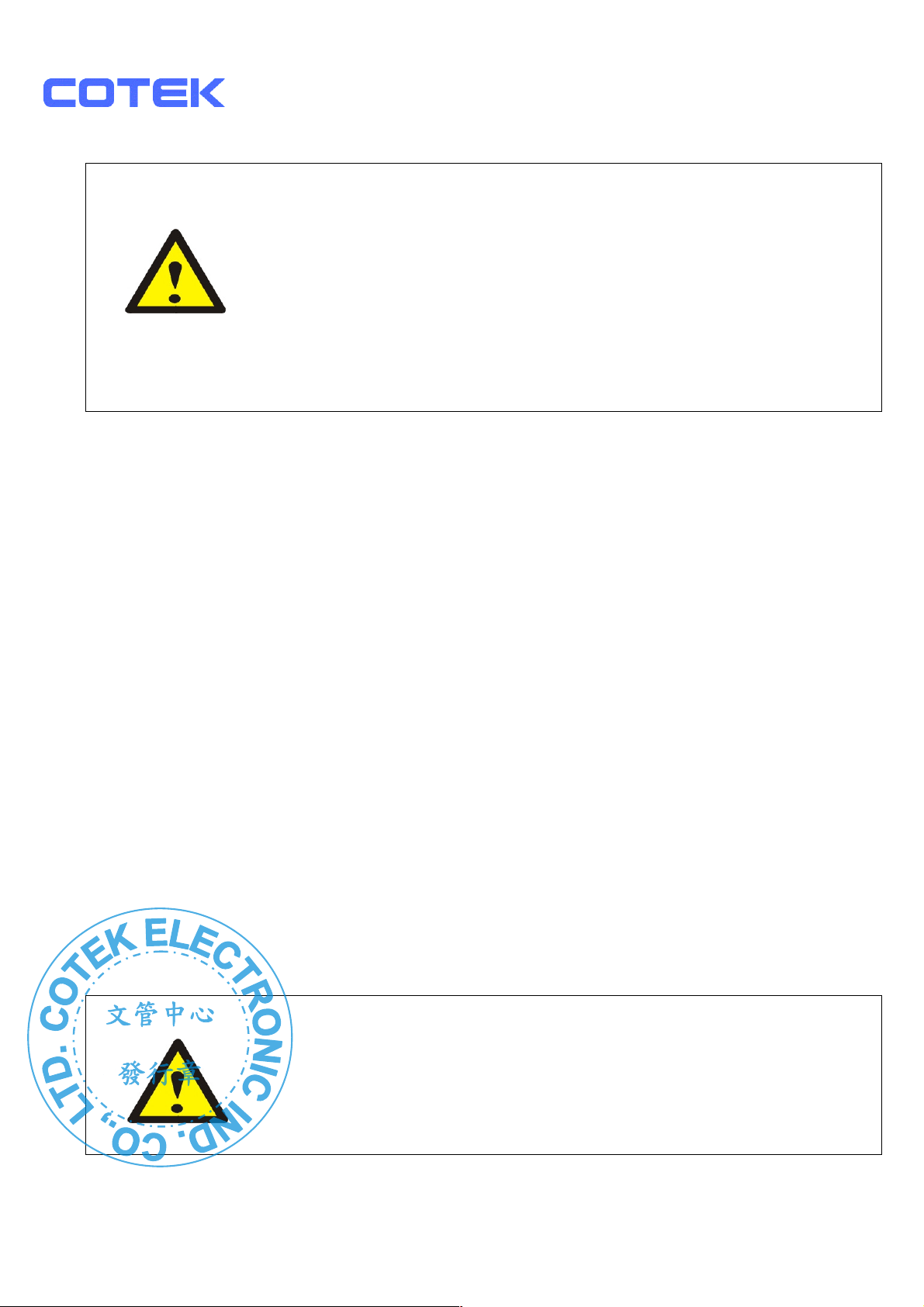
Do not combine the 12V model with 24V battery or the unit will
文管中心
發行章
WARNING!!!!
be destroyed immediately.
Operate with the inverter without a proper ground connection
may cause an electrical safety hazard.
Damage caused by reversed polarity is not covered by the
warranty. Ensure the power switch is in the OFF position
before putting the battery in.
3-3. AC Safety Grounding::::
During AC wiring installation, AC input and output ground wires are
connected to the inverter. The AC input ground wire must connected to the
incoming ground from AC utility source.
The AC output ground wire should go to the grounding point for your loads
( for example, a distribution panel ground bus ).
3-3-1. Neutral Grounding (GFCI’S):
110V models:The neutral conductor of the AC output circuit of the
Inverter is automatically connected to the safety ground during inverter
operation. This conforms to National Electrical Code requirements
that separately derived from AC sources (such as inverters and
generators) which have their neutral conductors tied to ground in the
same way as the neutral conductors from the utility tied to ground at
the AC breaker panel. For models configured with a transfer relay,
while AC utility power is present and the Inverter is in bypass mode,
this connection (the neutral of the Inverter’s AC output to input safety
ground) is not present so that the utility neutral is only connected to
ground at your breaker panel, as required. Cotek has tested the
following GFCI-properly when connected to the output of the Inverter.
WARNING!!!!
Never connect the inverter’s output to the AC distribution grid,
such as the household AC wall outlet.
It will damage the Inverter.
7
Page 10
文管中心
發行章
3-4. Installation
Before connecting your applications to the inverter, always check the power
draw of your appliances. The inverter can supply surge power for a short
time so as to start up the electrical equipment such as motors, pumps… that
need more power while starting up.
When all the above requirements are checked OK and satisfied and all
connections are made, it’s time to turn on the inverter by switching the power
to ‘ I ’ position. The sine wave filters provide sine wave output voltage when
driven from AC outlet.
To save the battery power, you are highly recommended to turn off the
inverter when it is not used.
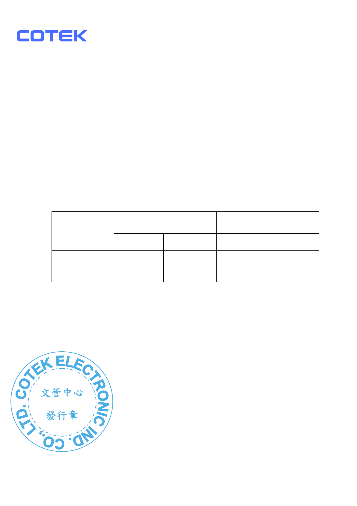
DC input voltage status as follows:
Model
DC Input Over
Voltage
Shut-down
Restart Shut-down
DC Input Under
Voltage
Restart
12V models 15.3 14.8 10.5 12.5
24V models 30.6 29.6 21.0 25.0
8
Page 11
文管中心
發行章
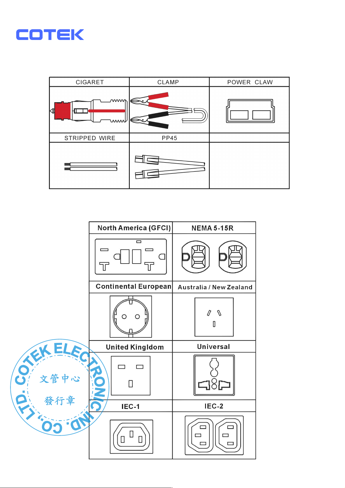
3-5. DC Input (Outlet sockets available)::::
3-6. AC output (Outlet Sockets available)::::
9
Page 12
文管中心
發行章
3-7. ON / OFF / REMOTE Main Switch.
3-7-1. Before installing the inverter, make sure the main switch must
be “OFF”.
3-7-2. Before using the remote unit, make sure the main switch must
be “ REMOTE”.
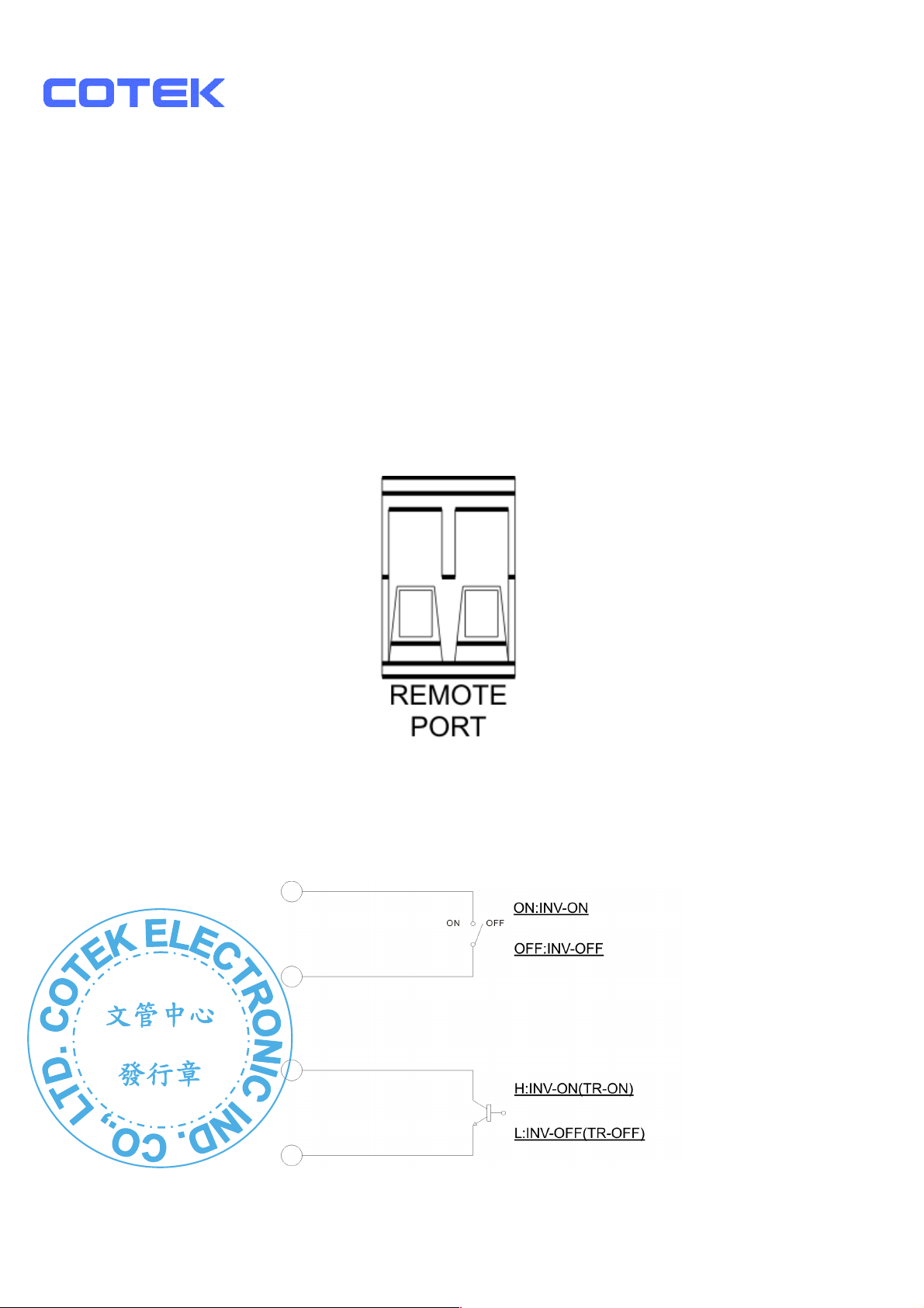
3-7-3. Ensure the remote control contact is off.
2
3-7-4. Remote Port:Place 0.75mm
and Screw type cable between
the remote port and the panel.
3-7-5. Remote port ON/OFF inverter setup status
REMOTE PORT
ODE Ⅰ
M
MODE Ⅱ
1
0
Page 13
shafts in the inverter are
文管中心
發行章
4. Troubleshooting:
WARNING!!!!
Do not open or disassemble the Inverter. Attempting to
service the unit yourself may cause the risk of electrical
shock or fire.
Problems and Symptoms Possible Cause Solutions
No output voltage, the LED glows Red light.
a. Power status light is
blinking red fast.
:
::
Over input voltage. Check input voltage.
Reduce input voltage.
b. Power status light is
blinking red slowly.
c. Power status light is
blinking red intermittently.
d. Power status light is
glowing red steadily.
Low input voltage. Recharge battery.
Check connections and
cable.
Thermal shutdown Improve ventilation.
Make sure ventilation
not obstructed.
Lower ambient
temperature.
Short circuit, Wiring
error, Overload
Check AC wiring for
short circuit.
Remove load.
11
Page 14
文管中心
發行章
5. Maintenance:
Very little maintenance is required to keep your inverter operating properly.
You should clean the exterior of the unit periodically with a damp cloth to pre vent
accumulation of dust and dirt. At the same time, tighten the screws on the DC
input terminals.
6. Warranty:
We guarantee this product against defects in materials and workmanship for a
period of 24 months from the date of purchase and will repair or replace any
defective power inverters if you directly returned them to us with postage paid.
Please note that Cotek is only responsible for ensuring our products are
operational before delivering. This warranty will be considered void if the unit
has been misused, altered, or accidentally damaged. Cotek is not liable for
anything that occurs as a result of the user’s fault.
:
::
:
::
12
Page 15
文管中心
發行章
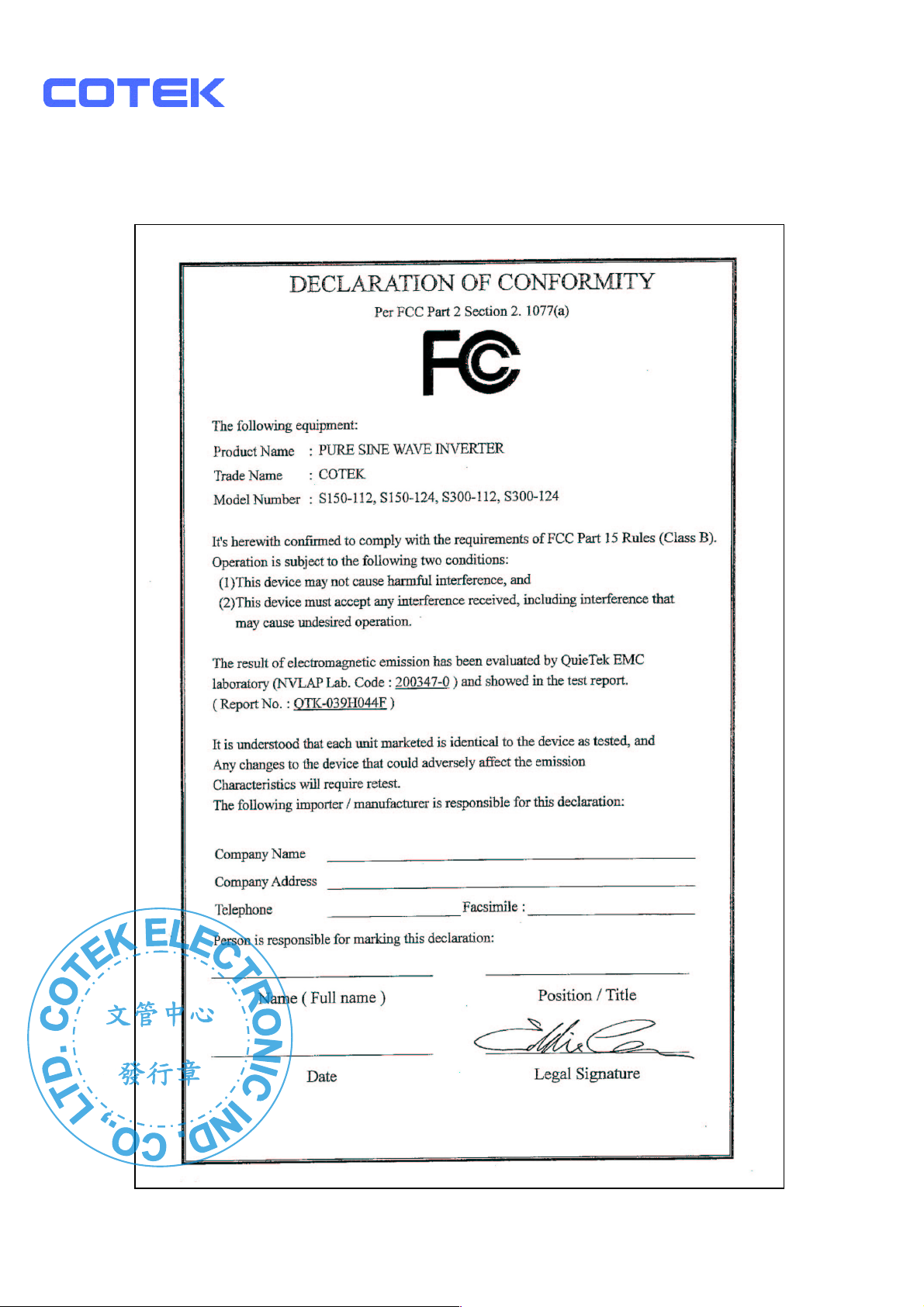
7-1. FCC (Class B) Declaration of Conformity
13
Page 16
文管中心
發行章
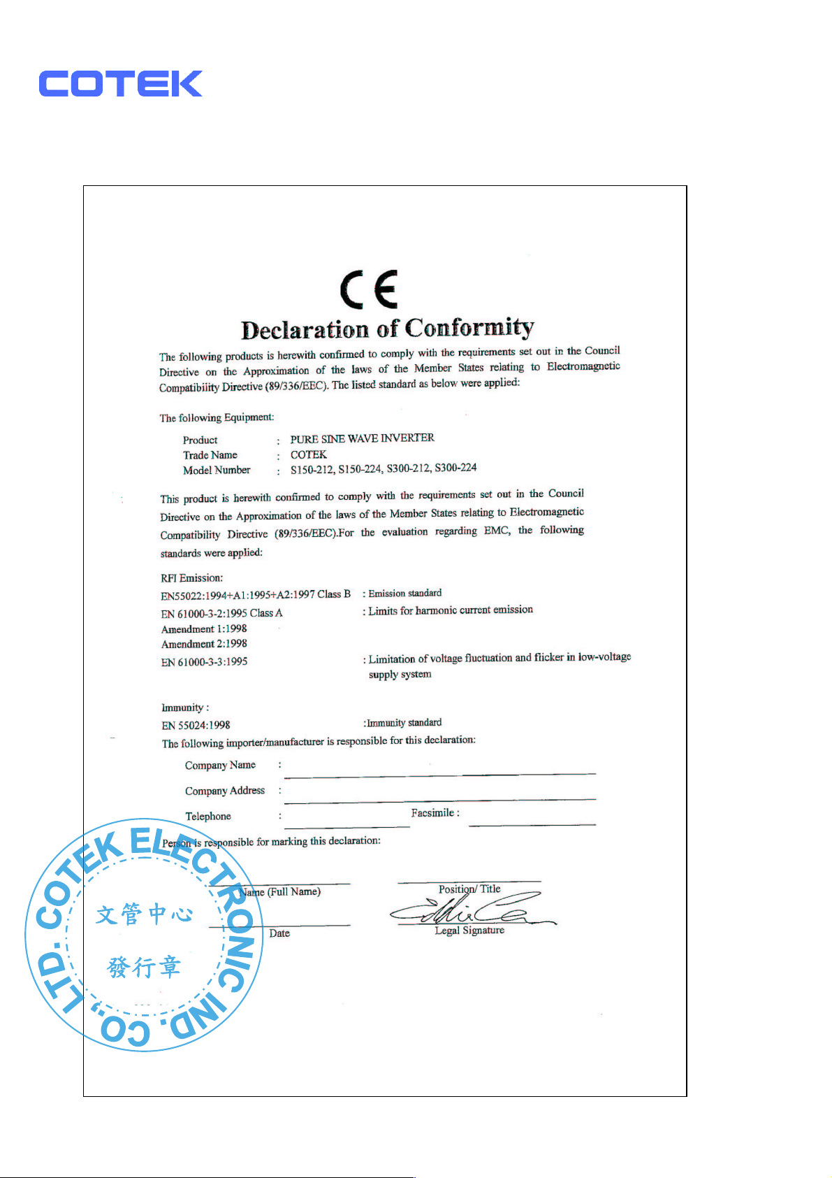
7-2. CE (EMC EN55022) Declaration of Conformity
14
Page 17
文管中心
發行章
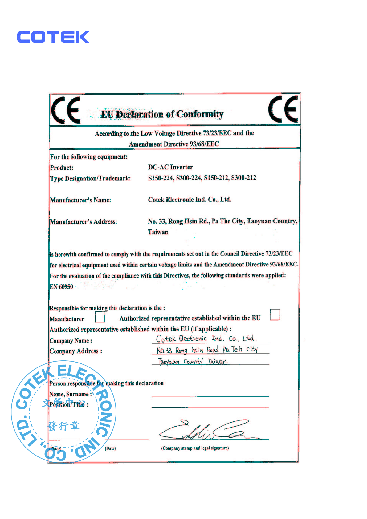
7-3. CE (LVD EN60950-1) Declaration of Conformity
15
Page 18
文管中心
發行章
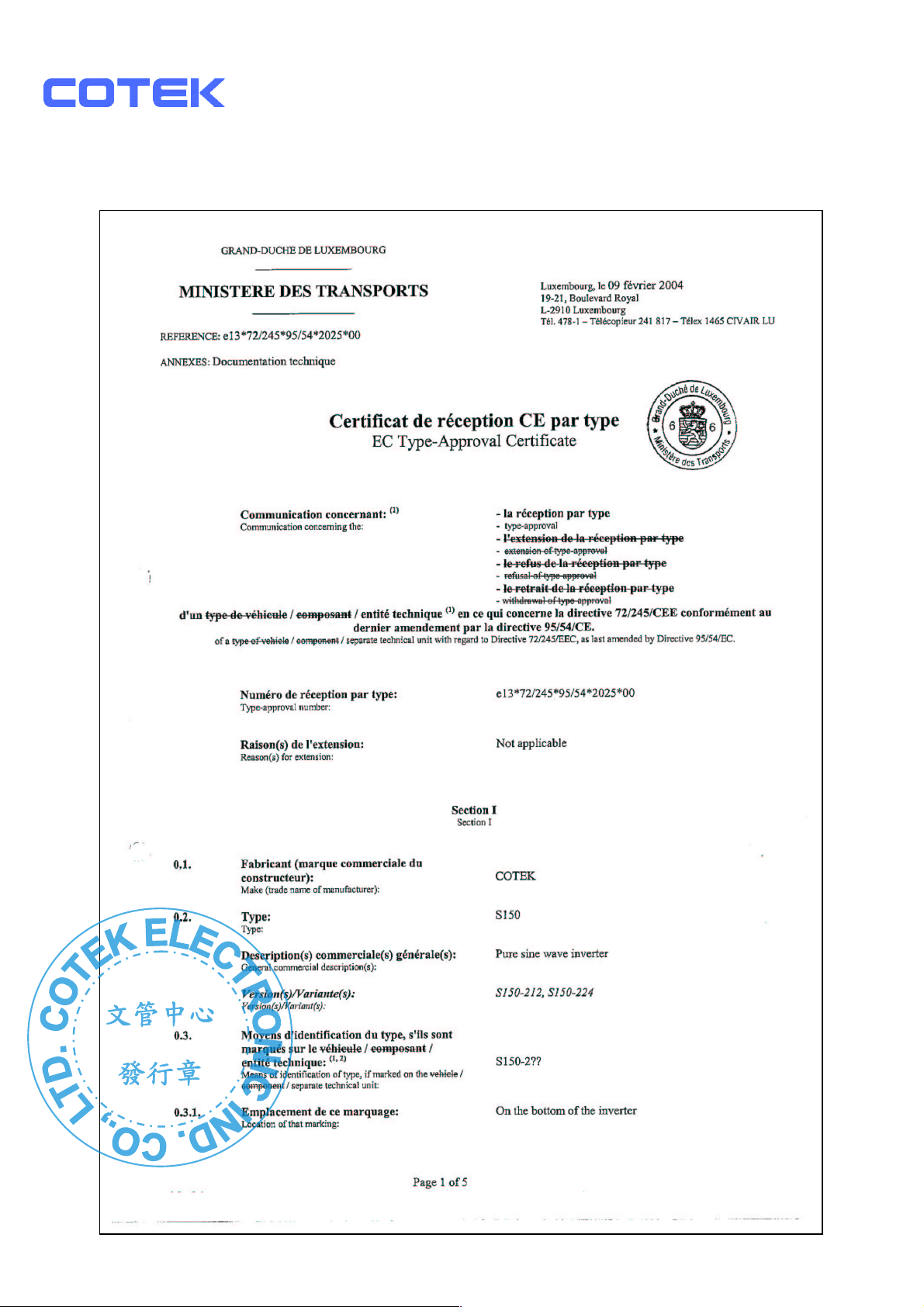
7-4. e-mark S150 (e13 022025) Declaration of Conformity
16
Page 19
文管中心
發行章
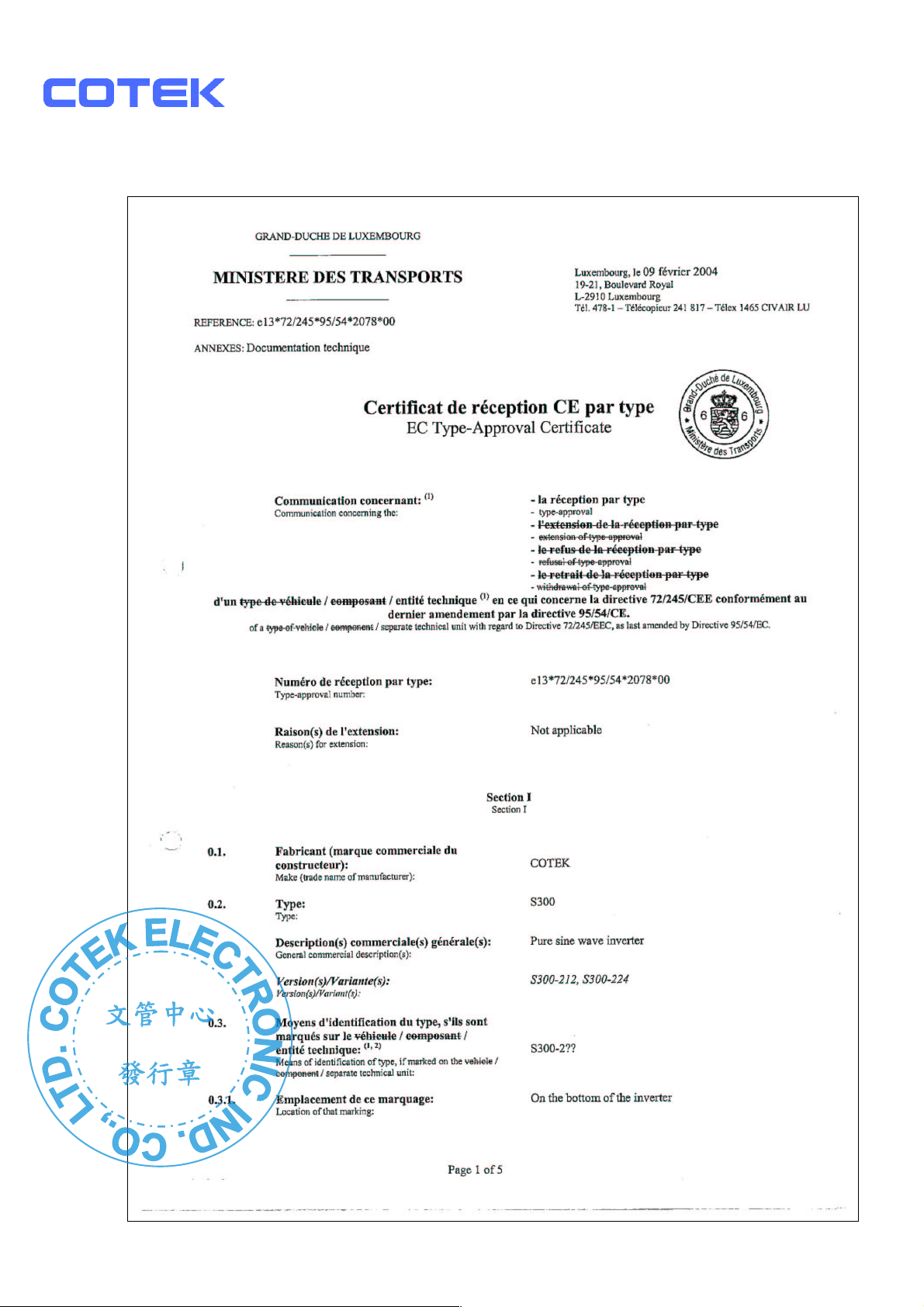
7-5. e-mark S300 (e13 022078) Declaration of Conformity
17
Page 20
文管中心
發行章
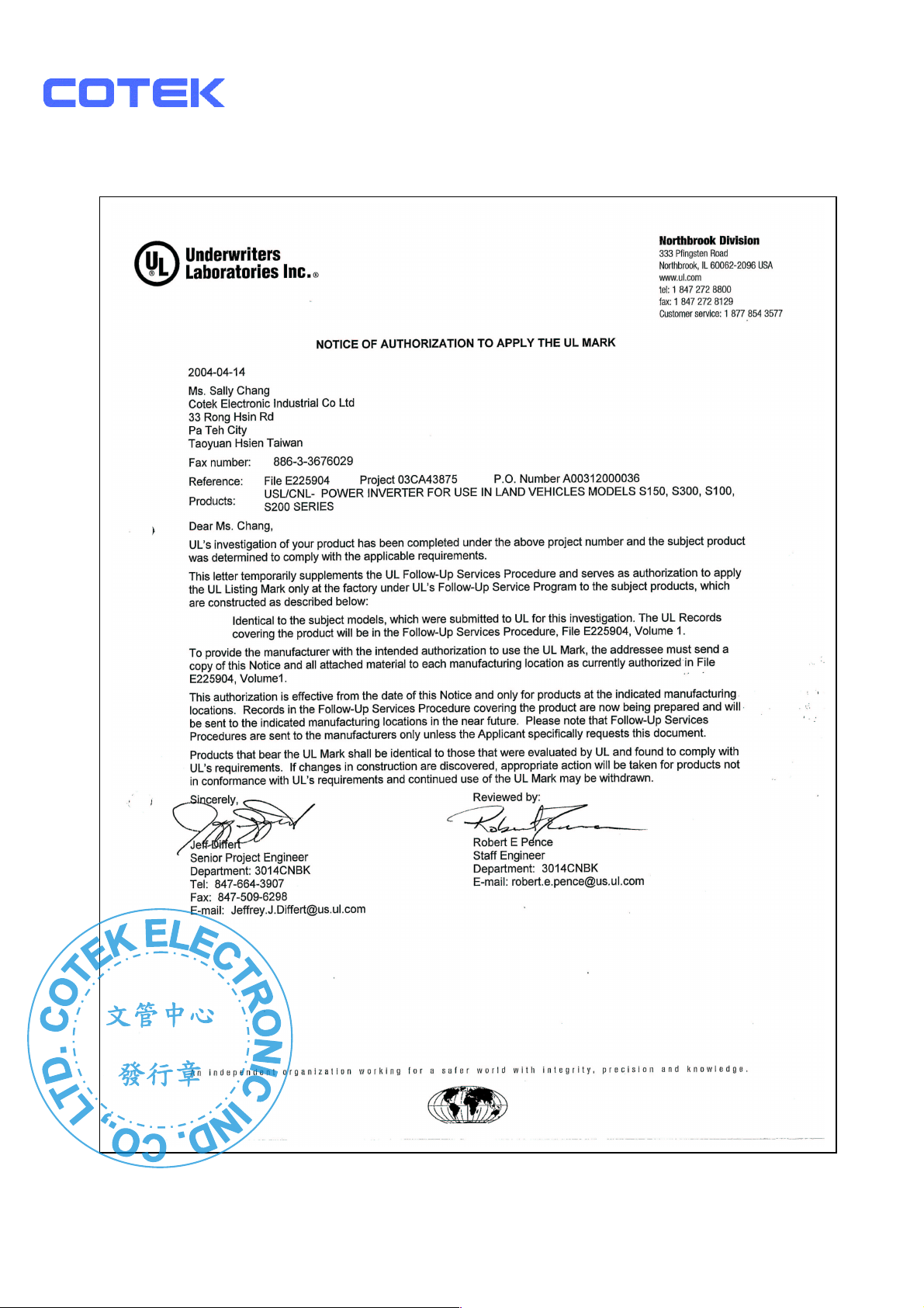
7-6. UL (UL458) Notice of Completion
18
Page 21
2011/
03
文管中心
發行章
No. 33, Rong Hsin Rd., Pa Teh City, Tao Yuan County, Taiwan
Phone::::886-3-3661581 FAX::::886-3-3676029
E
Page 22
文管中心
發行章
Page 23
 Loading...