

Page 1
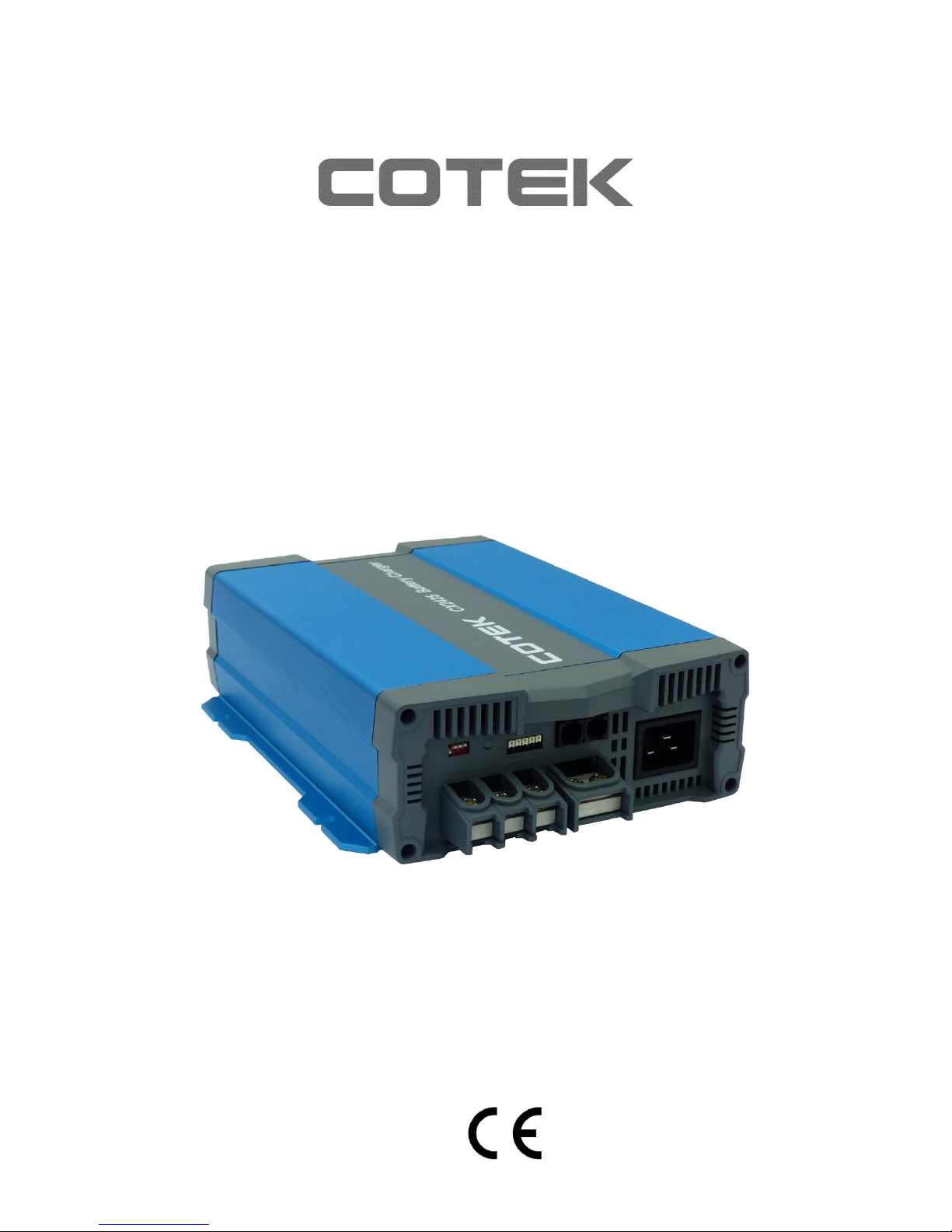
CX-SERIES
ADVANCED BATTERY
CHARGER
Page 2

Page 3

1
Table of Content
1. IMPORTANT SAFETY INFORMATION ............................................................................ 2
1-1 General Safety Precautions ................................................................................................. 2
1-2 Battery Precautions .............................................................................................................. 2
2. FEATURES ........................................................................................................................ 3
2-1 Battery Charging Curve ........................................................................................................ 3
2-2 Specification ......................................................................................................................... 5
2-3 Mechanical Drawings ........................................................................................................... 6
3. PRODUCT DESCRIPTION .............................................................................................. 10
3-1 Configurations .................................................................................................................... 10
3-2 S1 Dip Switch Setting ......................................................................................................... 11
3-3 Charging Status LED Indicator ........................................................................................... 11
3-4 Failure Indicator ................................................................................................................. 12
3-5 Pin Assignment of CN2 – For Alarms Signal & Fan Control ............................................... 12
3-6 Pin Assignment of CN3 – For Temperature sensor & Remote control ............................... 12
3-7 Pin Assignment of CN4 – For Remote control) .................................................................. 12
3-8 Pin Assignment of ESB Connectors - For CX1215/1225/1235) ......................................... 13
3-9 Temperature Compensation .............................................................................................. 13
3-10 Rescue Battery Curve: ................................................................ ................................ ..... 14
3-11 Battery Charger Selection (Reference only) ..................................................................... 14
3-12 Battery Voltage setting suggestion ................................................................................... 15
4. INSTALLING THE COTEK ADVANCED CHARGER ..................................................... 15
4-1 Battery charger connection diagram .................................................................................. 16
5. TROUBLE SHOOTING ................................................................................................... 19
6. WARRANTY STATEMENT ............................................................................................. 19
Page 4
2
1. Important Safety Information
WARNING!
BEFORE INSTALLING OR USING CX-SERIES
BATTERY CHARGER, YOU NEED TO READ
FOLLOWING SAFETY INFORMATION CAREFULLY.
1-1 General Safety Precautions
1-1-1. For indoor use, do not expose CX-Series Battery Charger to water, mist, snow, or
dust. To reduce the risk of fire, do not cover or obstruct the ventilation enclosure.
1-1-2. To avoid the risk of fire and electric shocks, make sure that existing wiring is in
good electrical condition and not undersized.
1-1-3. Do not charge non-rechargeable batteries.
1-1-4. Disconnect the AC Grid before making or breaking the connections to the battery.
1-1-5. Only the AC cord with IEC socket is allowed to plug to the battery charger.
1-1-6. Never charge a frozen battery.
1-1-7. If the AC cord is damaged do not attempt to use. It must be replaced or repaired
by a qualified person.
1-1-8. Corrosive substances may escape from the battery during charging and damage
delicate surfaces. Please store and charge in a suitable area.
1-2 Battery Precautions
1-2-1. If battery acid contacts your skin or clothing, wash it out with soap and water
immediately.
1-2-2. If battery acid contacts your eyes, wash it out with cold running water for at least
20 minutes and get medical attention immediately.
1-2-3. Never smoke or make a spark or flame in the vicinity of the battery or the engine.
1-2-4. Do not drop metals on the battery.
The resulting sparks or short-circuits on the battery or other electrical parts may
cause an explosion.
1-2-5. Remove personal metal items such as rings, bracelets, necklaces, and watches
when operating with lead-acid batteries. It may cause short circuit and very high
temperature, which can melt metal items.
Page 5
3
2. Features
Universal AC input with active PFC
Compatible with Lead Acid, Li-ion, Gel and AGM batteries
Support remote controller CR-1 as optional accessory.
Voltage / temperature compensation
2 stage fan speed control (Sleep mode)
Output power OK signal
Output alarm signal
High efficiency and high reliability
Built-in battery rescue function
Built-in Engine Start Battery (ESB) output function
Protection Short Circuit / Over Voltage / Over Temperature / Brown-out Protection
Withstand 2G vibration test
2-1 Battery Charging Curve
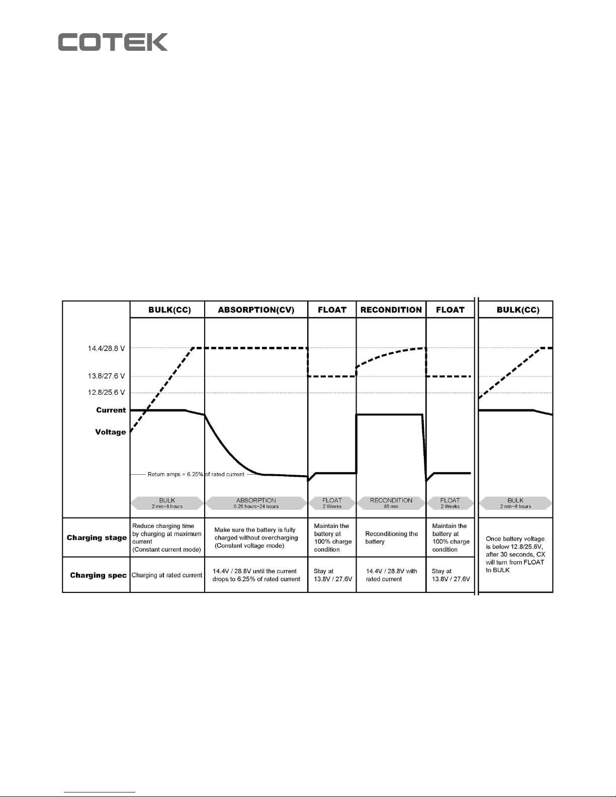
2-1-1 Bulk Stage (Constant Current)
At the beginning of the charging process, the flat battery is charged at constant current
(maximum charge current) until the battery voltage reaches the set charging voltage (Refer
to 3-2 charging mode setting).
Page 6

4
2-1-2 Absorption Stage (Constant Voltage)
The absorption charging duration will depend on the battery status.
Before moving to absorption stage, charger will wait for two minutes then charging at
constant voltage until the battery is fully charged.
Once the battery is fully charged or the charging current is below 6.25% of the rated
charging current for 15 minutes, then the absorption stage ends.
2-1-3 Float Stage
After absorption stage, the battery charger switches to float stage, maintains the battery at
100% charge without overcharging or damaging the battery. This means the charger can
be left connected to the battery continuously.
2-1-4 Recondition stage
Every 12 days, the battery charger switches back to Bulk stage for 85 minutes in order to
revive the battery. This prevents any fatigue symptoms such as sulphation.
Page 7
5
2-2 Specification
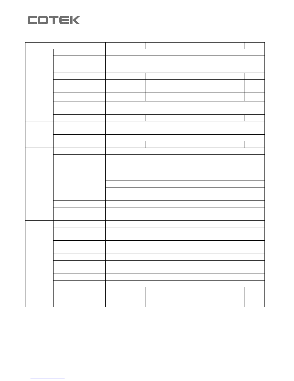
Model
CX1215
CX1225
CX1235
CX1250
CX1280
CX2415
CX2425
CX2440
Output
Battery Type
Lead Acid / Li-ion / Gel / AGM
Standard Boost Charge
Voltage
14.4V / 14.7V (Select by S1 DIP switch)
28.8V / 29.4V
(Select by S1 DIP switch )
Standard Float Charge
Voltage
13.8V / 13.5V (Select by S1 DIP switch)
27.6V / 27V
(Select by S1 DIP switch)
Main Rated Current
15A
25A
35A
50A
80A
12.5A
25A
40A
Main Output
1 2 2 3 3 2 3
3
ESB Output
1 1 1
--
--
--
--
--
ESB Output Voltage /
Current
13.8V/2A
13.8V/2A
13.8V/2A
--
--
--
--
--
Battery Charging Mode
3-stage charging capability IUOU
Isolation Type
Use active power MOSFET on each output terminal
Single Output Current Limit
15A
25A
35A
40A
40A
12.5A
25A
40A
Input
Voltage Range
90~264VAC
Frequency Range
47~63Hz
Power Factor (Typ.)
PF > 0.92 at full load
Efficiency (Typ.) at 230Vac
87%
87%
87%
87%
87%
90%
90%
90%
Protection
Short Circuit
Current is reduced to < 1A continued 30sec., will operate 30 seconds then turn off
Over Voltage
17.5V ±1%, protection type: shut down output
(recovery after resetting AC power ON)
35V ±1%, protection type: shut
down output
( recovery after resetting AC
power ON )
Over Temperature
Charger Over Temperature 100 ±5°C detected by heat sink
52±5°C (Optional temperature sensor)
Auto recovery after heat sink temperature goes down to 50±5°C
Function
Alarm Signal
NC. / NO. Relay contact output (Please reference Alarms signal & Fan control)
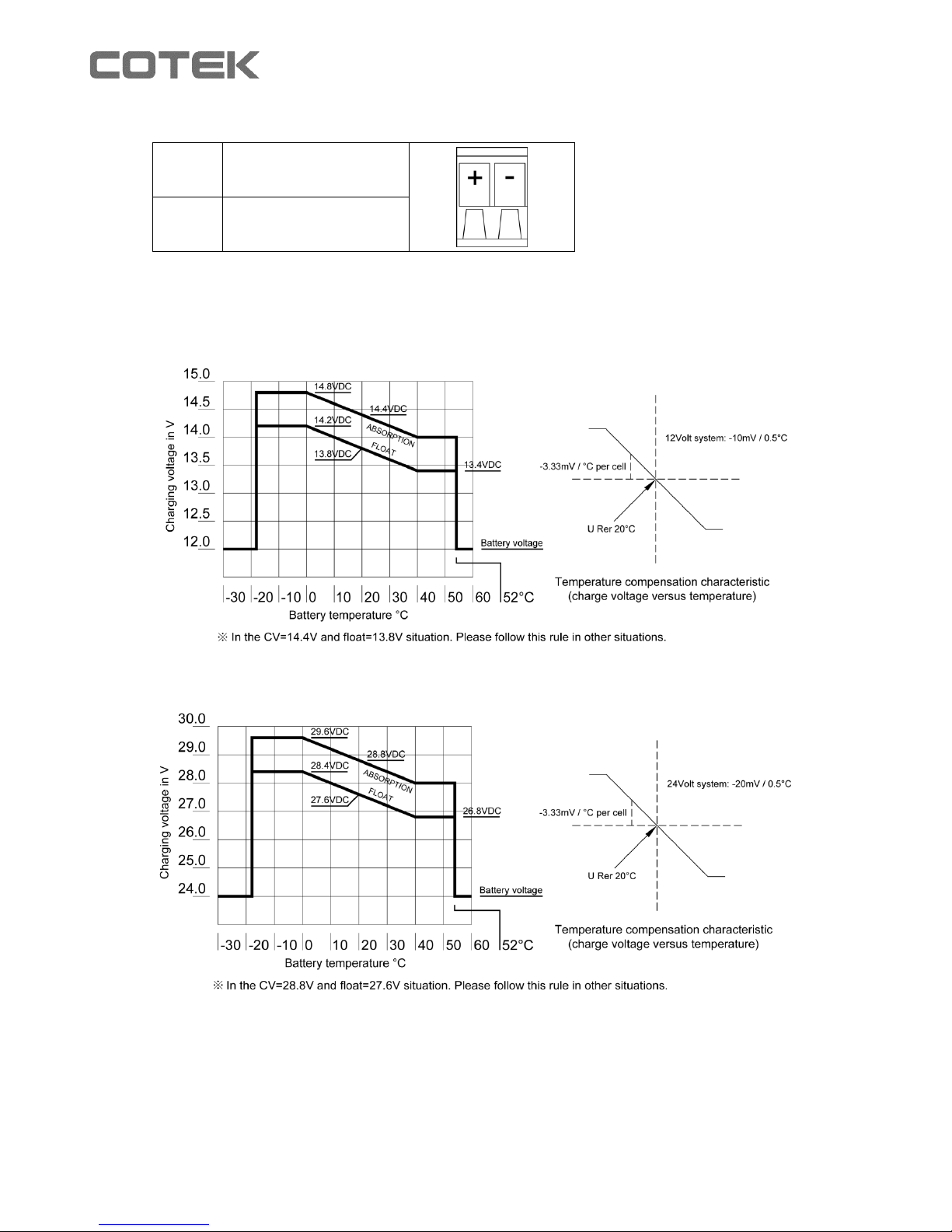
Temperature Compensation
-10mv / 0.5°C with COTEK temperature sensor
Sleep Mode
By Remote Controller and S1-4 DIP switch (Please refer to section 3-2)
Remote Controller
Support COTEK Remote Controller CR-1 ( Please refer to section 3-6 and 3-7)
Environment
Working Temp.
-20~50°C (refer to output load de-rating curve)
Working Humidity
20~90% RH non-condensing
Temp. Coefficient
±0.03% (0~50°C)
Vibration
10~500Hz, 2G 10min. / 1cycle period for 60min. each along X, Y, Z axes.
Safety
&
EMC
Safety Standards
Certified EN 60335-1, EN60335-2-29
Withstand Voltage
I/P-O/P: 4242VDC, I/P-FG: 1768VDC, O/P-FG: 700VDC
Isolation Resistance
I/P-O/P: 100M Ohms / 500VDC
EMI Conduction & Radiation
EN 55022; EN 55024; EN 61204-3; EN 55014-1; EN 55014-2
Harmonic Current
EN 61000-3-2; EN 61000-3-3; EN 61204-3; EN 61000-6-1; EN 61000-6-3
EMS Immunity
IEC 61000-4-2, 3, 4, 5, 6, 8, 11; ENV 50204
Others
Dimension (WxHxD)
(Unit: mm)
183x72x243.4
183x72
x263.4
213x76.5
x272.4
213x76.5
x312.4
183x72
x243.4
213x76.5
x272.4
213x76.5
x312.4
Packing (Unit: kg)
1.6
1.7
1.9
3.1
4.0
1.6
2.9
3.9
Page 8
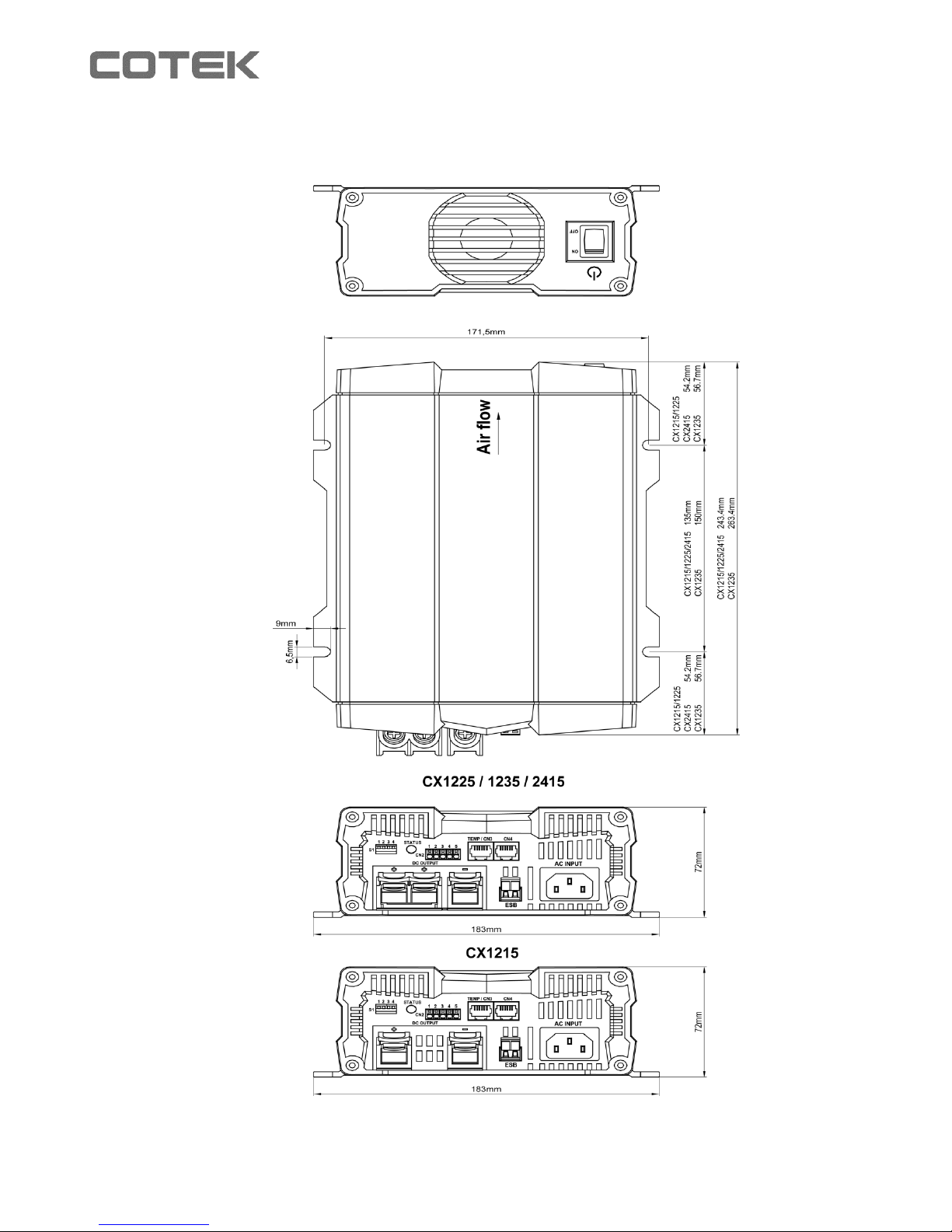
6
2-3 Mechanical Drawings
Model: CX1215/1225/1235/2415
Unit: mm
Page 9
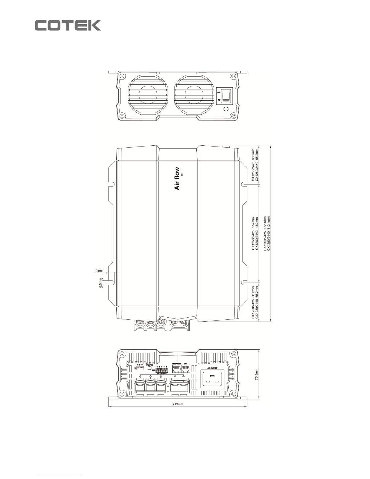
7
Model: CX1250/1280/2425/2440
Unit: mm
Page 10
8
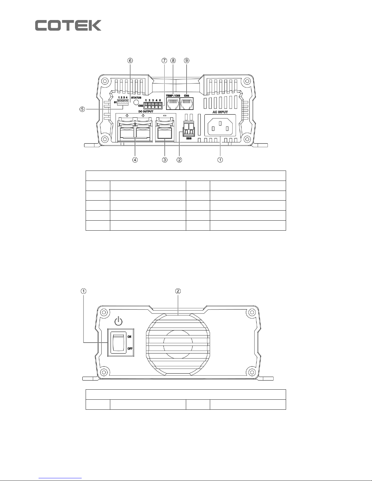
2-3-1 CX1215/1225/1235/2415 (Front Panel)
Front panel
①
AC Inlet (IEC)
⑥
Status LED
②
ESB connector
⑦
CN2
③
DC output -
⑧
TEMP/CN3
④
DC output +
⑨
CN4
⑤
Dip Switch 1 (S1)
Note: For detail description on item 5 (Dip Switch S1), please refer to section 3-2
2-3-2 CX1215/1225/1235/2415 (Rear Panel)
Rear panel
①
Power Switch
②
Fan
Page 11
9
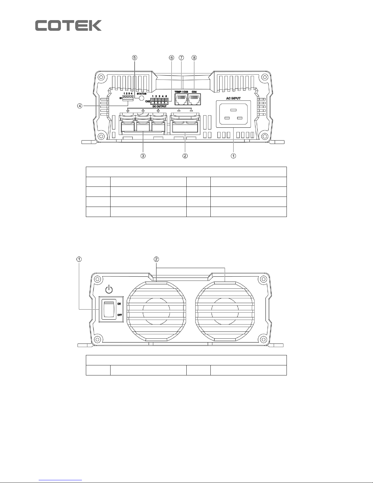
2-3-3 CX1250/1280/2425/2440 (Front Panel)
Front panel
①
AC Inlet (IEC)
⑤
Status LED
②
DC output -
⑥
CN2
③
DC output +
⑦
TEMP/CN3
④
Dip Switch 1 (S1)
⑧
CN4
Note: For detail description on item 4 (Dip Switch S1), please refer to section 3-2
2-3-4 CX1250/1280/2425/2440 (Rear Panel)
Rear panel
①
Power Switch
②
Fan
Page 12
10
3. Product Description
Below models are available with COTEK Advanced Battery Charger CX Series:
3-1 Configurations
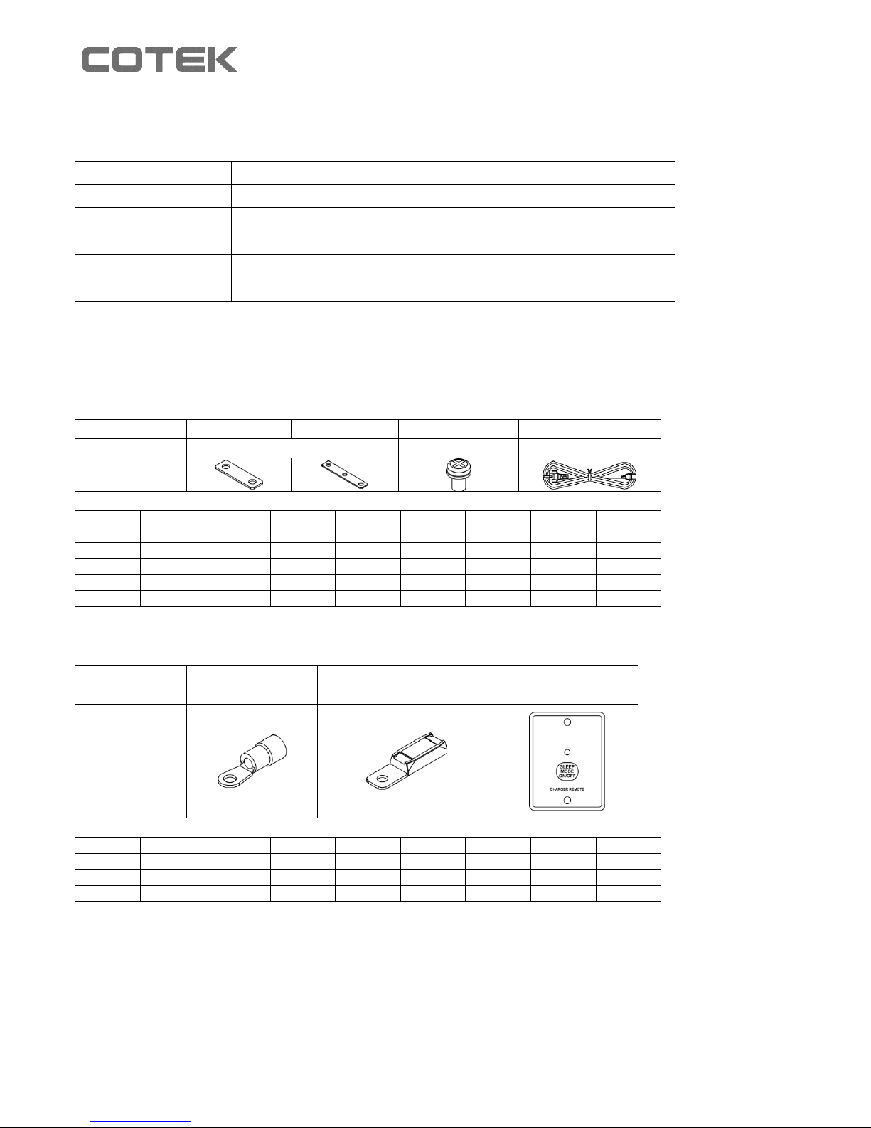
3-1-1 Standard Accessory
Number
A B C
D
Description
Copper Bus
Screw
AC Power Cable
Diagram
Quantity
per
CX1215
CX1225
CX1235
CX1250
CX1280
CX2415
CX2425
CX2440
A x 1pcs
1pcs x x
1pcs x x B x x x
1pcs
1pcs
x
1pcs
1pcs C x
2pcs
2pcs
3pcs
3pcs
2pcs
3pcs
3pcs
D
1pcs
1pcs
1pcs
1pcs
1pcs
1pcs
1pcs
1pcs
3-1-2 Optional Accessory
Number A B
C
Description
Ring Terminal
Battery Temp Sensor
Remote
Diagram
Number
CX1215
CX1225
CX1235
CX1250
CX1280
CX2415
CX2425
CX2440
A
2pcs
3pcs
3pcs
5pcs
5pcs
3pcs
5pcs
5pcs
B
1pcs
1pcs
1pcs
1pcs
1pcs
1pcs
1pcs
1pcs
C
1pcs
1pcs
1pcs
1pcs
1pcs
1pcs
1pcs
1pcs
Model
No. of supply battery
Support ESB (Engine Start battery)
CX1215
1
Yes
CX1225 /CX1235 2 Yes
CX1250 /CX1280 3 No
CX2415
2
No
CX2425 /CX2440 3 No
Page 13
11
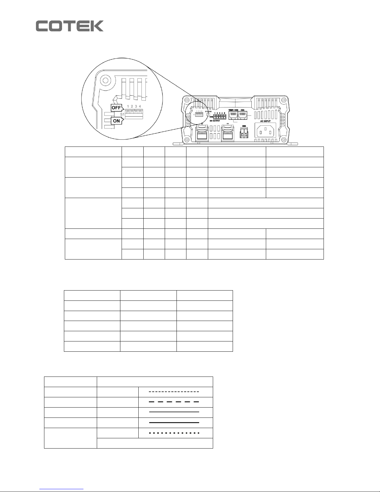
3-2 S1 Dip Switch Setting
Status
1 2 3 4 12V / 24V CC/CV
12V / 24V Float
CC turn to CV
voltage
ON X OFF X 14.4V / 28.8V
---
OFF
X
OFF X 14.7V / 29.4V
---
Float voltage
X
ON
OFF X ---
13.5V / 27.0V
X
OFF
OFF X ---
13.8V / 27.6V
Power Mode
(Current limit
output voltage)
OFF
OFF
ON
X
13.2V / 26.4V
OFF
ON
ON
X
13.8V / 27.6V
ON
OFF
ON
X
14.4V / 28.8V
Remote
ON
ON
ON X ---
---
Fan force ON/OFF
X X X
ON
---
---
X X X
OFF
---
---
X: Not Applicable
---: By Default setting
3-2-1 Default setting
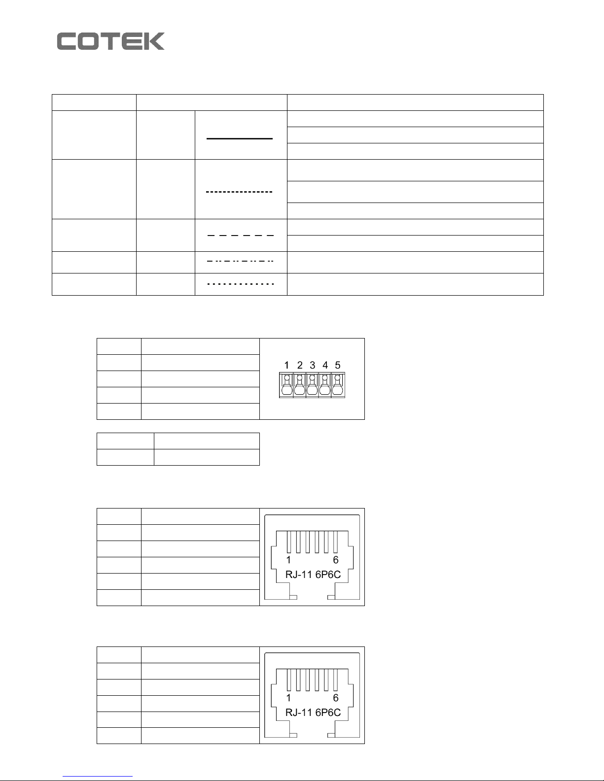
3-3 Charging Status LED Indicator
Charging status
LED Status
Bulk-1
Orange fast
Bulk-2
Orange slow
Absorption-1
Orange solid
Absorption-2
Green solid
Float
Green flash
LED color change by the status change
Model
12V Series
24V Series
CC/CV
14.4V
28.8V
Float
13.8V
27.6V
Power Mode
Off
Off
Remote
Off
Off
Fan
Full Speed
Full Speed
Page 14
12
3-4 Failure Indicator
Failure status
LED Status
Description
Input or Output
Red solid
Output current is reduced to <1A
AC I/P unstable
Output FUSE blown
Temperature
Red fast
Battery over heat (the indicator is available only when
COTEK temperature sensor is connected)
Battery under heat ( the indicator is available only when
COTEK temperature sensor is connected)
Charger over heat (Heat Sink)
Battery voltage
Red slow
Battery over voltage
Battery under voltage or output under voltage in C.C. mode.
Fan abnormality
Red light
flash twice
Fan abnormality
ESB Failure
Red light
slow ones
ESB no output / output short
3-5 Pin Assignment of CN2 – For Alarms Signal & Fan Control
1
Normally closed
2
Normally open
3
COM
4
Sleep mode control
5
GND
4-5 Short
Sleep mode on
4-5 Open
Sleep mode off
3-6 Pin Assignment of CN3 – For Temperature sensor & Remote control
1
R_VCC
2
GND
3
TEMP
4
BAT-
5
DATA I/O
6
BAT+
3-7 Pin Assignment of CN4 – For Remote control)
1
R_VCC
2
BAT-
3
NC.
4
BAT-
5
DATA I/O
6
BAT+
Page 15
13
3-8 Pin Assignment of ESB Connectors - For CX1215/1225/1235)
+
VCC
-
GND
3-9 Temperature Compensation
CX12xx Series model
CX24xx Series model
Page 16
14
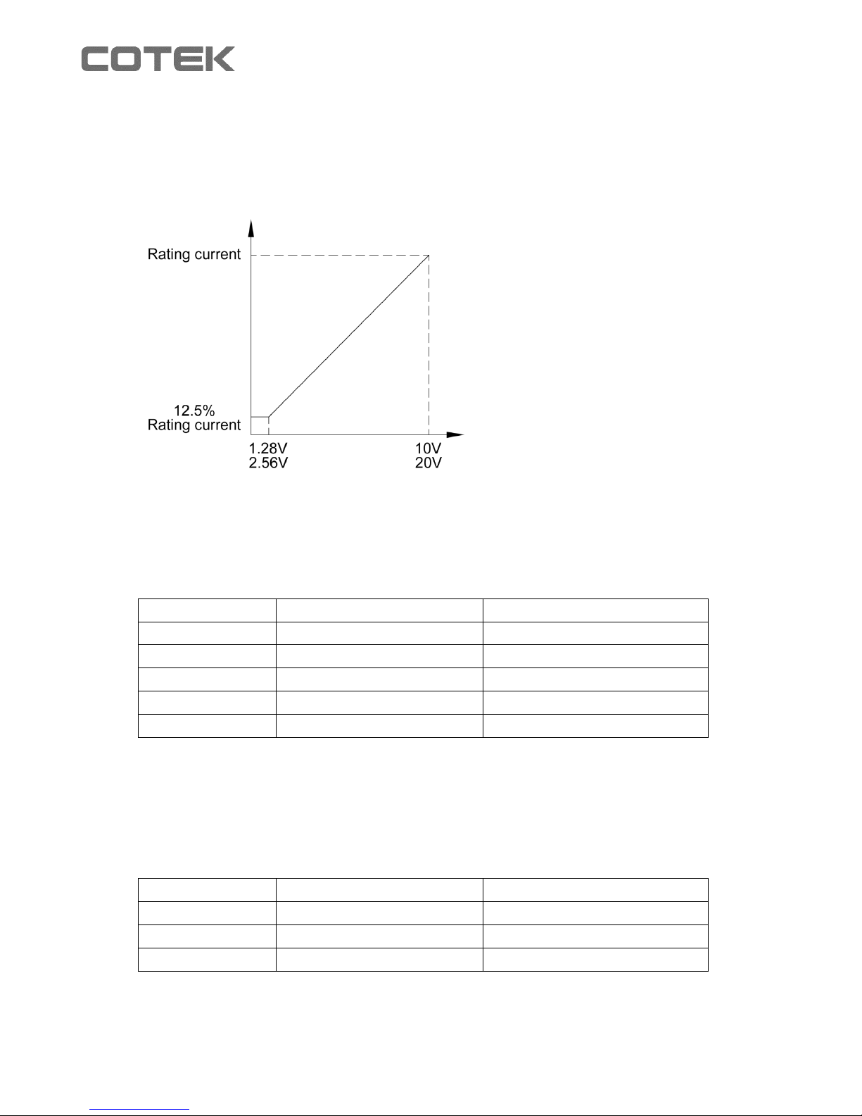
3-10 Rescue Battery Curve:
In case of battery over discharge (when battery voltage lower than 10V), CX battery
charger will reduce the charging current to prevent further damage on the battery.
The following curve is only applicable for Lead-acid & AGM battery.
3-11 Battery Charger Selection (Reference only)
12 Volt Battery
COTEK Model
Battery capacity range
Estimated charging time
CX1215
50~80Ah
6~24
CX1225
80~125Ah
6~24
CX1235
125~175Ah
6~24
CX1250
175~250Ah
6~24
CX1280
250~400Ah
6~24
The above suggested battery charger selection is based on battery capacity multiply
0.2~0.3. Example: 100Ah battery * 0.2 / 0.3 = 20A~30A in this case please select CX1225.
24 Volt Battery
COTEK Model
Battery capacity range
Estimated charging time
CX2415
50~80Ah
6~24
CX2425
80~125Ah
6~24
CX2440
125~200Ah
6~24
The above suggested battery charger selection is based on battery capacity multiply
0.2~0.3. Example: 100Ah battery * 0.2 / 0.3 = 20A~30A in this case please select CX2425.
Page 17

15
3-12 Battery Voltage setting suggestion
GEL TYPE (Max. Voltage of 14.1 / 28.2 Volt)
AGM TYPE (Max. Voltage of 14.4 / 28.8 Volt)
Lead-Acid (Max. Voltage of 14.8 / 29.6 Volt)
4. Installing the COTEK Advanced Charger
When selecting the installation location, observe the following instructions:
The battery charger can be installed horizontally or vertically.
Do not install the charger in following situations:
In wet environment
In dusty environment
In the vicinity of combustible materials
In areas where there is a danger of explosions
The place of installation must be well ventilated. A ventilation system must be
available for installation in small, enclosed space. The clearance around the device
must be at least 25cm.
The charger must be installed on a level and sufficiently sturdy surface.
Do not install the charger above batteries, because they can emit corrosive sulphur
fumes that will damage the device.
For ambient temperatures higher than 40 ℃ (such as in engine or heating
compartments, or direct sunlight), the heat from the charger under load can lead to
reduced output.
The air inlet on the underside and the air outlet on the back of charger must remain
clear.
Page 18
16
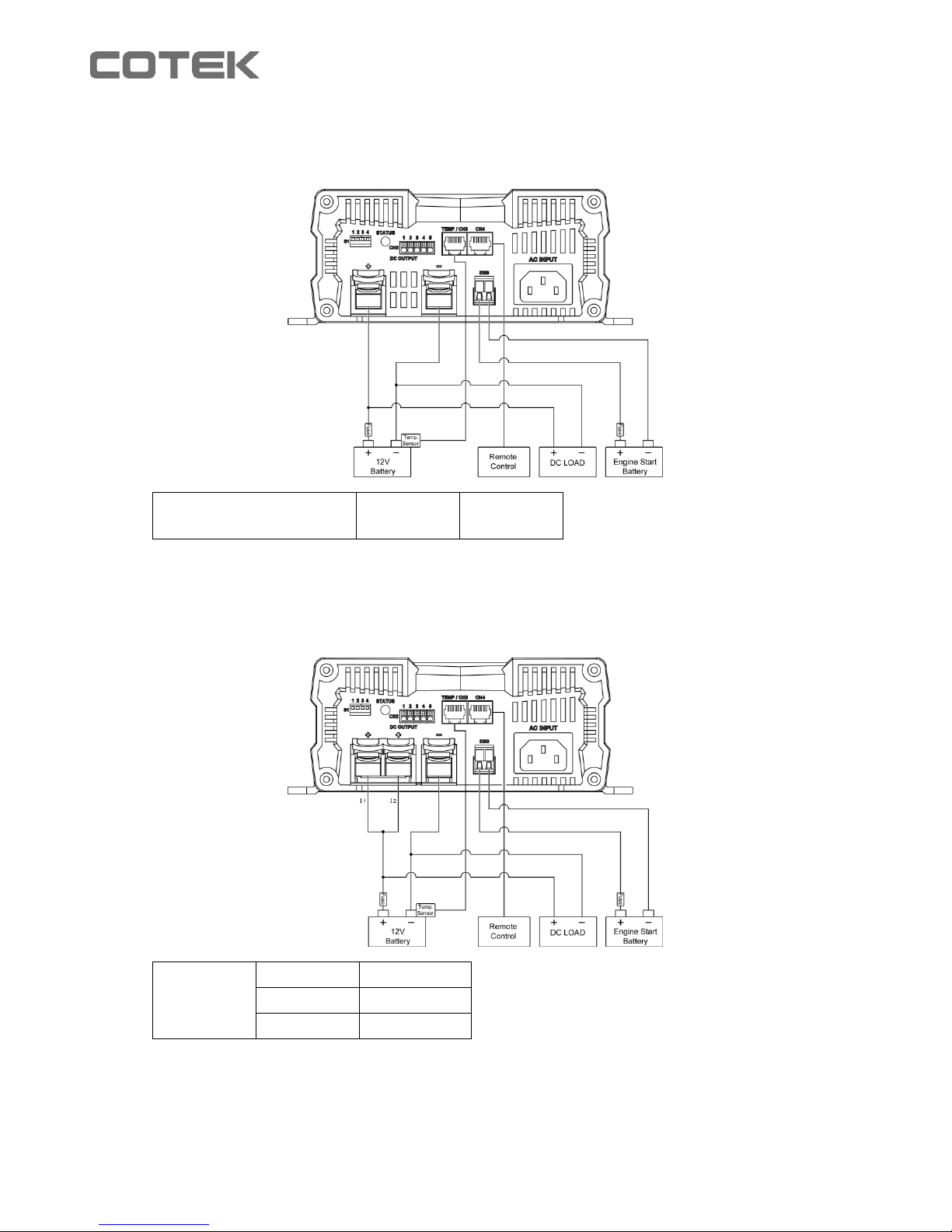
4-1 Battery charger connection diagram
Model: CX1215
Single output charging
CX1215
15A MAX
Model: CX1225/CX1235/2415
I1 + I2
CX-1225
25A MAX
CX-1235
35A MAX
CX-2415
12.5A MAX
Page 19
17
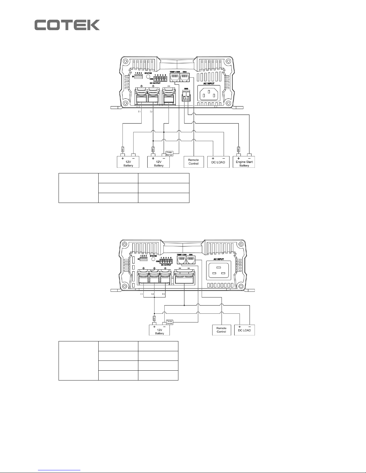
I1 or I2
CX-1225
25A MAX
CX-1235
35A MAX
CX-2415
12.5A MAX
Model: CX1250/CX1280/2425/2440
I1+I2+I3
CX-1250
50A MAX
CX-1280
80A MAX
CX-2425
25A MAX
CX-2440
40A MAX
Page 20
18
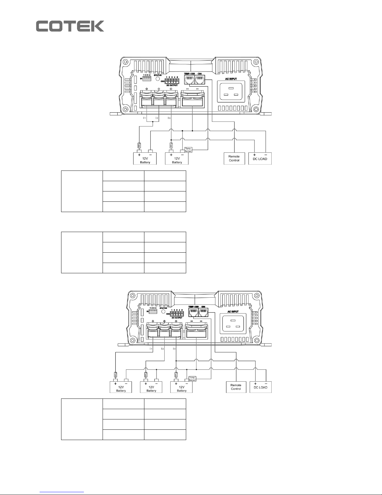
I1+I2
CX-1250
50A MAX
CX-1280
80A MAX
CX-2425
25A MAX
CX-2440
40A MAX
I3
Single
output
charging
CX-1250
40A MAX
CX-1280
40A MAX
CX-2425
25A MAX
CX-2440
40A MAX
Single
output
charging
CX-1250
40A MAX
CX-1280
40A MAX
CX-2425
25A MAX
CX-2440
40A MAX
Page 21
19
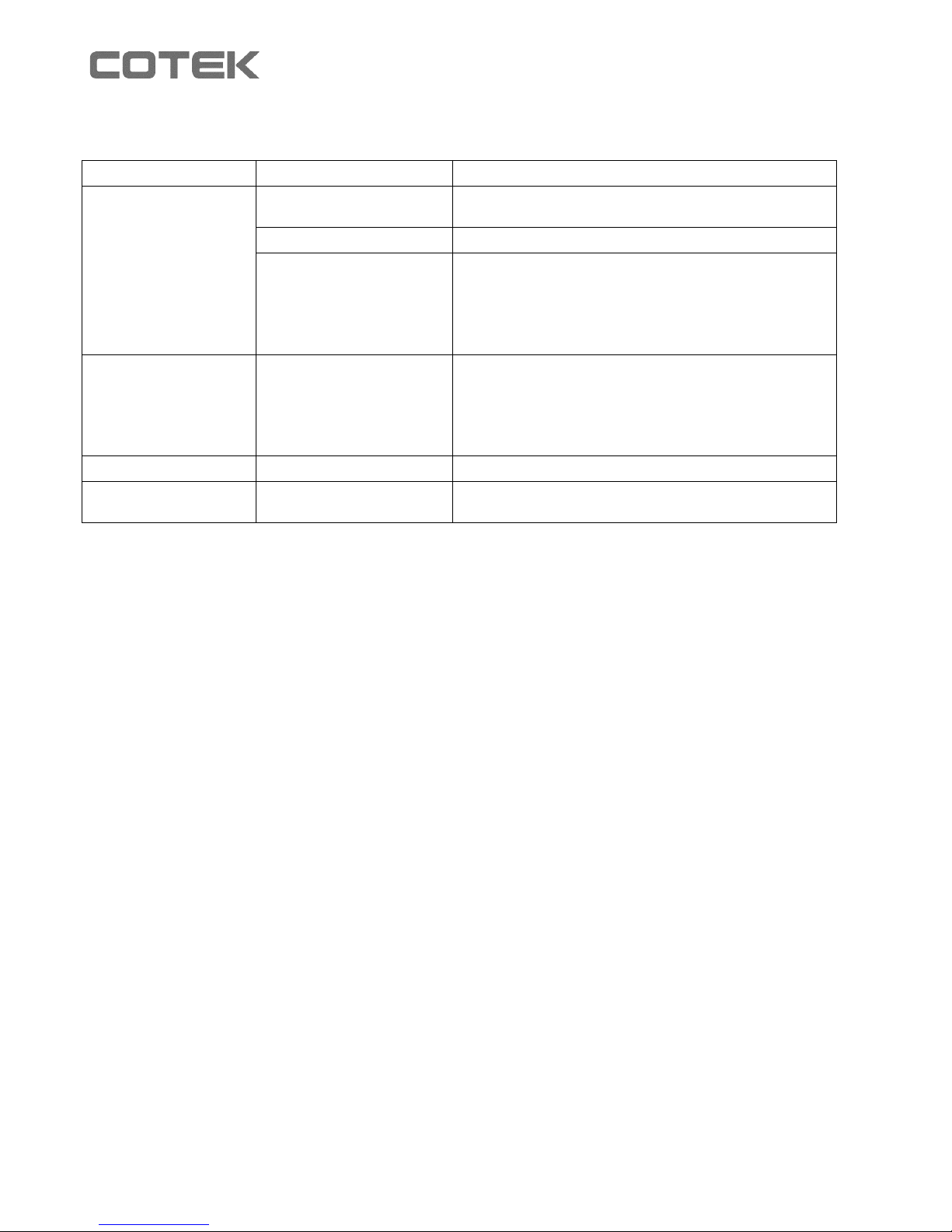
5. Trouble Shooting
LED display
Cause
Remedy
Red, slowly flashing
Battery under voltage
or battery overload
Check the battery.
Switch the battery charger off and on again.
Defective battery
Replace the battery
Overheating
Improve the ventilation of the battery charger
or battery.
Make sure that no ventilation openings are
covered.
If necessary, reduce the ambient temperature.
Red, permanently lit
Short circuit or
reversed polarity
Connect the battery charger with the correct
polarity.
Rectify the short circuit.
Check if the fuse has blown and replace it if
necessary.
Red, double flash
Fan fault
Check the fan for dirt or damage.
Red, slow double
flash
Fault at the starter
battery connection
Check the starter battery connection for a short
circuit.
6. Warranty Statement
We guarantee this product against defects in materials and workmanship for a period of 24 months
from the date of purchase. Please contact your local COTEK authorized distributor for RMA
(Return material Authorization) service. Please note that COTEK is only responsible for ensuring
our products are operational before delivery. This warranty will be considered void if the unit has
been misused, altered, or accidentally damaged. COTEK is not liable for anything that occurs as a
result of the user’s fault.
Page 22

No. 33, Sec. 2, Renhe Rd., Daxi Township, Taoyuan County 33548, Taiwan
Phone:+886-3-3891999 FAX:+886-3-3802333
http:// www.cotek.com.tw
Update: 2014.07
 Loading...