

Page 1
1.User’s Guide For CR8 Remote Controller
1-1. Features::
Remote ON/OFF inverter operation
Ignition lockout information display and Return Override Function Acting
1-2. Specification:
Input Voltage Range: 10.5 – 60 Vdc depends on Inverter model.
Operating Temperature Range : 0 – 40 ℃
Storage Temperature Range : - 30 ℃ - 70 ℃
Stand-By Current Draw : < 40mA
Applicable Models : ST / SK / SD / SE series
1-3. Introduction::
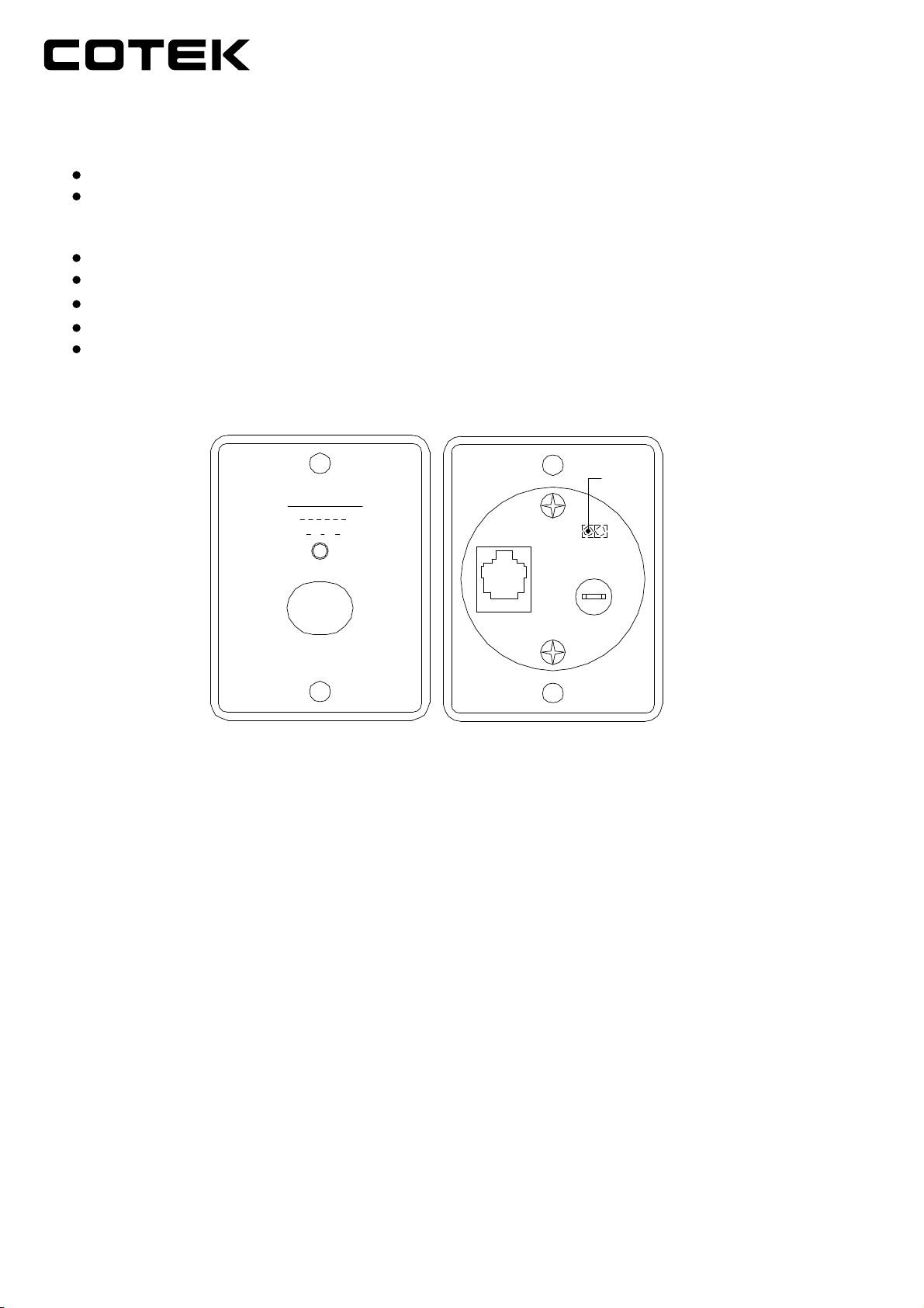
(INTERNAL)
PIN
Inverter Status
Solid Red
Blinking Fast
Blinking Slow
Inverting
R.O.F Acting
Ignition
TO
INVERTER
JUMPER
AUX. +12V
PUSH
ON/OFF
INVERTER REMOTE
● This is a simple ON / OFF remote control.
* Steady red LED light in dicates the Inverter is ON.
* Fast flashing red LED light indicates that it is in Return Override Function selection status.
* Slow flashing red LED light indicates that it is in Ignition Lockout Function selection status.
● The wire JP1 is placed inside the remote controller and it is to indicate either Return Override
Function or Ignition Lockout Function.
* JP1 jumper “Open” – Return Override Function
* JP1 jumper “Short” – Ignition Lockout Function
Please note that the default mode is OPEN.
● The wire must go with a 12 Volt 0.5A fuse with proper sizes.
● Connect the wire RJ-11 to the remote port in front of the panel.
* Ignition Lockout function – The Ignition lockout function is to turn the Inverter OFF when
the auxiliary input wiring is connected to the ACC. (accessory), and 12 Volts is applied.
* Return Override Function – The Return Override Function is to turn the Inverter ON when
the auxiliary input wiring is connected to the reverse gear Shift, and 12 Volts is applied.
● Installation Procedure:
1. Refer to the drawing (see Figure 1) for screw hole and cutout dimensions.
2.Use the cable between CR8 remote and the inverter.
3.Switch the inverter to REMO position.
Page 2
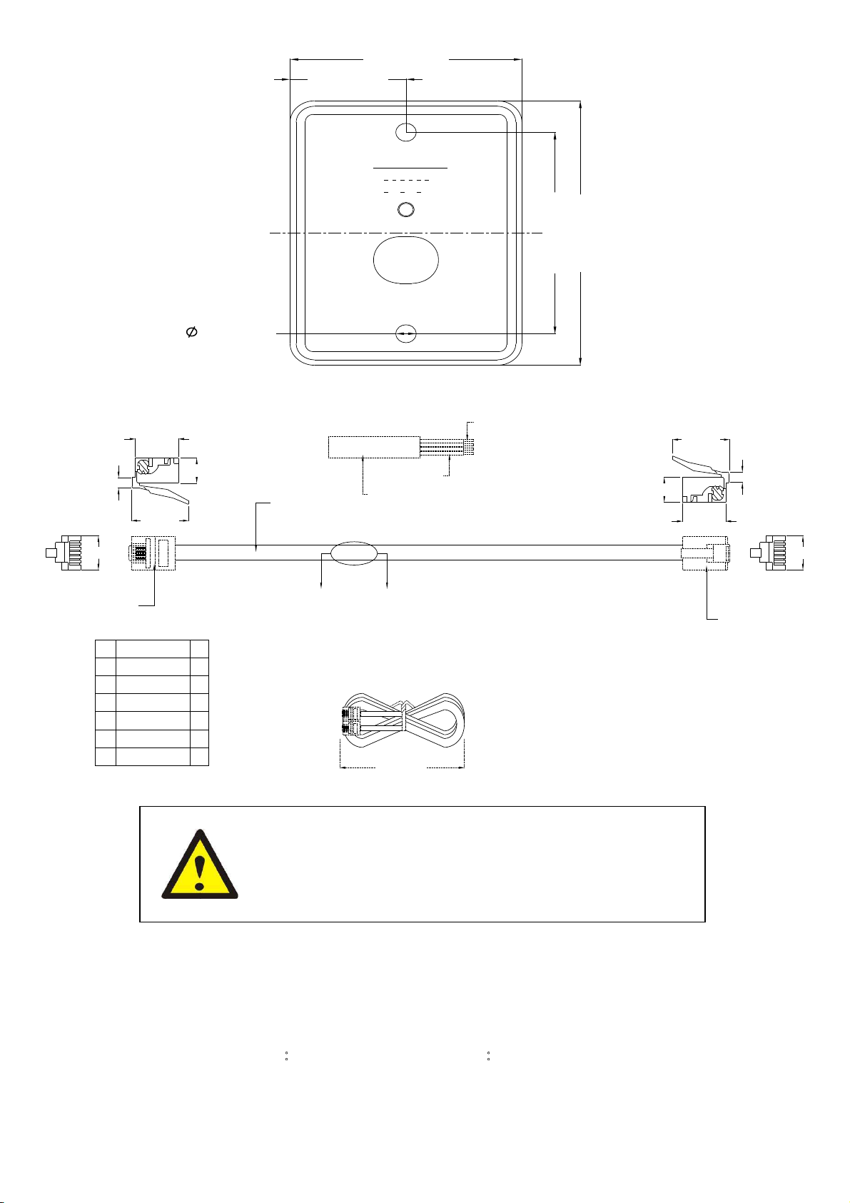
57.0 [2.24]
28.5 [1.12]
Inve rter S tatu s
So lid R ed
Blink in g Fa st
Blink in g Slo w
Invertin g
R. O.F Ac tin g
Ignition L oc ko ut
PU SH
ON/OF F
IN V E RT E R R E M O TE
56.0 [2.20]
73.5 [2.89]
5.00 [0.20]
Figure 1
1-4. Drawings of CR-8 Remote Control Cables
CONDUCTOR
12.4±0.3
3.1±0.2
A B
6
9.6±0.2
1
(2)
6.5±0.2
(1)
14.6±0.3
A
INSULATION
JACKET
CABLE STRUCTURE (A-A)
A
A BCOLOR
6 6NC
5 5YELLOW
4 4GREEN
3 3RED
2 2BLACK
1 1NC
160±10mm
14.6±0.3
6.5±0.2
12.4±0.3
3.1±0.2
6
9.6±0.2
1
(2)
WARNING!
DO NOT use standard telephone cable.
No.33, Sec. 2, Renhe Rd., Daxi Dist., Taoyuan City 33548, Taiwan
Phone:+886-3-3891999 FAX:+886-3-3802333
2016.01 A1
 Loading...