

Page 1
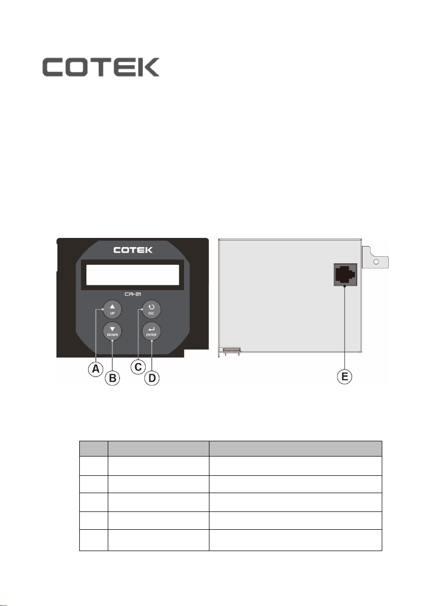
Description
Function
A
UP
Scroll up
B
DOWN
Scroll down
C
ESC
Go back to previous page.
D
ENTER
Enter next page and save setting value
E
RJ-45 port
Connect to the Inverter
Front and rear Panel introduction
User Guide For CR-21 PLUS Remote Control
1. Introduction
1-1. System
The remote is designed to easily and quickly connect Cotek SR-1600 Plus.
The LCD display is used for setting up the inverter, as well as displaying current
status or fault messages. Pressing buttons allows you to select a menu item or
to save a setting, once it is displayed on the LCD screen.
Page 2
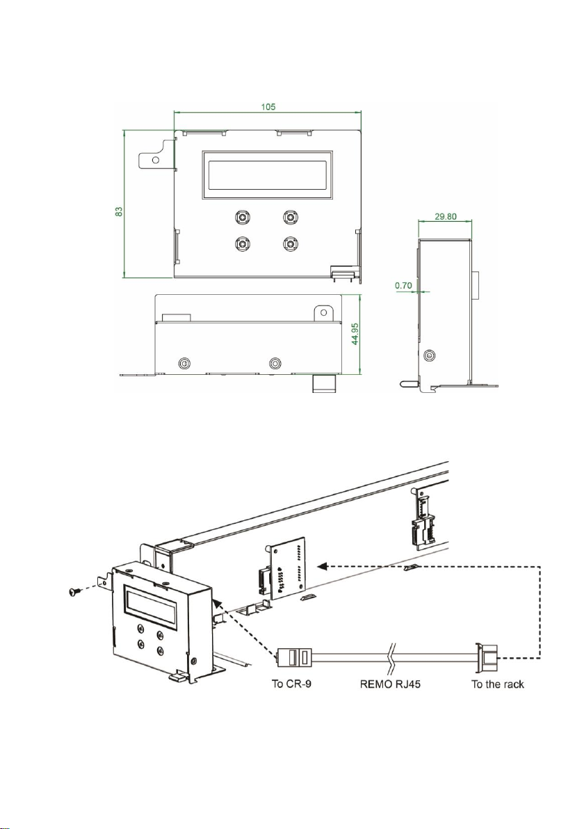
1-2. Mechanical Drawings
Unit: mm
1-3. Hardware Installation
Page 3
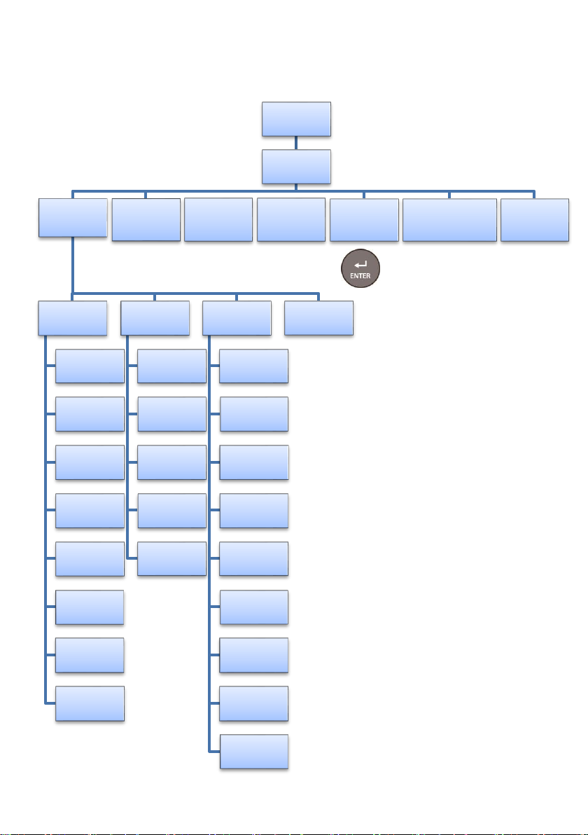
2. Display tree
Enter into System Setup by “press for 3 seconds”
GRID-->SR-->LOAD
BAT-------^ Major
2-1
User Interface
2-3
LCD Contrast
2-3-1
LCD Auto-off
2-3-2
Baudrate
2-3-3
DRY C Setting
2-3-4
Alarm Setting
2-3-5
OUTPUT:
xxx.xV
xx.xHz xxx.xA
Bat Parameter
2-4
OVP Setting
2-4-1
OVP Recovery
2-4-2
UVP Setting
2-4-3
UVP Recovery
2-4-4
UV Alarm
2-4-5
OUTPUT
xxW xxVA
AC Parameter
2-5
O/P Voltage
O/P Frequency
Sync Frequency
AC or DC Mode
AC Sharing
2-5-1
2-5-2
2-5-3
2-5-4
2-5-5
Power Switch
ON
INVERTER
Initialization..
OUTPUT
xxW% xxVA%
Display Event
2-6
GRID:xxx.xV
xx.xHz xxx.xA
BATTERY:xxx.xV
discharging xxx.xA
STATUS:
2-2
DateTime Setting
2-3-6
Password Setting
2-3-7
Output On/Off
2-3-8
AC OVP Setting
2-5-6
AC OVP Recovery
2-5-7
AC UVP Setting
2-5-8
AC UVP Recovery
2-5-9
Page 4
2-1 GRID-->SR-->LOAD BAT-------^ Major
STATIS
Possible Cause
Normal
The machine is working normally
Machine Abnormal
Parallel Fault or Module Fault
Grid Abnormal
AC source abnormal
Fan Fault
Fan does not work
BAT. Low
Under DC voltage protevtion
BAT. High
Over DC voltage protection
Over Load
The system over the rated capacity(OLA >15sec)
Redundancy Fault
Remove the redundancy module or redundant module failure
Over Temperature
Temperature is too high
BAT. Low Alarm
Under DC voltage Alarm
BAT. High Alarm
Over DC voltage Alarm
Over Load Alarm
The system over the rated apacity(OLA )
Major Relay On
Pin 12~13 voltage keep high(485 board)
Minor Relay On
Pin 14~13 voltage keep high(485 board)
Remote OFF
Turn off the machine from dry contact pin1& pin2
Setting Menu
SETT<value>
LCD Contrast
0 ~ 100
Setting Menu
SETT<value>
LCD Auto-off
0 ~ 120
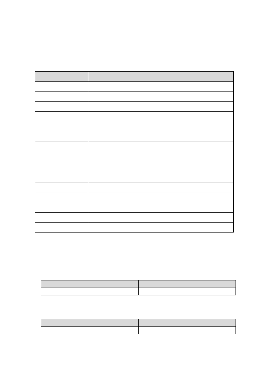
The connection status and Alarm type. For the description of alarm type, (Major /
Minor Alarm) please refer to Alarm List in the “SR-1600 Plus User Manual.”
2-2 STATUS:
2-3 User Interface
※The first time use the setting interface, must enter password (000000).
2-3-1 LCD contrast : Sets the LCD screen contrast.
Default = 50% Setting range = 0% ~ 100%
2-3-2 LCD Auto-off : Sets the LCD screen backlight auto off timer
Default = 120 seconds Setting range = 0 ~ 120 seconds
Page 5
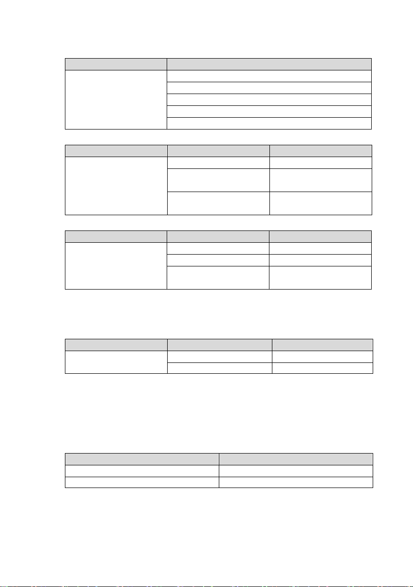
2-3-3 Baud rate : Default setting:4800
Setting Menu
SETT<value>
RS-485
Baud rate
1200
2400
4800
9600
19200
Setting Menu
SETT <value>
Description
Dry C setting
Disable
Disable
DRY C for Major
Selectable extra alarm to
go with Major
DRY C for Minor
Selectable extra alarm to
go with Minor alarm
Setting Menu
SETT <value>
Description
Alarm Setting
Normal
Normal
Mute
Mute all alarms
One time
Silent warning for current
status
Setting Menu
SETT <value>
Description
Output On/Off
On
Turn on the output
Off
Turn off the output
Model
Setting value range
24V
30 VDC ~ 34 VDC
48V
60 VDC ~ 68 VDC
2-3-4 Dry contact C setting : Default =1, Setting range = 0~2, default=1.
2-3-5 Alarm Setting: Default =1
2-3-6 Date Time Setting: Date yyyy-mm-dd Time hh-mm-ss
YY :year MM :month DD :date HH :hour MM :minute SS :second
2-3-7 Password Setting: 000000~999999, default setting:000000
2-3-8 Output On/Off:
2-4 Bat Parameter
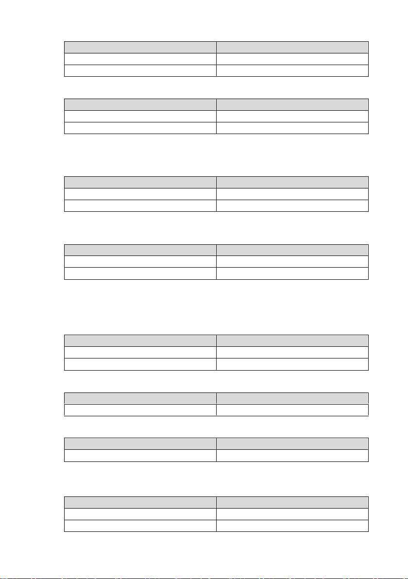
2-4-1 OVP Setting : Set the Over Voltage Protection (OVP) and shutdown.
Default = 34 VDC @ 24V Model. 68 VDC @ 48V Model
2-4-2 OVP Recovery : When the DC input voltage is higher than the OVP
setting, the SR series shuts down; once the input voltage falls below the set OVP
value, the SR series will automatically restart.
Default = 28 VDC @ 24V Model. 56 VDC @ 48V Model
Page 6
Model
Setting value range
24V
26 VDC ~ 30 VDC
48V
52 VDC ~ 60 VDC
2-4-3 UVP Setting : Setting Under Voltage Protection (UVP) and shutdown on
Model
Setting value range
24V
18 VDC ~ 25 VDC
48V
36 VDC ~ 50 VDC
Model
Setting value range
24V
23 VDC ~ 27 VDC
48V
46 VDC ~ 54 VDC
Model
Setting value range
24V
19 VDC ~ 26 VDC
48V
38 VDC ~ 52 VDC
Model
Setting value range
1XX
97 VAC ~ 127 VAC
2XX
194 VAC ~ 254 VAC
Model
Setting value range
1XX & 2XX
50 or 60 Hz
Model
Setting value range
1XX & 2XX
0 Hz ~ 3 Hz
Mode Priority
SETT<value>
DC Mode
0
AC Mode
1
the inverter operation. Default= 18 VDC @ 24V Model. 36VDC @ 48V Model
2-4-4 UVP Recovery : When the DC input voltage is below the set UVP value,
the SR series shuts down; once the input voltage rises above the set UVP
value, the SR series will automatically restart.
Default= 25 VDC @ 24V Model. 50VDC @ 48V Model
2-4-5 UV Alarm : Setting Under Voltage (UV) alarm. When the input voltage is
lower than the set value, the SR series will sound a “beep” to remind you that the unit
is going to shutdown. Default= 21 VDC @ 24 V Model. 42 VDC @ 48 V Model
2-5 AC Parameter
2-5-1 O/P Voltage : Setting the SR series output voltage on the inverter
operation. 1xx = 100V, 110V, 115V or 120V ; 2xx = 200V, 220V, 230V or 240V.
2-5-2 O/P Frequency : Setting the SR series output frequency on the inverter
operation. 1xx = 100V, 110V, 115V or 120V ; 2xx = 200V, 220V, 230V or 240V.
2-5-3 Sync Frequency : Setting SR series output frequency tolerance range on the
inverter operation. 1xx = 100V, 110V, 115V, 120V ; 2xx = 200V, 220V, 230V or 240V.
2-5-4 AC or DC Mode : Default =1, AC Mode is the 1st priority source.
DC Mode:DC is the 1st priority source, and the AC power is the 2nd priority source.
AC Mode:AC is the 1st priority source, and the DC power is the 2nd priority source.
Page 7
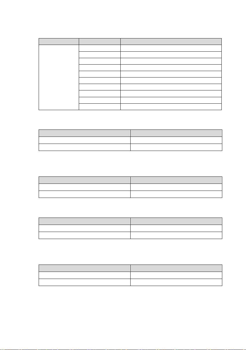
2-5-5 AC Sharing : Setting range = 10, 20, 30, 40, 50, 60, 70, 80, 90, 100
Setting Menu
SETT<value>
Description
AC Ratio
10
AC load 10%, DC load 90%
20
AC load 20%, DC load 80%
30
AC load 30%, DC load 70%
40
AC load 40%, DC load 60%
50
AC load 50%, DC load 50%
60
AC load 60%, DC load 40%
70
AC load 70%, DC load 30%
80
AC load 80%, DC load 20%
90
AC load 90%, DC load 10%
100
Disable
Model
Setting value range
1xx
127.5 VAC ~ 132.5 VAC
2xx
255 VAC ~ 260 VAC
Model
Setting value range
1xx
120 VAC ~ 127 VAC
2xx
240 VAC ~254 VAC
Model
Setting value range
1xx
75 VAC ~ 90 VAC
2xx
150 VAC ~ 180 VAC
Model
Setting value range
1xx
90.5 VAC ~ 100 VAC
2xx
181 VAC ~ 200 VAC
Default= 100 (Disable)
2-5-6 AC OVP Setting : Set the Grid Over Voltage Protection (OVP) and transfer
to DC mode(or shuts down without battery).
Default = 130 VAC @ 1xx Model. 260 VAC @ 2xx Model
2-5-7 AC OVP Recovery : When the AC input voltage is higher than the OVP
setting, the SR series transfer to DC mode(or shuts down without battery); once the
input voltage falls below the set AC OVP recovery value, the SR series will
re-operate in AC mode. Default = 125 VAC @ 1xx Model. 150 VAC @ 2xx Model
2-5-8 AC UVP Setting : Set the Grid Under Voltage Protection (UVP) and transfer
to DC mode(or shuts down without battery).
Default= 90 VAC @ 1xx Model. 180VAC @ 2xx Model
2-5-9 AC UVP Recovery : When the AC input voltage is below the set UVP value, the
SR series transfer to DC mode(or shuts down without battery) ; once the input voltage rises
above the set UVP recovery value, the SR series will re-operate in AC mode.
Default= 95 VAC @ 1xx Model. 190VAC @ 2xx Model
Page 8
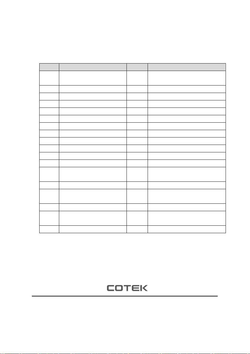
2-6 Display Event
Model
Setting value range
Model
Setting value range
002
Output off
020
Under DC voltage protection
recovery
003
Output on
021
Under DC voltage protection
004
AC share off
022
Overload alarm recovery
005
AC share on
023
Overload alarm
006
AC mode off
024
Overload protection recovery
007
AC mode on
025
Overload protection
008
DC mode off
026
Fan normal
009
DC mode on
027
Fan failure
010
Grid Volt normal
028
Over temperature protection recovery
011
Grid Volt abnormal
029
Over temperature protection
012
Freq normal
030
The Machine was working
013
Freq abnormal
031
Component failed
014
Over DC voltage alarm
recovery
032
IC Power voltage normal
015
Over DC voltage alarm
033
IC Power voltage abnormal
016
Over DC voltage protection
recovery
034
Insert the module
017
Over DC voltage protection
035
Remove the module
018
Under DC voltage alarm
recovery
036
Redundancy _OK
019
Under DC voltage alarm
037
Redundancy_lost
Error code list
2-6-1Display description
XXX (index) code:XXX (please refer to Error code List)
YY-MMDD-HH-MM-SS (Event time)
※Enter the event page the first information is the latest event
No.33, Sec. 2, Renhe Rd., DaxiDist., Taoyuan City 33548, Taiwan
Phone:+886-3-3891999 FAX:+886-3-3802333
http:// www.cotek.com.tw
2019.03._A0
 Loading...