

Page 1
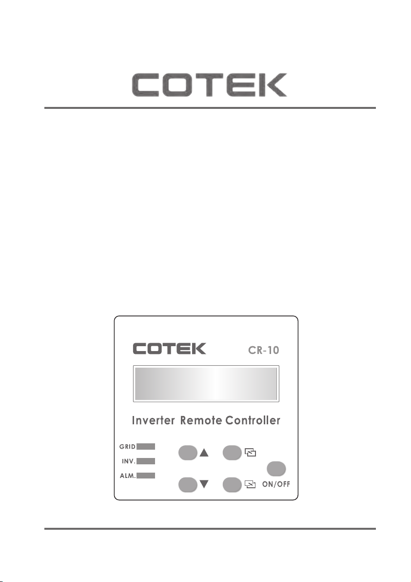
CR-10
Remote Control
User’s Manual
www.cotek.com.tw
Page 2
Remote control introduction
Press the ON / OFF button on the front. The SD-series starts working
normally. After switching on expect a five to ten second delay.
The SD-series will be operating in normal condition when either of the
following messages are displayed on the LCD panel screen :
92
80
46
92
2-φ3.3
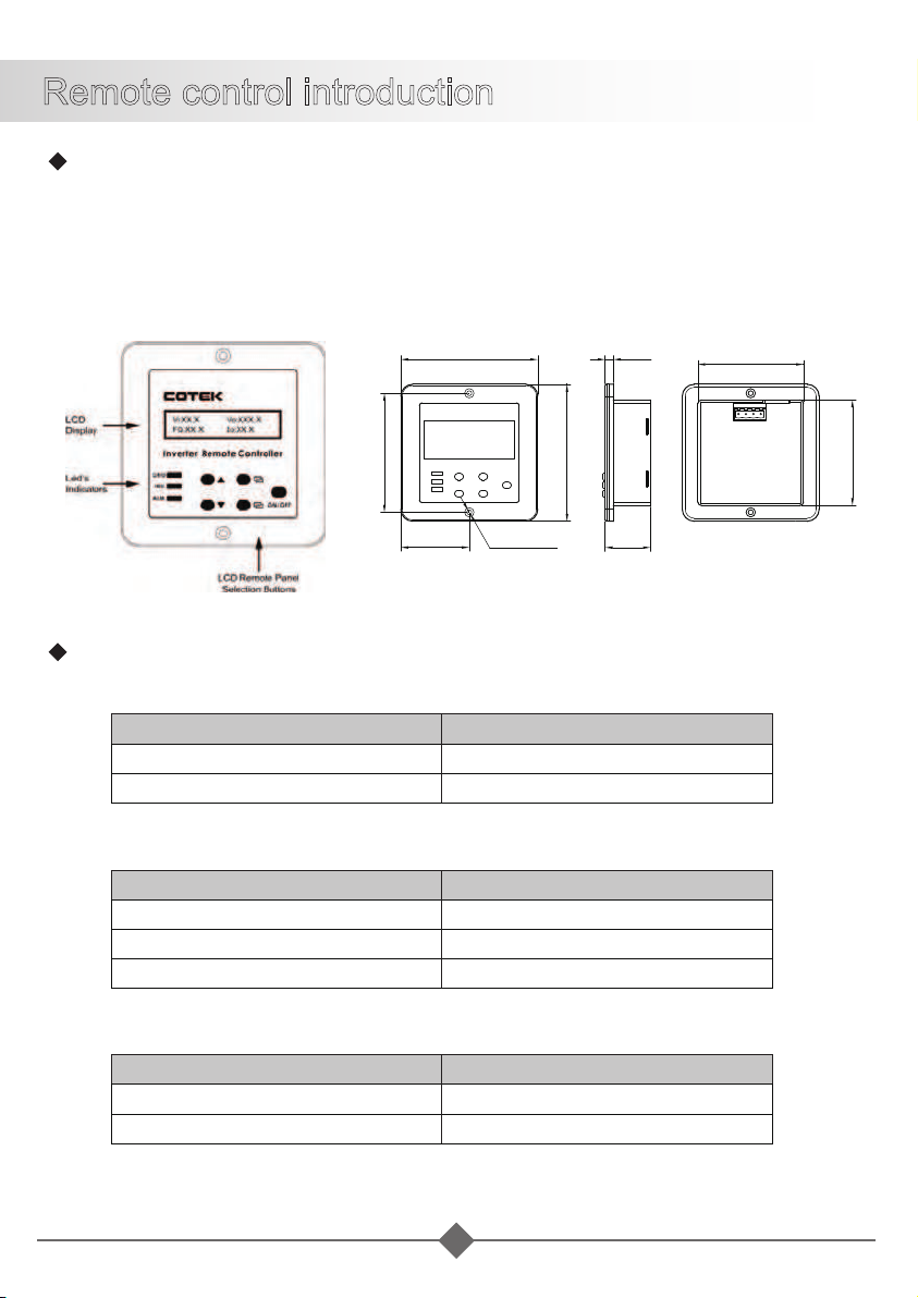
LED Indications :
˙
GRID: Displays incoming AC input status.
AC Input
AC input ON
AC input OFF
˙
Inverter: Displays the SD-series working statuses.
DC-AC Inverter LED Status
Inverter AC Working
Inverter AC Saving
Inverter AC shunt down
LED Status
Green
OFF
Green
Green Blink
OFF
30.5
5.5
71
71
˙
Alarm: Displays the SD-series alarm status.
Alarm LED Status
Abnormal
Normal
1
Red
OFF
Page 3
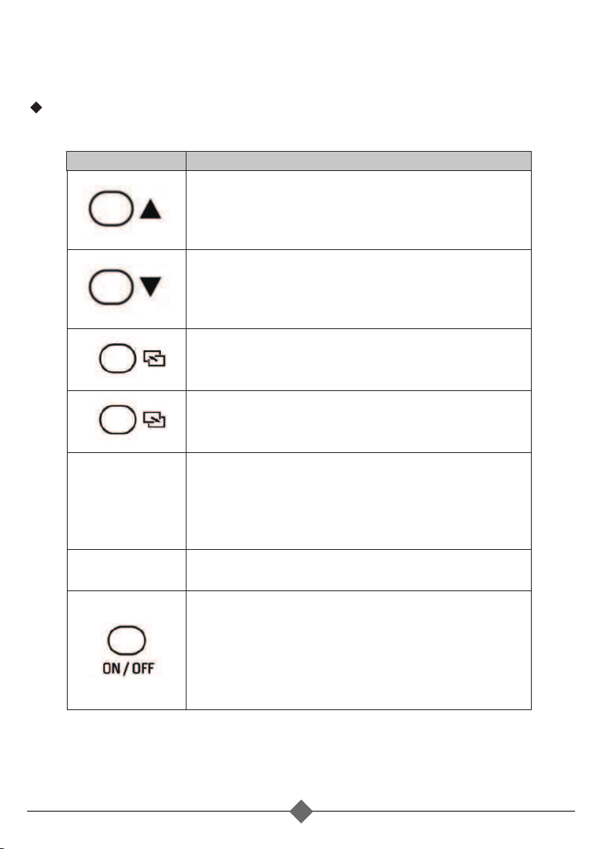
LCD Remote Control Panel Selection Buttons :
˙
Function :
Function
[Up]
You can use the “up” button to scroll through
the menus or to select the value for set up
under setting mode.
[Down]
You can use the “Down” button to scroll through
the menus or to select the value for set up
under setting mode.
[Page Up]
You can use the “Page Up” button to scroll
through the menus.
[Page Down]
You can use the “Page Down” button to scroll
through the menus.
[Enter Setup Menu]
Press the button longer than 3 seconds, The
SD-series will change to “Select Menu” which
appears on the LCD screen for the user to set
functions.
[Enter]
Confirms a selection or value.
[ON / OFF]
The SD-series can be activated by the button.
Press “ON / OFF” button, the SD-series to
startup. If you want to turn OFF the SD-series,
press the “ON / OFF” button longer than 3
seconds.
2
Page 4
LCD Rear View Introduction
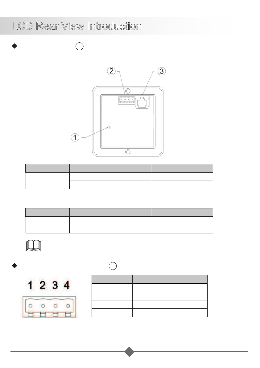
Jump (reference 1 )
The “J1 jump” is placed inside the remote controller.
˙
J1 jump “open”
J1 Jump “CTL” Input Voltage
Open
˙
J1 jump “short”
J1 Jump “CTL” Input Voltage
Short
5 ~ 60 VDC
0 V
5 ~ 60 VDC
0 V
Note: The “J1” jump default mode is “short”.
Green Terminal (reference 2 )
PIN Function
1 ALM
2
3
4 -VCC
SD-series
Turn ON
Turn OFF
SD-series
Turn OFF
Turn OFF
CTL
-ENB
3
Page 5
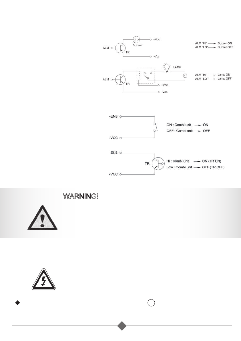
˙
ALM (PIN1)
When the SD-series
has the warning or the
protection displayed,
simultaneously this
“ALM” pin will changing
output to 5 Volt / 10mA
control signal to provide
the user.
˙
ENB (PIN3)
User can USE this
“-ENB” pin to control the
SD-series to turn ON or
turn OFF.
WARNING!
To turn “ON” the SD-series by operating the –ENB
function of LCD Panel, the SD-series inverter cannot
be turned OFF by any other operations, only by the
MAIN “OFF” SWITCH.
˙
-Vcc (PIN4)
This is LCD remote control panel ground.
ALM-Battery is common ground.
RJ-45 port, connect to inverter(reference 3 )
4
Page 6
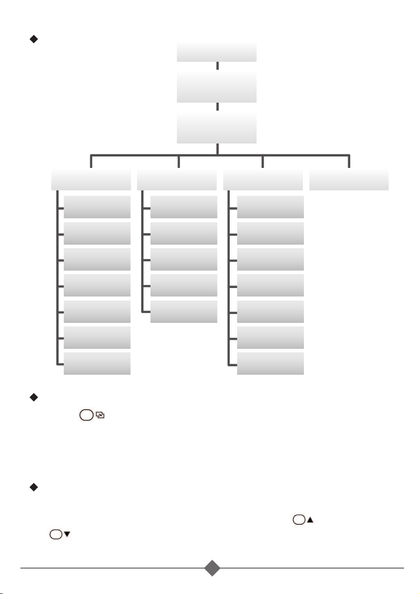
Display tree:
Power Switch ON
INVERTER
Initialization..
Vi=xx.xxVo=xxx.x
FQ=xx.x Io=xx.x
User Interface
LCD Contrast
<Function 14>
LCD Auto-off
<Function 15>
RS232 Baudrate
<Function 6>
Buzzer Setting
<Function 16>
Alert Setting
<Function 17>
Shut-down retry
<Function 10>
Language
<Function 18>
I/P Parameter
OVP Setting
<Function 0>
OVP Recovery
<Function 1>
UVP Setting
<Function 2>
UVP Recovery
<Function 3>
UV Alarm
<Function 4>
O/P Parameter
O/P Voltage
<Function 5>
O/P Frequency
<Function 7>
Sync Frequency
<Function 8>
Overload Alarm
<Function 9>
Saving Level
<Function 11>
Saving Interval
<Function 12>
Bypass Relay
<Function 13>
RST to Default
Operation and Instructions Entering Setup Menu:
Press button longer than 3 seconds. The SD-series enters the
select Menus consisting of four layers:
(1) User Interface: (2)I/P Parameter :
(3) O/P Parameter: (4)RST to Default:
Select Menu Heading:
The manual is used to show the status of the running SD-series.
The user can make selections by switching on <UP> or
<DOWN>.
5
Page 7
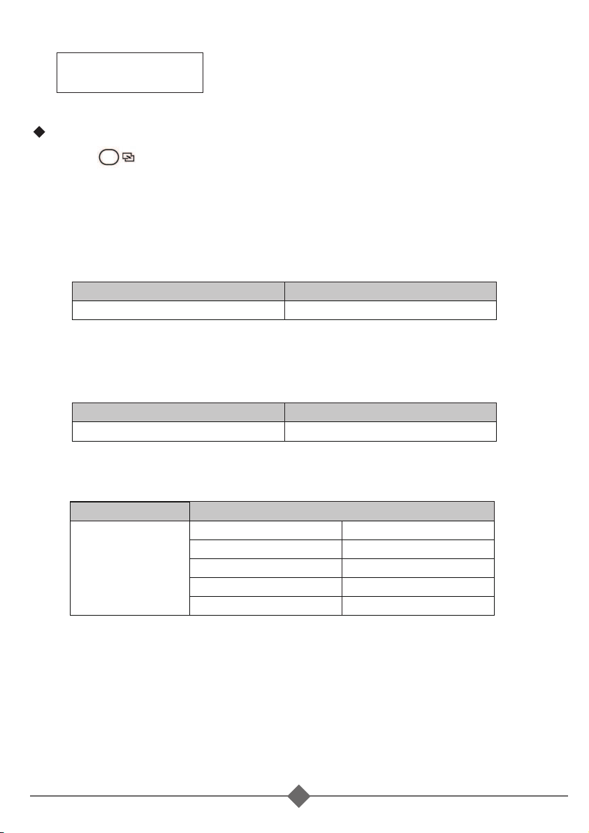
FQ = xx.x →Display the INV frequency.
Vi:XX.X
FQ:XX.X Io:XX.X
Vo:XXX.X
Io = xx.x →Display the INV output current.
FQ = xx.x →Display the INV frequency.
Io = xx.x →Display the INV output current.
Parameter Setting:
Press button before entering the “User Interface” menus.
˙
User Interface
1. LCD contrast : Sets the LCD screen contrast.
Default = 50%
Setting range = 0% ~ 100%
Setting Menu
LCD Contrast 0 ~ 100
SETT<value>
2. LCD Auto-off : Sets the LCD screen backlight auto off timer.
Default = 120 seconds
Setting range = 0 ~ 120 seconds.
Setting Menu
LCD Auto-off 0 ~ 120
SETT<value>
3. RS-232 Baud rate :
Default setting: 4800
0
1
2
3
4
SETT<value>
1200
2400
4800
9600
19200
Setting Menu
RS-232
Baud rate
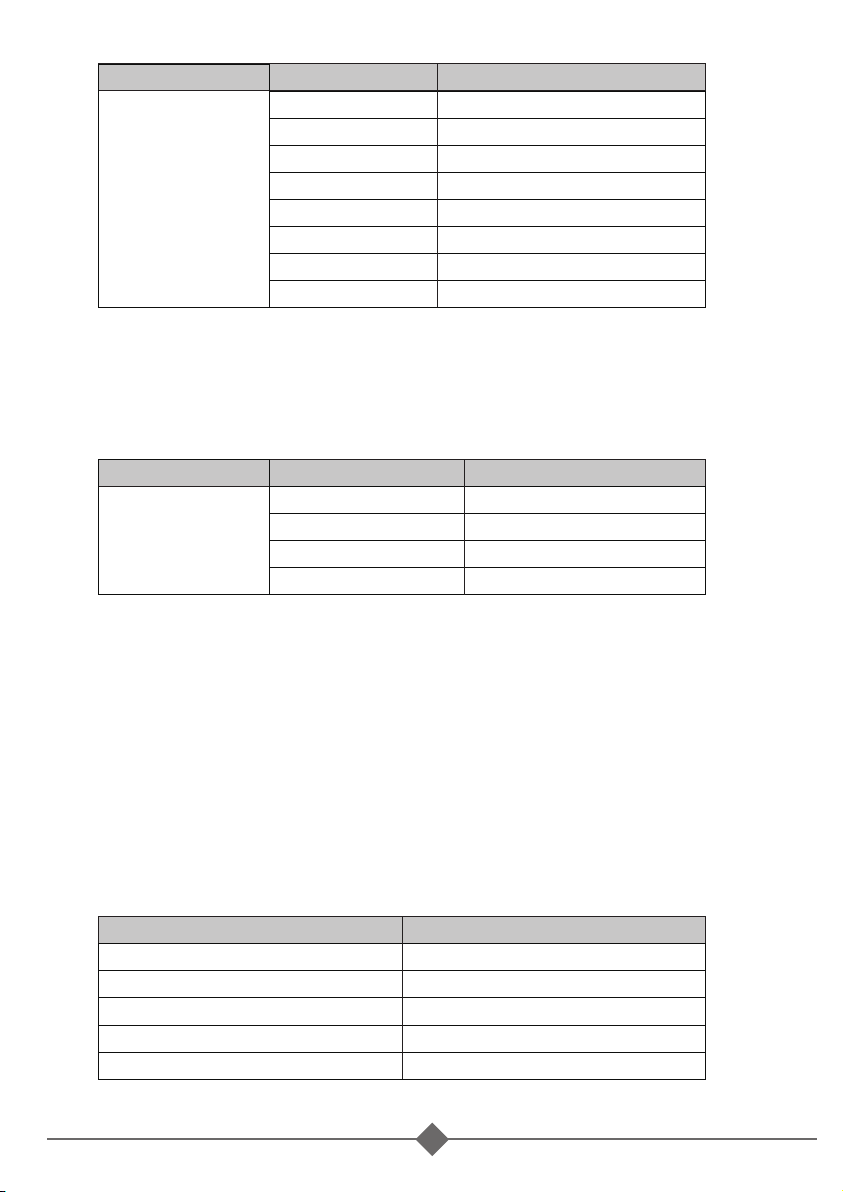
4. Buzzer setting : Set the LCD remote control for the buzzer sound
Default = MSG, Alert, SHDN
Setting range = 0~7
6
Page 8
Setting Menu
Buzzer
Setting
SETT(RS-232) Buzzer(Beep sound)
0
1
2
3
4
5
6
7
MSG , Alert , SHDN
Disable
SHDN
Alert
Alert , SHDN
MSG
MSG , SHDN
MSG , Alert
5. Alert Setting : When alert occurs, the internal dry contact relay
will open/close.
Default = Alert, SHDN
Setting range = 0~3
Setting Menu
RS-232
Baud rate
SETT (RS-232) Alert (LCD)
0
1
2
3
Disable
SHDN
Alert
Alert , SHDN
6. Shut-down retry : When SD-series is shut-down under OVP, UVP,
Overload or short circuit conditions, the inverter will automatically
try to restart according to the setting value.
Default = 5
Setting range: 0 ~ 15
7. Language : The SD-series have different languages available and
are selectable.
Default = English
Setting: English / Italian / Spanish / French / German
Model
English
Italian
Spanish
French
German
SETT (RS-232)
0
1
2
3
4
7
Page 9
˙
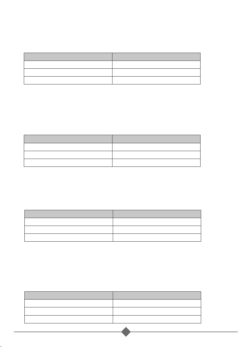
I/P Parameter
1. OVP Setting : Set the Over Voltage Protection (OVP) and shutdown.
Default = 16 VDC @ 12V Model, 32 VDC @ 24V Model.
64 VDC @ 48V Model
Model
12V
24V
48V
Setting value range
15 VDC ~ 16 VDC
30 VDC ~ 32 VDC
60 VDC ~ 64 VDC
2. OVP Recovery : When the DC input voltage is higher than the OVP
setting, the SD-series shuts-down; once the input voltage falls below
the set OVP value, the SD-series will automatically restart.
Default = 15 VDC @ 12V Model, 30 VDC @ 24V Model.
60 VDC @ 48V Model
Model
12V
24V
48V
Setting value range
13 VDC ~ 15 VDC
26 VDC ~ 30 VDC
52 VDC ~ 60 VDC
3. UVP Setting : Setting Under Voltage Protection (UVP) and
Shut-down on the inverter operation.
Default= 10 VDC@ 12V Model, 20 VDC @ 24V Model.
40VDC @ 48V Model
Model
12V
24V
48V
Setting value range
10 VDC ~ 11 VDC
20 VDC ~ 22 VDC
40 VDC ~ 44 VDC
4. UVP Recovery : When the DC input voltage is below the set UVP
value, the SD-series shuts-down; Once the input voltage rises above
the set UVP value, the SD-series will automatically restart.
Default= 12.5VDC @ 12V Model, 25 VDC @ 24V Model.
50VDC @ 48V Model
Model
12V
24V
48V
Setting value range
11.5 VDC ~ 13.5 VDC
23 VDC ~ 27 VDC
46 VDC ~ 54 VDC
8
Page 10
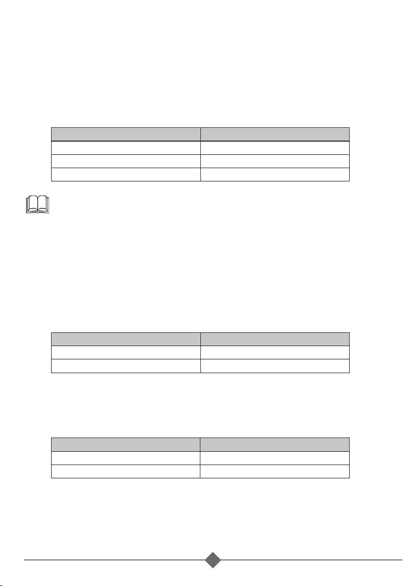
5. UV Alarm : Setting Under Voltage (UV) alarm. When the input
voltage is lower than the set value, the SD-series will sound a
“beep” to remind you that the unit is going to shut-down. In the
meantime, the contact in the internal Dry Contact Relay will
open / close.
Default= 10.5 VDC @ 12 V Model, 21 VDC @ 24 V Model.
42 VDC @ 48 V Model
Model
12V
24V
48V
Setting value range
10.5 VDC ~ 11.5 VDC
21 VDC ~ 23 VDC
42 VDC ~ 46 VDC
NOTE:
The value of the voltage set for the “UV Alarm” should be
equal to or higher than the value set for “UVP” or else the
unit will shut-down without any audible warning.
˙
O/P Parameter
1. O/P Voltage : Setting the SD-series output voltage on the
inverter operation.
Default= 110 VAC @110 V Model, 230 VAC @ 230 V Model
Model
110V
230V
Setting value range
97 VAC ~ 123 VAC
194 VAC ~ 246 VAC
2. O/P Frequency : Setting the SD-series output frequency on the
inverter operation.
Default= 60 Hz @ 110 V Model, 50 Hz @ 230 V Model.
Model
110V
230V
Setting value range
47 Hz ~ 63 Hz
47 Hz ~ 63 Hz
3. Sync Frequency : If a generator is distorted. The output
waveform (too low frequency) is used as AC source, the allowed
frequency window for the incoming AC power can be enlarged.
9
Page 11
Example1: AC input = 230 VAC / 50Hz, User setting Value= 7Hz
When the SD-series “Output frequency” is within The
Range of 43 Hz~57 Hz, the internal transfer relay will
close. When the output frequency is less than 43 Hz
or more than 57 Hz, the internal transfer relay will still
open.
Example2: When user setting value= Disable, the SD-series
“Output frequency” is within the range of 47 Hz~63 Hz,
the internal transfer relay will close.
Default= 7Hz
4. Overload Alarm : Set the overload alarm. When the SD-series
output power is higher than the set value, the SD-series will sound
a “beep” to remind you that the unit is going to shut-down. At the
same time, the internal Dry Contact Relay will open/close.
Default= 102%
Setting range= 50%~110%
5. Saving Level : Setting the SD-series to power saving to reduce
consumption from the batteries.
Default = 0
Setting range = 0 ~ 7
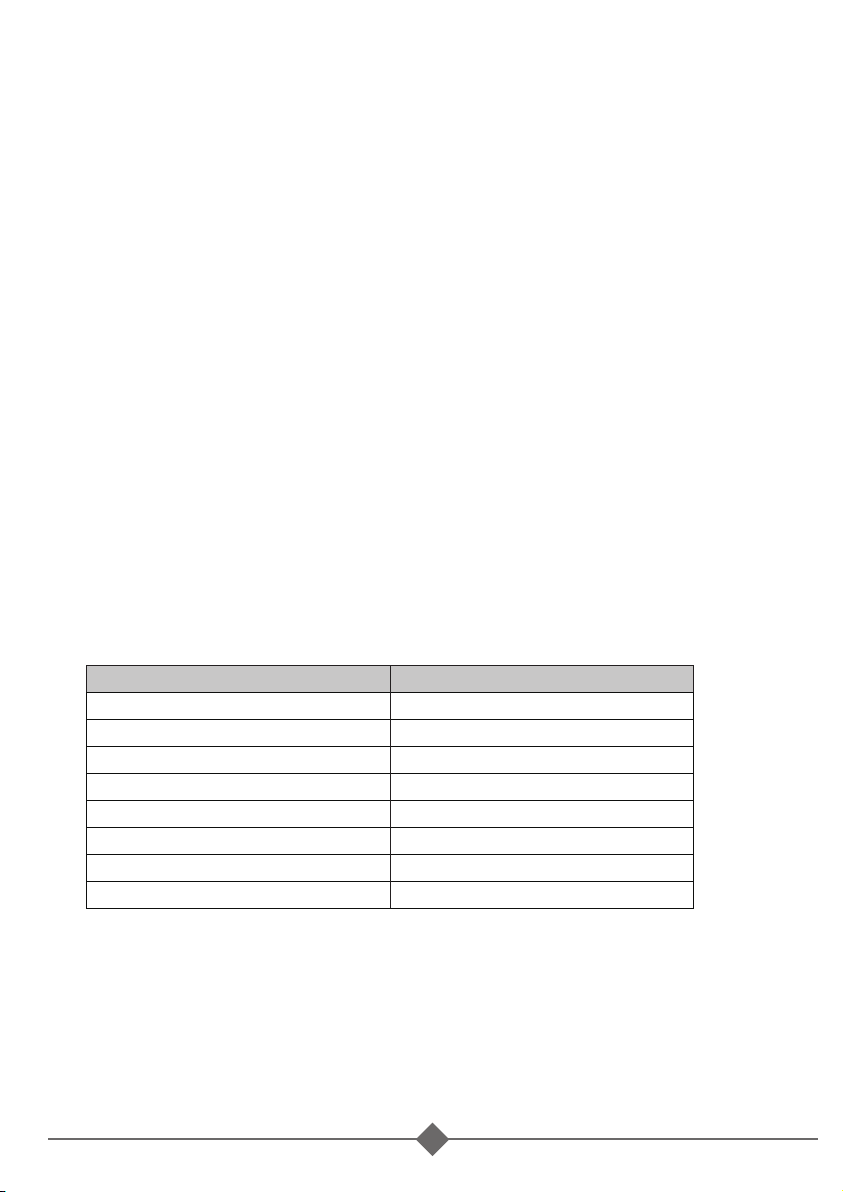
Setting Value
0
1
2
3
4
5
6
7
Status
Default
2%
3%
4%
5%
6%
7%
8%
6. Saving Interval : When SD-series inverter enters power saving
mode, it will detect AC Load periodically.
Default = 2.0 Seconds
Setting range = 1.0S ~ 2.0S
If the AC Load is 3 times higher than Saving Level, inverter will
recover and output normally to AC Load.
10
Page 12
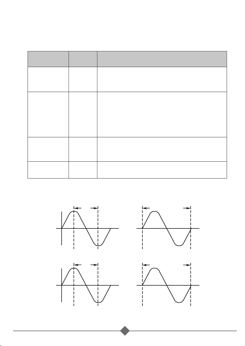
7. Bypass Relay : The setup is provided in one of the following two
ways.
On-line Mode or Off-line Mode ( Exacting, Normal, Haphazard).
Default= Normal (Off line).
Model
Haphazard 0
Normal
Exacting
On-line
SETT
<value>
Frequency
Synchronous
Setting value range
The transfer relay will switch “ON” or “OFF”.
Conformance to, phase and frequency
synchronization will not be considered.
The transfer relay will be “ON” if AC input (Grid)
power is available. The DC-AC inverter will
1
2
3
remain synchronized and Phase with the
incoming AC power (Grid). The relay will NOT
switch off if the grid frequency is beyond the
range set under Sync Frequency window.
The transfer relay will switch “ON” or “OFF”
based on conformance to, the Phase and Sync
Frequency.
Always supplied by battery until which has run
down (UVP) then switch to grid.
Phase
Synchronous
F
Phase
DC-AC Inverter DC-AC Inverter
F
AC input (GRID) AC input (GRID)
11
Phase
 Loading...