

Page 1
COSTER
D 610 - IPG 318 C2 Eng. 23.10.09 REV. 01
TWIN PUMP SWITCH
BUS
C
IPG 318 C2
• Adapts an On-Off signal to control twin pumps
• Automatically alternates operation of the two pumps
• In the event of lockout of the pump in operation, automatically switches on the other
• Two selectable C-Bus communication speeds, 1200 or 9600 baud
• 230 V ~ power supply, DIN rail mounting
1. APPLICATION
Used to adapt an On-Off signal to control and automatically manage twin pumps..
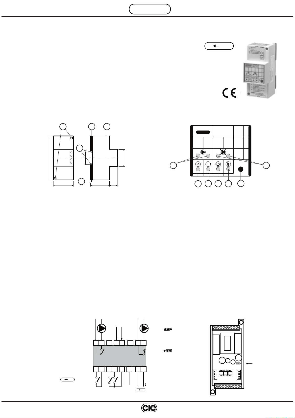
2. OVERALL DIMENSIONS 3. FRONT PANEL
D 610
23.10.09 AM
REV.01
3
2
1
4
115
53
1 – Protective cover for electronic components
2 – Base with transformer, relay and terminal blocks
3 – Cover-base fastening screws
4 – DIN rail securing elements
5 – DIN rail release lever
35
5
50,5 21
45
4. TECHNICAL DATA
Power supply 230 V ~ ± 10%
Frequency 50 ÷ 60 Hz
Consumption 3 VA
Protection IP40
Radio disturbances VDE0875/0871
Vibration test 2g (DIN 40 046)
Voltage-free output contacts:
maximum switched voltage 250 V ~
maximum switched current 5 (1) Amp
Number of days between pump switc
h:
set by programmer 10 or 40
set by remote management PC 1 ... 240
5. INSTALLATION
The unit must be installed in a dry area which complies with the conditions given in 4. TECHNICAL DATA.
If sited in spaces classified as “Dangerous” it must be installed in an enclosure for electrical apparatus constructed
according to the regulations for the danger class involved.
The unit can be installed on DIN rail or in a DIN modular enclosure.
TWIN PUMP
COSTER
1 2 1 2
1
CONTROL ALARM AUT MAN
3
1 – Pump operation LEDs
2 – Pump lockout LEDs
3 – Control LED
4 – Alarm LED
SWITCH
IPG 318
!
4 5 6
A
M
-
N
T
U
A
2
7
5 – “Automatic” LED
6 – “Manual” LED
7 – Automatic-Manual button
C-Bus speed 1200 and 9600 baud
Construction standards CEI
Case DIN 3E module
Mounting on DIN 35 rail
Materials:
base NYLON
cover ABS
Ambient temperature:
operating 0 ... 45°C
storage – 25 ... + 60°C
Ambient humidity Class F DIN 40040
Weight 0.31 kg
6. WIRING DIAGRAM
M – On-Off control contact
M1 – Twin pump 1
M2 – Twin pump 2
k 1 – Pump 1 lockout contact 1
k 2 – Pump 2 lockout contact 2
U1-D – Alarm repeat output,
connectable to the D-E.
terminals of C-Bus type CO
STER units
We reserve the right to make changes without notice
BUS
C
NL
230 Volt ~
M1
11 12
IPG 318
02
01
F1
F2
-
k1 k2
M
L
L
N
N
D
alarm
output
U1
21
0C
C BUS
NL
7. SWITCHING INTERVAL PROGRAMMER
M2
Pump switch
every 10 days
22
Pump switch
every 40 days
Switching
interval programmer
1
Page 2
D 610 - IPG 318 C2 Eng. 23.10.09 AM REV. 01
COSTER
8. WIRING
Proceed as follows :
• Separate base from cover
• Mount base on the DIN rail and make sure the fastening elements
(2.4) keep it firmly in place.
• Carry out wiring as shown in the diagram above, complying with applicable regulations and using the following
cable types :
– 1,5 mm
– 1 mm
– 1 mm
• Switch on power (230 V ~) and check the voltage across terminals L and N
• Switch off power, replace cover on base and secure it with the two screws
2
for power supply and relay control outputs.
2
for input contacts.
2
for C-Bus. For restrictions on cable length see technical data sheet T 021.
.
(2.3) supplied..
It is recommended not to insert more than two cables into a single terminal of the unit. If necessary, use junction boxes
9. OPERATION
9.1 Automatic: key activates upon release of the key itself
Tap the Aut-Man key (3.
7) until the Aut LED (3.5) lights up.
When control contact M is closed, IPG 318 controls the operation of one of the two pumps, M1 or M2 and automati
cally switches from one to the other at set intervals
:
– via the Switching Interval Programmer by located on the printed circuit on the base (10 or 40 days)
– via remote management PC (1 ... 240 days)
.
When the pump in operation locks out (lockout contact k closed) IPG 318 :
– Automatically switches on the backup pump
– Lights the pump lockout LED (3.
2)
– Sends alarm call to the remote management PC
2 Manual: key activates upon release of the key itself
9.
Tap the Aut-Man key (3.
LED (3.
1) of the pump that you intend to use.
In manual mode, switching is not automatic but takes place only at closure of lockout contact k
7) until the Man LED (3.6) lights up and (provided that contact M is closed) also the operation
.
10. ASSIGNING ADDRESS AND C-BUS COMMUNICATION SPEED
In order to communicate with remote management systems, an address must be assigned to IPG 318 (1 ... 239),
and a communication speed set, selecting between 1200 and 600 baud
• To view the existing address :
– Keep the Aut-Man key (3.
7) pressed for at least 10 seconds, until the Aut LED (3.5) starts to flash at a slow rate.
– Release the key: the LED flashes at a faster speed, indicating that the unit is ready in this menu
– Fast-rate flashing ends and the LED lights up for a number of times corresponding to the existing address
After a few seconds, the menu is exited and normal functioning resumes
• Entering a new address :
– Keep the Aut-Man key (3.
7) pressed for at least 10 seconds, until the Aut LED (3.5) starts to flash at a slow rate.
– As soon as the fast-rate flashing ends, press the key for a number of times corresponding to the desired new address
– Fast-rate flashing ends and the LED lights up for a number of times corresponding to the existing address
– After a few seconds, the LED lights up for a number of times corresponding to the new address assigned to the unit
• Setting the C-Bus communication speed (1200 or 9600 baud) :
– Keep the Aut-Man key (3.7) pressed for at least 10 seconds, until the Aut LED (3.5) starts to flash at a slow rate.
– Release the key: the LED flashes at a faster speed, indicating that the unit is ready in this menu.
– Before the fast-rate flashing ends, press the key to select the C-Bus speed menu: this menu is identified by a
fast-rate flashing of the Man LED (3.
6).
– Wait for fast-rate flashing to end, then select the desired speed using the key.
– Aut LED = 1200 bps; Man LED = 9600 bps
• Setting of unit address and C-Bus communication speed via PC :
In the SWC 701 program, this procedure will be available in versions higher than 0.99.2551
Use the SWC Terminal program located in the Bin1 folder of SWC 701.
(SWC 701/Bin1/swcterminal.exe)
When the desired address is a large number (up to several hundred in large systems), entering it unit by unit and
pressing the key is inconvenient, and viewing the address by counting the LED flashes is also inconvenient.
In this case a PC connected to the C-Bus may be used to assign the address and communication speed, as
well as to supervise the system more easily.
– Keep the Aut-Man key (3.
7) pressed for at least 10 seconds, until the Aut LED (3.5).
– Release the key: the LED flashes at a faster speed, indicating that the unit is ready in this menu
– Before the fast-rate flashing ends, press the key twice to set the address and C-Bus speed menu via PC: this
menu is identified by a fast-rate flashing of both the Aut (3.
menu will stay open for two minutes from the last communication with the PC
When the address has been assigned and the speed set, the PC automatically closes the menu on the unit.
Amendment to data sheet
Date Revision No. Page Section Details of amendments Firmware version Software versiom
25.09.07 AM
01
All All Change to version C2
.
.
.
.
5) and Man (3.6) LEDs. From this moment on, the
.
-
.
.
.
.
COSTER
CONTROLLI
TEMPERATURA
COSTER TECNOLOGIE ELETTRONICHE S.p.A.
Sede Legale: 20132 Milano - Via San G.B. De La Salle, 4/a
2
ENERGIA
Head Office & Sales
Via San G.B. De La Salle, 4/a Tel. +39 022722121
20132 - Milano Fax +39 022593645
Orders Fax +39 0227221239
Reg. Off. Central & Southern
Via S. Longanesi, 14 Tel. +39 065573330
00146 - Roma Fax +39 065566517
Shipping
Via Gen. Treboldi, 190/192 Tel. +39 0364773200
25048 - Edolo (BS) Tel. +39 0364773202
E-mail: [email protected] Web: www.coster.eu
D 33076
We reserve the right to make changes without notice
 Loading...