


Costar CDC2500MI, CDC2500MXO User Manual

Intelligent
High Speed Dome Camera
Instruction Manual
English Version
24 VAC ~ 60 Hz
Model No: CDC2500MI Model No: CDC2500MXO
Indoor Version Outdoor Version
Costar Video Systems
2720 Commodore Drive, Suite 150
Carrolton TX 75007
Tel: 972-446-8844
Fax: 972-446-8866
Please read this manual thoroughly before use or installation and keep it handy for future reference.
Rev. M080415

THIS PAGE IS INTENIONALLY LEFT BLANK
1
WARNINGS AND CAUTIONS
WARNING
TO REDUCE THE RISK OF FIRE OR ELECTRIC SHOCK, DO NOT EXPOSE THIS PRODUCT TO RAIN OR
MOISTURE. DO NOT INSERT ANY METALLIC OBJECTS THROUGH VENTILATION GRILLS OR OPENINGS ON
THE EQUIPMENT.
CAUTION
EXPLANATION OF GRAPHICAL SYMBOLS
The lighting flash with arrowhead symbol, within an equilateral triangle, is intended to alert the user the
presence of non-insulated “dangerous voltage” within the product’s enclosure that maybe of sufficient
magnitude to constitute a risk of electric shock to different persons.
The exclamation point within an equilateral triangle, is intended to alert the user the presence of
important operating and maintenance (servicing) instructions in the literature accompanying this product
PRECAUTIONS:
1. Persons without technical qualifications should not attempt to operate this dome device before reading this manual
thoroughly.
2. Remove any power to the dome before attempting any operations or adjustments inside the dome cover to avoid
potential damage to the mechanism.
3. Inside the dome cover there are precision optical and electrical devices. Heavy pressure, shock and other sudden
adjustments or operations should be avoided. Otherwise, you may cause irreparable damage to the product.
4. Please DO NOT remove or disassemble any internal parts of the video camera to avoid normal operation and possibly
void the warranty. There are no serviceable parts inside the camera.
5. All electrical connections to the dome should be made in strict accordance with the attached labels and wiring
instructions in this manual. Failure to do so may damage the dome beyond repair and void the warranty.
6. For outdoor installation especially in high places or poles, it is highly recommended that the proper lightning arrestors
and surge suppressors are installed before the dome is entered into service.
7. Please do not use the product under circumstances where the limits exceed the maximum specified temperature,
humidity or power supply specifications.
2
FCC COMPLIANCE STATEMENT
FCC INFORMATION: THIS EQUIPMENT HAS BEEN TESTED AND FOUND TO COMPLY
WITH THE LIMITS OF A CLASS A DIGITAL DEVICE, PURSUNAT TO PART 15 OF THE FCC
RULES. THESE LIMITS ARE DESIGNED TO PROVIDE REASONABLE PROTECTION
AGAINST HARMFUL INTERFERENCE WHEN THE EQUIPMENT IS OPERATED IN A
COMMERCIAL ENVIRONMENT. THIS EQUIPMENT GENERATES, USES, AND CAN
RADIATE RADIO FREQUENCY ENERGY AND IF NOT INSTALLED AND USED IN
ACCORDANCE WITH THE INSTRUCTION MANUAL, MAY CAUSE HARMFULL
INTERFERENCE TO RADIO COMMUNICATIONS. OPERATION OF THIS EQUIPMENT IN A
RESIDENTIAL AREA IS LIKELY TO CAUSE HARMFULL INTERFERENCE IN WHICH
CASE THE USER WILL BE REQUIRED TO CORRECT THE INTERFERENCE AT HIS OWN
EXPENSE.
CAUTION: CHANGES OR MODIFICATIONS NOT EXPRESSELY APPROVED BY THE
PARTY RESPONSIBLE FOR COMPLIANCE COULD VOID THE USER’S AUTHORITY TO
OPERATE THE EQUIPMENT.
THIS CLASS A DIGITAL APPARATUS COMPLIES WITH CANADIAN ICES-003.
CET APPAREUIL NUMERIQUE DE LA CLASSE A EST CONFORME A LA NORME NMB-003
DU CANADA
CE COMPLIANCE STATEMENT
THIS IS A CLASS A PRODUCT, IN A DOMESTIC ENVIRONMENT THIS PRODUCT MAY
CAUSE RADIO INTERFERENCE IN WHICH CASE THE USER MAY BE REQUIRED TO
TAKE ADEQUATE MEASURES.
3

IMPORTANT SAFEGUARDS
1. Read these instructions before attempting installation or operation of dome device
2. Keep these instructions for future reference
3. Heed all warnings and adhere to electrical specifications
4. Follow all instructions
5. Clean only with non abrasive dry cotton cloth, lint free and approved
acrylic cleaners
6. Should the lens of the camera become dirty, use special lens cleaning cloth and solution to
properly clean it.
7. Do not block any ventilation openings.
8. Install in accordance with manufacturer’s instructions
9. Use only attachments or accessories specified by the manufacturer
10. Verify that the surface you are planning to use for attaching the dome can
adequately support the weight of the device and mounting hardware
11. Protect this devices against lighting storms with proper power supplies
12. Refer all servicing to qualified service personnel. Servicing is required when the device has
been damaged in any way, when liquid traces are present, or the presence of loose objects is
evident or if the device does not function properly, or has received sever impact or has been
dropped accidentally.
13. Indoor dome is for indoor use only and not suitable for outdoor or high humidity locations. Do
not use this product under circumstances exceeding specified temperature and humidity ratings.
14. Avoid pointing the camera directly to the sun or other extremely bright objects for prolonged
period of time avoiding the risk of permanent damages to the imaging sensor.
15.
The attached instructions are for use by qualified personnel only. To reduce the risks of electric
shock do not perform any servicing other than contained in the operating instructions unless
you are qualified to do so.
16. During usage, user should abide by all electrical safety standards and adhere to electrical
specifications for the operation of the dome. The control cable for RS485 communications as
well as the video signal cables should be isolated from high voltage equipment and or high
voltage cables.
17. Use Certified / Listed Class 2, 24 VAC power supply transformer only.
4

Table of Contents
1 Chapter 1 – Introduction
1.1 Performance Characteristics .......................................................................................................................... 6
1.2 Features and Functions .................................................................................................................................. 7
2 Chapter 2 – Installation and configuration
2.1 Package contents............................................................................................................................................ 8
2.2 Camera installation ........................................................................................................................................ 9
2.3 Camera Shroud installation............................................................................................................................ 11
2.4 Wall bracket installation ................................................................................................................................ 12
2.5 Attaching the dome to the bracket ................................................................................................................. 13
2.6 Installation of the acrylic dome cover............................................................................................................ 14
2.7 Wiring Specifications..................................................................................................................................... 15
3 Chapter 3 – Wiring and Setup
3.1 Basic Configuration ....................................................................................................................................... 16
3.2 Connecting Multiple Domes.......................................................................................................................... 17
3.3 Communication settings. ............................................................................................................................... 18
3.4 Setting protocol and baud rate of dome device.............................................................................................. 18
3.5 Address setting of each dome ........................................................................................................................ 18
4 Chapter 4 – Quick Start Operation Guide
4.1 Wiring............................................................................................................................................................ 19
4.2 Setting protocol and baud rate. .................................................................................................................... 19
4.3 Setting the device address. ........................................................................................................................... 20
4.4 Connect the power to the dome. .................................................................................................................. 20
4.5 Joystick controller setting. ........................................................................................................................... 20
4.6 Start testing. ................................................................................................................................................. 20
4.7 Complete the test (Summary) ........................................................................................................................ 20
5 Chapter 5 – Program and Operation
5.1 Main menu..................................................................................................................................................... 21
5.2 Tree Menu List............................................................................................................................................... 22
5.2.1 Language Options .................................................................................................................................. 22
5.2.2 Display options ...................................................................................................................................... 22
5.2.3 Control options....................................................................................................................................... 24
5.2.4 Diagnostic Options................................................................................................................................. 25
5.2.5 Camera Options ..................................................................................................................................... 26
5.2.6 Function Programming .......................................................................................................................... 27
6 Chapter 6 – Direct Command entry (Short-cuts) & Technical Specifications
6.1 Command reference table ...................................................................................................................... 29
6.2 Technical Specifications......................................................................................................................... 29
7 Chapter 7 – Trouble Shooting .............................................................................................................................. 30
8 Chapter 8 – Appendix – Glossary........................................................................................................................ 32
5

1. Introduction
The CDC2500 xxx Mini series High Speed domes and a series of compatible keyboard controllers
make up the building blocks for any size video surveillance system. Using multiple keyboard
controllers and multiple high speed dome camera units, one can monitor a variety of environments
from small to very large. Extensive and flexible architecture facilitates remote control functions for a
variety of external switching devices such as multiplexers and DVRs.
1.1 Performance Characteristics
• Built-in 18x (27x) times Optical power zoom camera with true day night capability.
• 0255 individually addressed units. The dome address is defined using a dip switch with 8
positions (Binary addressing scheme)
• Integrated multi-protocol and auto protocol differentiation.
Note: The dome can auto differentiate the protocol of the controller only on power up.
• Continuous Pan 360 degree rotation (slip ring).
• 90 degree Tilt action plus 2 degree angle adjustment (the view angle can be 90 or 92 degrees).
• Pan speed in manual operation is variable from 0.1 up to 300 degrees per second
• Tilt speed in manual operation is variable from 0.1 to 120 degrees per second
• 128 preset positions. (A preset position is defined as a user definable setting for precise
coordinates , pan, tilt and zoom on all 3 axis)
• The maximum speed when a preset position is called can reach 400 degrees per second with
positioning accuracy of ±0.1 degree.
• Compatible with a variety Camera Modules (Sony, Hitachi, Sanyo, Yoke, CNB, LG, Samsung)
• Input power supply: 24 VAC - 1Amp (indoor model), 24 VAC - 2Amp (outdoor model)
• User friendly on screen menu interface for ease of installation.
• Environmental protection conforming to IP66 standards (outdoor model)
• RS-485 (long distance) communications mode.
• Selectable transmission speed, (i.e. Baud rate). User definable via dip switch settings from
2400bps~19200bps
6

1.2 Features and Functions
• Multi-language on screen menu for operation and function settings.
• On screen Camera title with exact x/y coordinates. (The camera title is user definable as well as
the ability to display or not the camera coordinates)
• On screen Crosshair function (By enabling this option, the target can be followed more
effectively using the crosshairs as a reference point).
• Three user definable PTZ tours with up to 2 minutes record duration for each tour.User has
the ability in real-time to monitor and record the action of a manual dome operation) The 3 tours
consisting of preset, pattern, and auto scan functions, can be programmed with a multitude of
functions and preset locations. While moving, each preset scan can be watched in smooth vector
scan mode.
• 5. Six group of programmable vector scans (including scan speed, dwell time, preset and dwell
time between tours)
• Auto flip function with + 10 degree positioning
• Eight sectors of user programmable privacy zones (sectional mask). User can mask part of the
camera sectors which differs between different models of installed cameras.
• Eight sectors of user programmable sectional display. User can define and display the name and
position of the camera, which differs between different models of installed cameras.
• Resume automatic operation after initial self-test of the dome as well as resume automatic
operation when there is no transmission from a keyboard controller. (Dwell time can be set from
1 to 999 seconds)
• Freeze frame function.
• Resume operation function. (Dome unit will return to the previous operation after the execution
of an operation using the on screen menu)
• Intelligent manual scan function.By executing this function in manual pan operation, you can
adjust the manual pan behavior of the dome
• 13. Intelligent power off real time memory.Should power fail while the dome was in operation ,
the dome will resume its preprogrammed function upon power restore)
• Highly efficient 3-dimensional scan function.
• Zoom and dome speed correlation function. (When the camera is zoomed in close, the dome
speed is reduced to allow for precise operation control)
7
Cable Harness and
connector
s
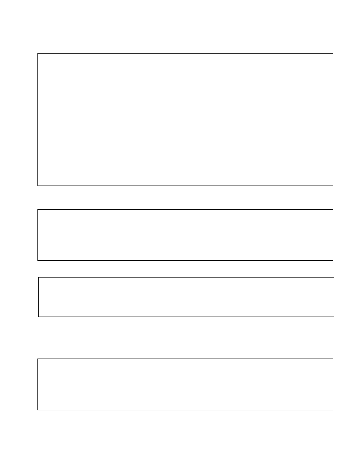
2.1 Package Contents
The dome carton contains the following:
Description Qty
High Speed Dome mechanism 1
Camera Module (Sony 18x or LG27x) 1
Clear Acrylic dome cover 1
Camera shroud (black) 1
Bag of Screws (4xM2*4, 4xM3*5) 1
8 conductor Control/Power/Video harness 1
24VAC transformer (optional) 1
Wall bracket (optional) 1
Instruction manual 1
Camera Ribbon cable (spare) 1
Figure 1. Illustrates the upper layer of the packing material (top half)
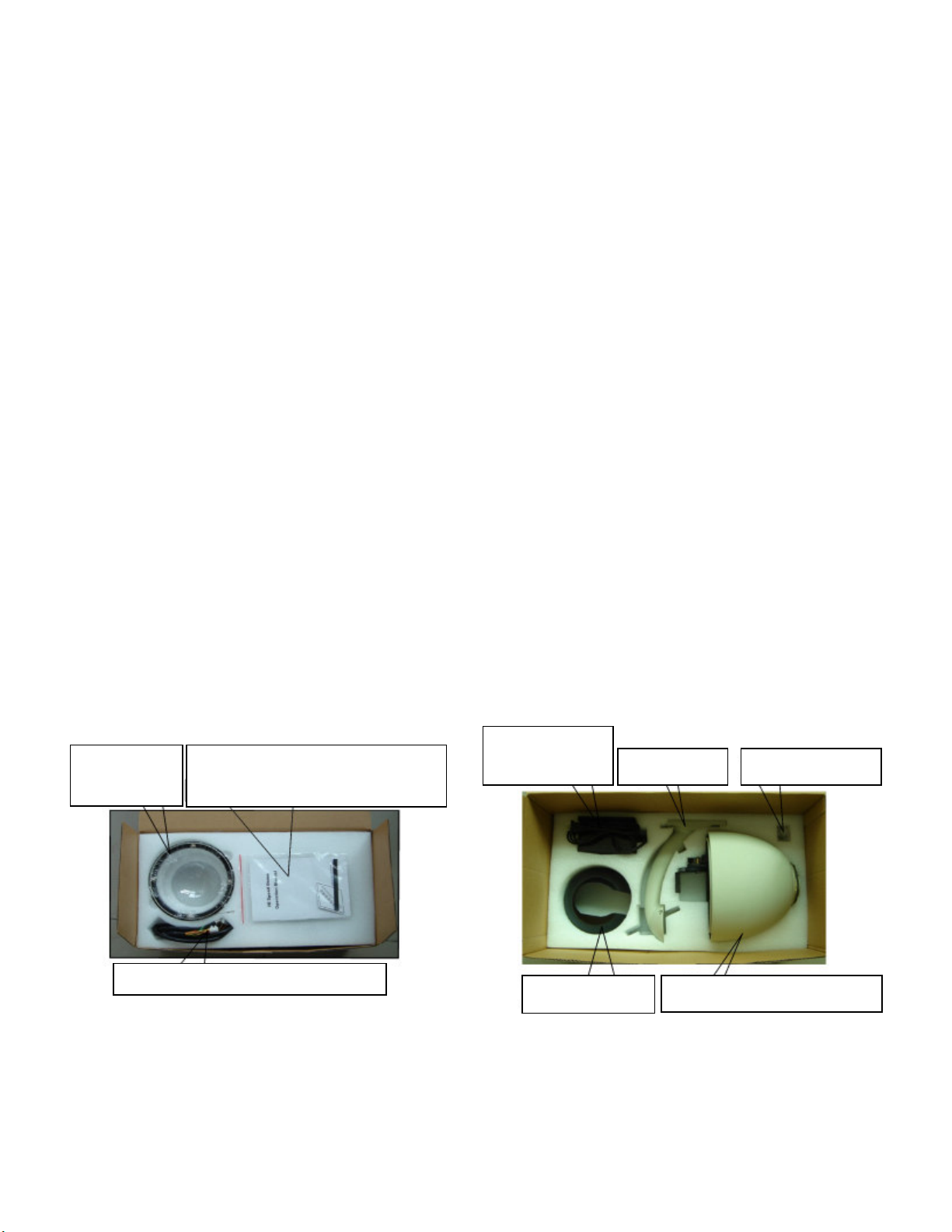
Figure 2. Illustrates the lower layer of the carton (bottom half).
Acrylic
Dome Cover
Manual, Quality certificate,
Spare camera ribbon cable
Fig.1
24 VAC, 2 Amp
Transformer
Camera Shroud
Wall Bracket Shroud Screws
High Speed Dome & Camera
Fig. 2
8

2.2 Camera Installation (Optional)
NOTE: The camera module is pre-installed and tested at the factory according to your
order. You do not need to perform any of the following 3 steps unless you
desire to change or upgrade the camera module.
The followings instructions are for reference purposes only should you need to replace the cable
that connects the camera module to the control board. Figure 3 below illustrates the wiring
configuration of the flex ribbon/cable.
Fig. 3
Step 1
Cable Connector
: Insert FFC Socket of the cable to the relevant port of the base plate on the dome control
board as illustrated in Figures 4 and 5.
Camera ribbon cable
Pull this tab out, and insert the flat ribbon
cable with the metal strip facing upwards
Fig. 4 Fig. 5
Push the tab back in to secure
the camera cable connection.
9

Step 2:
Attention: Exercise care not to scratch the lens when installing the camera. (as a precaution leave
the protective camera lens cap in place until ready to use the dome. Secure the camera to the
corresponding screw holes as illustrated in Figure 6, according to the model and make of the camera,
as different camera models may have different dimensions. Following the installation of the camera
module verify that it does not touch any of the dome parts including the camera shroud and acrylic
dome by gently moving the camera module along the vertical axis.
Install the block video camera module on the vertical axis tray of the dome as
illustrated in Figure 7 using the (4) supplied M2*4 screws.
Fig. 6 Fig.7
Step 3:
Pull this tab out and insert the ribbon cable
Insert the other end of the ribbon cable to the corresponding camera connector as
illustrated in Figures 8 and 9.
Push the tab back in to secure the
camera cable connection.
Fig. 8 Fig. 9
10