

Cossiga Linear Series User Manual

SERVICING
Accessing fans and coil (RF)
key to maintaining your cabinets
USER GUIDE FOR LINEAR SERIES
Thank you for purchasing a Cossiga food display cabinet
This is a guide only. If you are unsure of any aspects of the installation or operation, please contact
us or visit our website www.cossiga.com
SAFETY
Always disconnect this appliance before cleaning and servicing
1. Unscrew base plates
2. Remove trays 3. Lift+ remove grills
Deck height adjustment (RF)
CERAMIC CLEANING
To thoroughly clean your glass ceramic cooktop,
first remove dirt and food with suitable metal
scraper or special sponge for glass ceramic
cooktops.
Once the glass ceramic cooktop has cooled,
put a few drops of suitable cleaner on it and
rub it on with a paper towel, a clean cloth or an
approved cleaning sponge.
CONTROLLER INSTRUCTIONS
DIXELL CONTROLLER ONLY
DEFROST
( RF OR RA UNITS)
UNIT DEFROST WHEN FLASHING
COMPRESSON IS OFF
Use brackets provided to
adjust deck
height
AVOID using ammonia based glass cleaners
DO NOT use abrasive sponges or scouring pads
DO NOT use oven cleaner
DO NOT use earthware or cast iron plates
DO NOT use bathroom or household sponges
COMPRESSOR ON
(RF OR RA UNITS)
HEATING ELEMENTS ON
(HT & BM UNITS)
4. Lift panel to expose fans and coil
Then wipe the glass ceramic cooktop with a
damp cloth and dry it with a clean cloth or an
approved cleaning sponge.
All controllers are preset
AIRFLOW FAN ON
for certified food safety
- avoid unnecessary
adjustments
LET’S
GET
STARTED
Your cabinet has been delivered fully assembled.Please check nothing has moved during transit
1.Check bench cutout is as per table
on website
Servicing should only be carried out by an approved service agent,
registered electrician or refrigeration engineer
Do not use a multi-box or overload your power supply
INSTALLATION
AVOID
• Drafts from doorways
• Airflow from air-conditioning ducts
• Hot air from motors i.e. refrigerators
• Direct sunlight
2. Lift unit into place use lifting brackets
Lifting brackets are
fitted to assist
removing the unit from
the packaging and
placing in cabinetry.
Use a bar that can
fit through the 35 x
35mm square hole (not
supplied)
Lifting
Brackets
Supplied
Bolts retained
for fixing gantry
post
Also applies
to heat
disruption on Bain
Marie and Ceramic
Top units
Use four people lifting
each corner.
After the unit has been
placed in the required
position remove lifting
brackets.Retain bolts
and screws for fixing
the gantry post.
LED LIGHT
SWITCH
PRESS FOR MORE THAN
3 SECONDS TO TURN ON
EXTRA DEFROST
DEFROST
PRESS AND HOLD
FOR 3 SECONDS
SET/CONFIRM
TO ADJUST TEMPERATURE
1 2 3 4
SET POINT WILL
FLASH
PUSH ARROWS TO
ADJUST SET POINT
PRESS SET TO
CONFIRM
ON/OFF
CM & BM
CM & BM
The control
panel is on the
right hand side
when looking
from the rear of
the unit
2.
Plug into socket and screw up.
GANTRY ASSEMBLY
1.
Bain Marie (BM) & Ceramic Top(CM)
Remove side post cover lift up and
out from the base
Position gantry assembly onto base
screw up fixing bolts with washers
from underneath on both sides.
Lamp power cable - feed through
large hole in deck
RF
RF
Refrigerated(RF) gantry screw
down from above.
Screw gantry assembly down on
to base.
3.
Install Cover
On each side post slide up
the post cover panel.
position into clips and pull
down to fit.
NOT
USING A
GANTRY?
GLASS ASSEMBLY
Flat Top
If the gantry is not used a blanking
plate is supplied to cover gantry fixing
holes. Insert into position each side
and fix with a bead of food grade
silione.
SHELF ASSEMBLY
The 4 shelf clamps -
BAIN MARIE INSTALLATION
Your LS Bain Marie is dual purpose and can be run dry, manually filled wet or can be plumbed in for auto fill + drainage
FOR DRY OPERATION
DUAL
PURPOSE
WET OR DRY
OR
Double Curved
See separate glass assembly sheet provided
EXTRACTION FAN
Recommended for optimising
performance. Available as
accessories with detailed
drawings on our website.
Full Square
1.Release bottom screw to
open clamp
2.Screw in clamp to post holes
3.Insert glass shelf and centre.
Tighten shelf clamps using
underneath scew to suit.
NOTE: LS5 - LS6 units come
with a two piece glass mid shelf
and bracket. The bracket is
fixed to the middle underside of
the lamp box
SEE PAGE 19 LS FULL SPEC TECH SPCS FOR DETAILS
BAIN MARIE
Needs to be kept clean to stop
the build up of lime scale
Clean Daily
Clean with hot soapy
water
Rinse + Dry
A commerical descaler may be
required periodically
HALOGEN LAMPS
Life span of each bulb is between 1500 and 2000 hours which is approximately 7-10
weeks when running 24/7 or 27-35 weeks when running at 8 hours a day
Bulbs are incredibly sensitive to vibration and can cause premature blowing or
shattering.Ensure doors are not slammed and do not allow steam moisture to build
on globes
Use stainless bracket to
disengage float switch
IF YOUR BAIN MARIE HAS NO POWER?
Check the ‘trip switch’ in the electrical box
RESET
If it continues to trip please call a service techician
TO AVOID STEAM ON GLASS?
Ensure pans fit tight - NO GAPS
+
Leave rear door slightly open
Light Bulb Type
64243011
240V 300W
Clear Quartz Jacket
Halogen Infra-Red
Catering Lamp
R7s Cap
Ensure condensor unit has adequate
ventilation as per Cossiga
specifications
key to the efficient running and long life
Make sure the fan is drawing cool
No front ventilation
required if back is
completely clear
Fans extracting
when doors
closed
ALL SPECIFIC MODEL VENTILATION DRAWINGS ARE AVAILABLE ON OUR WEBSITE
VENTILATION MUST BE CORRECT FOR WARRANTY TO BE VALID
and hot air can escape
air in
No doors or
covers ensure
optimal
performance
Air IN
must be separated
from
Air OUT
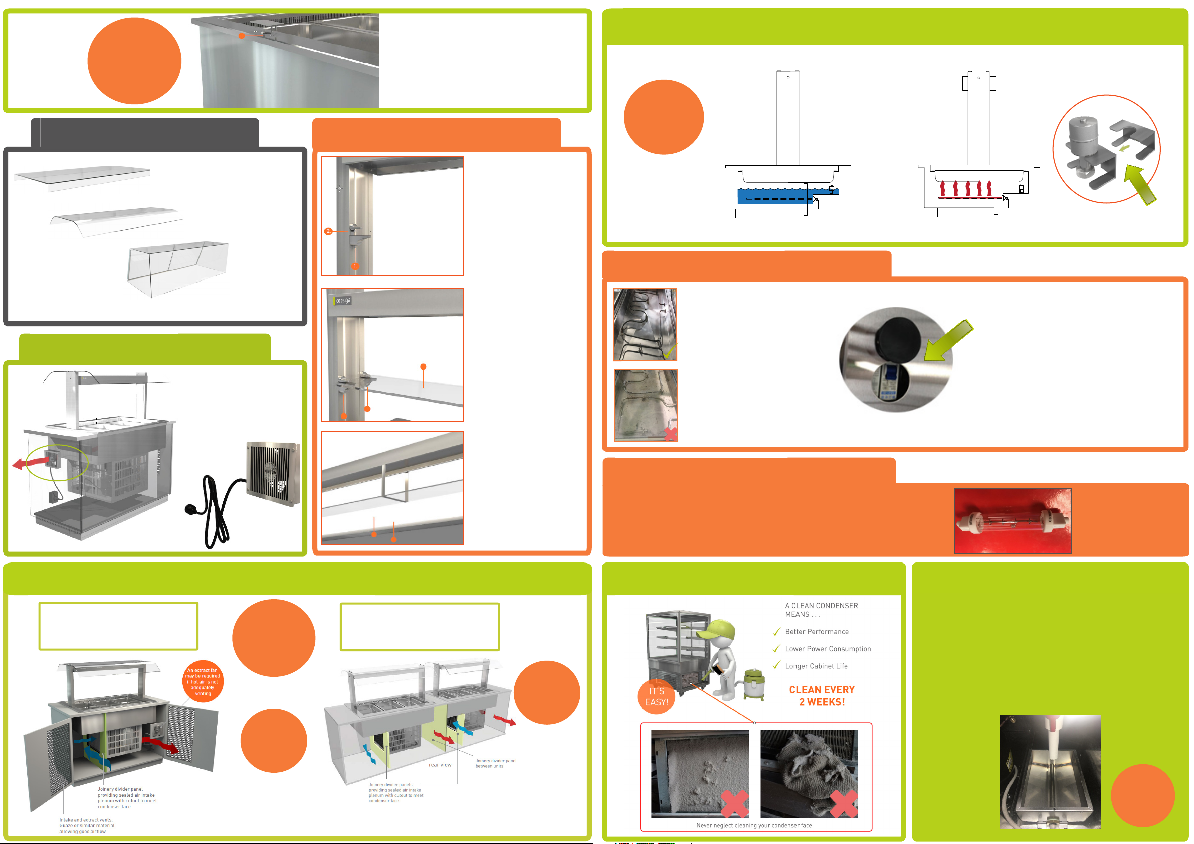
CONDENSER CLEANING
CONDENSER CLEANINGREFRIGERATION VENTILATION
EVAPORATION PANS
RF UNITS
Designed to boil off excess water produced by your cabinet
NEED TO BE KEPT CLEAN!
Disconnect the power and unscrew and remove the rear
cover to access pan
Remove water and wipe pan
( CAUTION: MAY BE HOT)
CLEAN
ME!
 Loading...