

Cosmotec WRA 13-20, WRA 35-45-58-70, WRA 85, ORA 34-43-58-70, WRA 95-A3-A6 Series Manual
...
EN
rev 09.2017
2/34
rev 09.2017 - ©STULZ S.p.A. - all rights reserved
INDEX
1.0 GENERAL INFORMATION
GENERAL INFORMATION
1.1 LIST OF ATTACHED DOCUMENTS
1.2 WARNINGS
1.3 HANDLING AND STORAGE
STORAGE
HANDLING AND TRANSPORTATION
1.4 IDENTIFICATION AND TECHNICAL DATA
LABELS MOUNTED ON THE MACHINE
LEVEL OF PROTECTION
PRINCIPLE OF OPERATION
CONTROL AND SAFETY DEVICES
NOTE FOR WATER CONDENSED CHILLERS
NOTE FOR OIL CHILLERS
SIZE OF CHILLERS
TECHNICAL DATA
CORRECTION FACTORS TABLE
PREVALENCE OF THE STANDARD PUMPS
1.5 INTENDED AND UNINTENDED USE
1.6 SAFETY
1.7 RESIDUAL RISK
2.0 INSTALLATION AND CONNECTIONS
I
N
N
S
S
T
T
A
A
L
L
L
L
A
A
T
T
I
I
O
O
N
N
A
A
N
N
D
D
C
C
O
O
N
N
N
N
E
E
C
C
T
T
I
I
O
O
N
N
S
S
2.1 GENERAL INFORMATION
2.2 HYDRAULIC CONNECTIONS
2.3 ELECTRICAL CONNECTIONS
2.4 OPERATIONS
WORK CONDITIONS TABLE
WATER QUALITIY TABLE
NOTE FOR OIL CHILLERS
3.0 ORDINARY MAINTENANCE
CONTROLS AND
MAINTENANCE
3.1 SPECIAL MAINTENANCE
3.2 COOLANT LEAKS CHECK
3.3 SEARCHING FOR DEFECTS
3.4 DISMANTLING AND DISPOSAL
4.0 GENERAL WARRANTY CONDITIONS
GUARANTEE
AND
DELIVERY
4.1 DELIVERY
3/34
rev 09.2017 - ©STULZ S.p.A. - all rights reserved
1.0 GENERAL INFORMATION
This manual contains all the chiller installation, use and maintenance regulations, highlighting the related
risks and dangers.
It was expressly designed to allow its staff to use it in a safe and secure manner. Read all the information
therein carefully and be careful of the regulations marked with a symbol on the side. If not observed,
they can cause damages to things, people, the environment and the chiller.
The manufacturer is not liable for any improper use of the chiller, for unauthorized changes and for
not following the instructions contained in this manual.
The manual must be kept by the contractor and made available to the staff in charge of installing,
running and maintaining the chiller.
1.1 LIST OF ATTACHED DOCUMENTS
List of documents provided with the chiller:
Manual Part II
Thermostat Manual and Configuration Chart
Pump Manual
Manual of Various Options (if requested by the client)
1.2 WARNINGS
The chiller was designed and built for professional use based on the current regulations (see the declaration
of conformity in the Manual Part II).
The chiller is built with quality materials that underwent laboratory exams to verify its reliability and safety. It
was inspected and put under warranty.
This manual is intended for the following professionals:
INSTALLER is required to verify the correct chiller installation based on the workplace safety regulations and
the instructions contained in this manual.
OPERATOR (or user) is required to know all the workplace safety regulations, the instructions contained in
this manual for its correct use and the ordinary maintenance of the chiller.
MAINTENANCE TECHNICIAN (or assistance technician) authorised by the chiller manufacturer for technical
assistance, special maintenance and repairs.
Qualified staff means those professional figures who, given their training, education and experience as well
as their specific knowledge of the workplace safety and accident prevention regulations, are authorised by
the safety manager to perform the aforementioned activities.
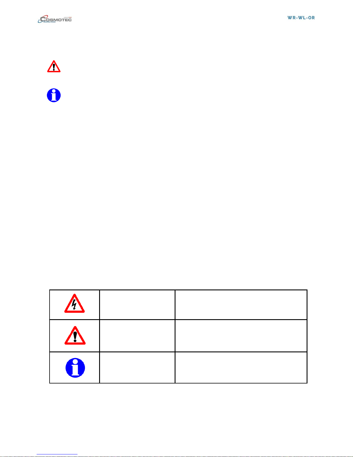
DANGER
SITUATIONS WHERE THERE IS A RISK OF
ACCIDENT FOR THE OPERATOR
AND THE RISK OF DAMAGE TO THE CHILLER
ATTENTION
INFORMATION OR WARNING TO BE CAREFUL
WHEN COMPLETING A PROCEDURE OR
COMMAND
INFORMATION
IMPORTANT INFORMATION
4/34
rev 09.2017 - ©STULZ S.p.A. - all rights reserved
1.3 ACCEPTANCE, HANDLING AND STORAGE
ATTENTION The chiller must be transported and moved without liquid(s) in the tank(s) (only for
models with a tank).
STORAGE
The chillers are packaged using standard packaging (unless otherwise agreed).
Loading and unloading must be done indoors.
Standard packaging does not protect the chiller from rain and inclement weather
Standard packaging is not suitable for transportation by boat
Standard packaging is not suitable for transportation by air
The environmental conditions for storage are the following:
-min ambient temperature -10°C for R134a/ R407C/ R404A/ R410A
-max ambient temperature +60°C for R134a
-max ambient temperature +50°C for R407C/R404A
-max ambient temperature +45°C for R410A
- max humidity UR 90%
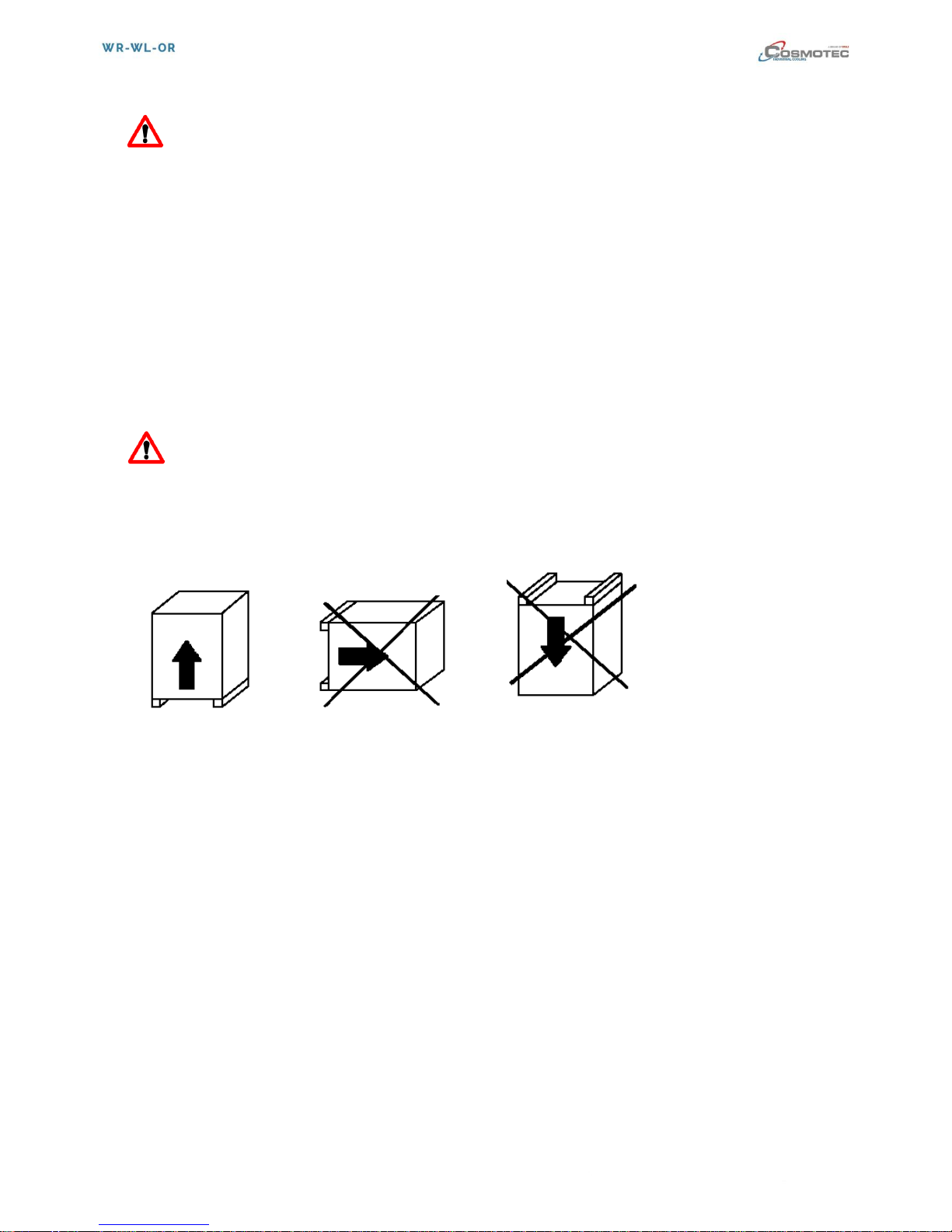
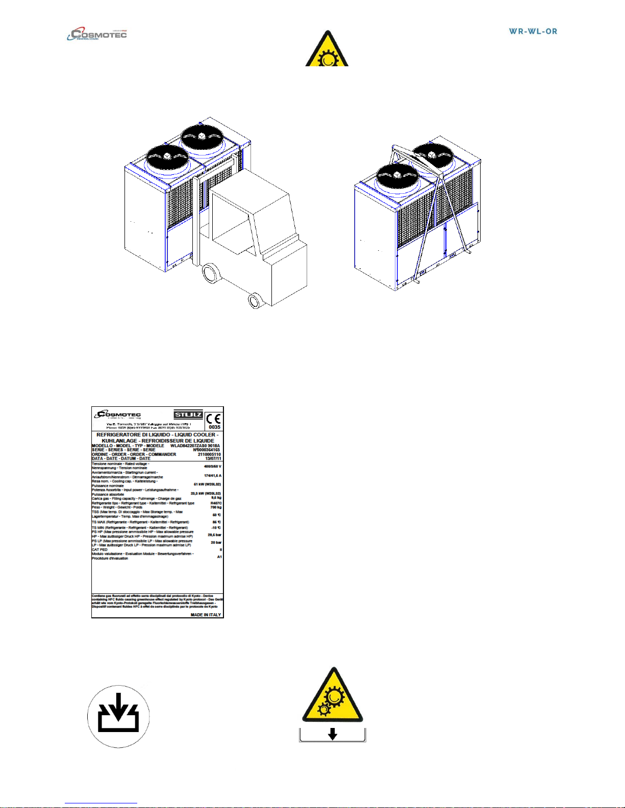
HANDLING AND TRANSPORTATION
The chiller must be lifted safely without inclining it and laying it on its side using the appropriate
equipment with the following characteristics:
-adequate capacity to lift the load
-the load must be balanced to avoid impact
-do not do any brusque and/or violent movements
-do not place other objects on the chiller
Examples:
5/34
rev 09.2017 - ©STULZ S.p.A. - all rights reserved
1.4 IDENTIFICATION AND TECHNICAL DATA
The chiller is identified with a technical data label that includes the following information:
TYPE OF LIQUID TO CHILL:
Ex. WRA3541N07C000 water (water solutions +
additives)
Ex. WLAD842207C000 water (water solutions +
additives)
Ex. ORA9542207C000 oil (see note for oil chillers in chap.
2.4 Operations)
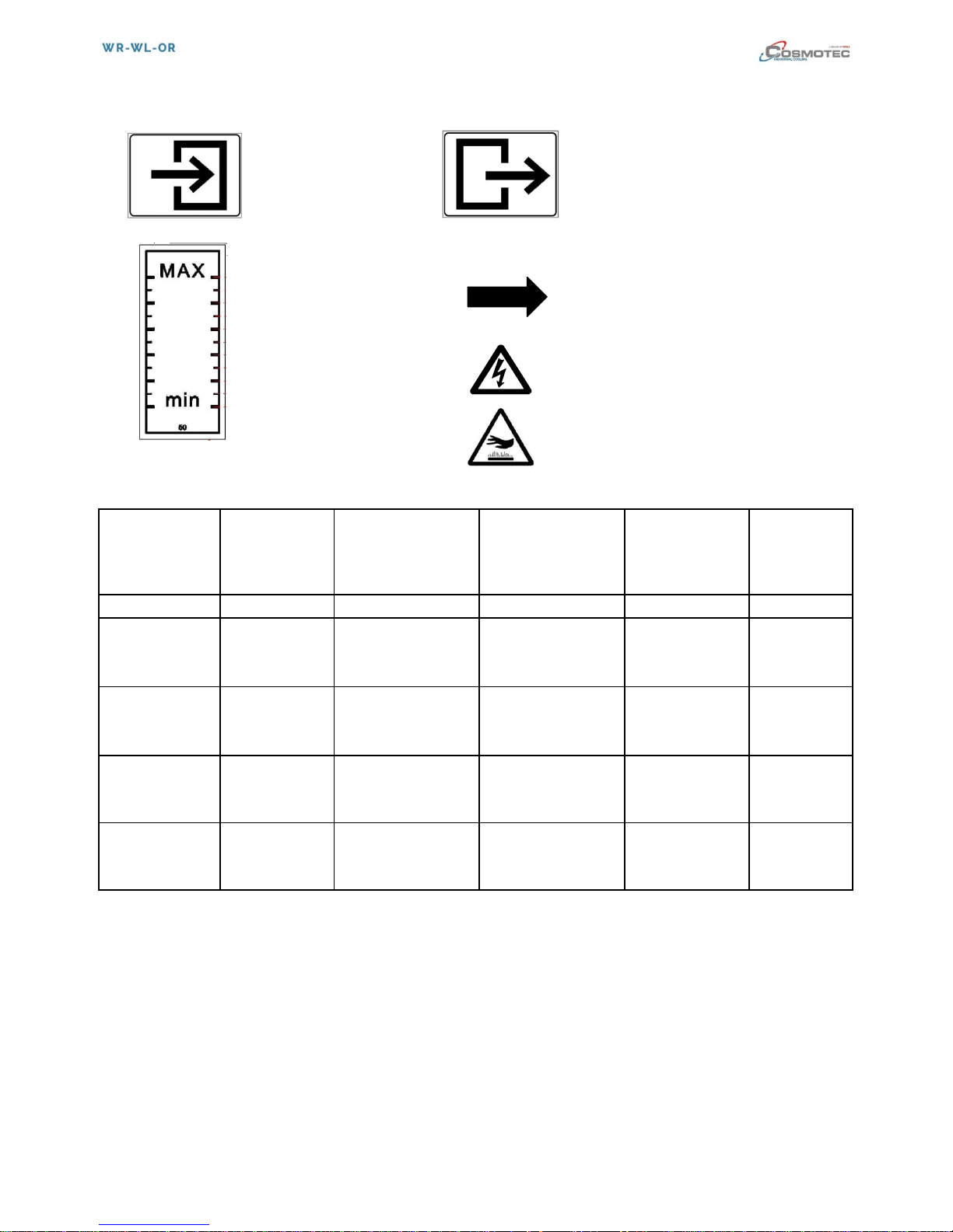
LABELS MOUNTED ON THE MACHINE:
MOVING PARTS HAZARD
FILING UNLOADING
TANK TANK
6/34
rev 09.2017 - ©STULZ S.p.A. - all rights reserved
INCOMING OUTGOING
FLUID FLUID
CHILLER CHILLER
TANK LEVEL ROTATION DIRECTION
ENGINES
RISK OF TENSION
ATTENTION! HOT SURFACES
LEVEL OF PROTECTION
SERIES
MODELS
INSTALLATION
POWER
CONTROL
PANEL
PROTECTION
(mounted on the
machine)
ENGINE
PROTECTION
(from the
external
environment)
WLA Compact
ALL
INDOOR
230/1/50-60
IP 21
IP 21
WRA Vertical +
ORA O-FLOW
WRA 13-20-35-
45-58-70-85
ORA 20-34-43-
58-70
INDOOR
230/1/50-60
400/3/50 460/3/60
IP 21
IP 21
WRA Vertical +
ORA O-FLOW
WRA 95-A3-
A6-A8-B4-B8-
C2-C8-D8
ORA 95-A3-A6
OUTDOOR
400/3/50 460/3/60
IP54
IP 44
WLA Precision
ALL
OUTDOOR
400/3/50 460/3/60
IP54
IP 44
WLA Precision
R410A
ALL
OUTDOOR
400/3/50 460/3/60
IP54
IP 44
The IP (International Protection) code is a convention defined in EN 60529 standard (implemented
by CEI as CEI 70-1 standard) to identify the degree of protection provided by enclosures for
electrical and electronic equipment against the penetration of external agents in solid or liquid form.
PRINCIPLE OF OPERATION
The chiller is designed to chill liquids and is suitable for industrial environments. Its use allows the
temperature of the liquid to chill to be controlled.
The principle of operation is the following:
The compressor compresses coolants, bringing it to a high pressure and temperature; the gas passing
through the condenser is chilled and liquefied, releasing heat into the environment. Pushed toward the filing
system or valve, the liquid gas drops in pressure which helps its evaporation, which occurs in the evaporator,
in contact with the liquid coming from the catchments that is chilled.

7/34
rev 09.2017 - ©STULZ S.p.A. - all rights reserved
CONTROL AND SAFETY DEVICES
- Safety pressure switch: It stops the compressor operation when the internal pressure of the circuit
exceeds the calibration level - (High pressure switch)
- Safety valve (when installed): It vents the internal pressure of the circuit to the atmosphere if there
would be an abnormal increase in pressure with the equipment in operation or switched off
NOTE FOR WATER CONDENSED CHILLERS
For chillers WRW, WLW AND ORW with a water condenser in the heat exchanger, follow the following
instructions:
Condensation condenser temperature water entering to the exchanger operation limits. Min/Max 10-30°C.
Recommended filtering level μm 500.
The minimum capacity is suggested in the technical chart attached to the machine and varies to vary the
required chiller capacity or for any special client requests, which are occasionally analyzed by the technical
office.
The adjustment of the water pressure valve on the water side is done when it is inspected in the plant. For
any problems/questions, contact aftersales.
A short discussion about the heat exchangers used to condense the water chiller:
Load loss
The load loss values that are found in the heat exchangers can be estimated at a minimum of 0.1 bar and a
maximum of 0.5 bar.
Dirtiness and Corrosion
To increase the efficiency of the exchangers, reduce, or avoid, build-ups due to materials in the liquids, for
example, mud, sand, etc, which often occurs in exchangers powered by rainwater, cooling towers, river
water, lake water, etc. They are not suited for salt water.
Dirtying due to carbonate would seem to be different since, as is known, they cannot be influenced by the
operation of the exchanger's temperature: precipitation starts when the water that is contained therein
exceeds the threshold of 45°C.
The heat exchangers are clean with suitable fluids for this purpose. Problems of corrosion are limited given
the specific resistance of the materials used for construction.

8/34
rev 09.2017 - ©STULZ S.p.A. - all rights reserved
SIZE OF WLA COMPACT
L P H K J O IN/OUT
UNI ISO228
WLA 14-20
604
480
388
56
54
90
½ ”G
WLA 28-41-45
807
494
504
70
54
90
½ ”G
MOD.
(mm)
9/34
rev 09.2017 - ©STULZ S.p.A. - all rights reserved
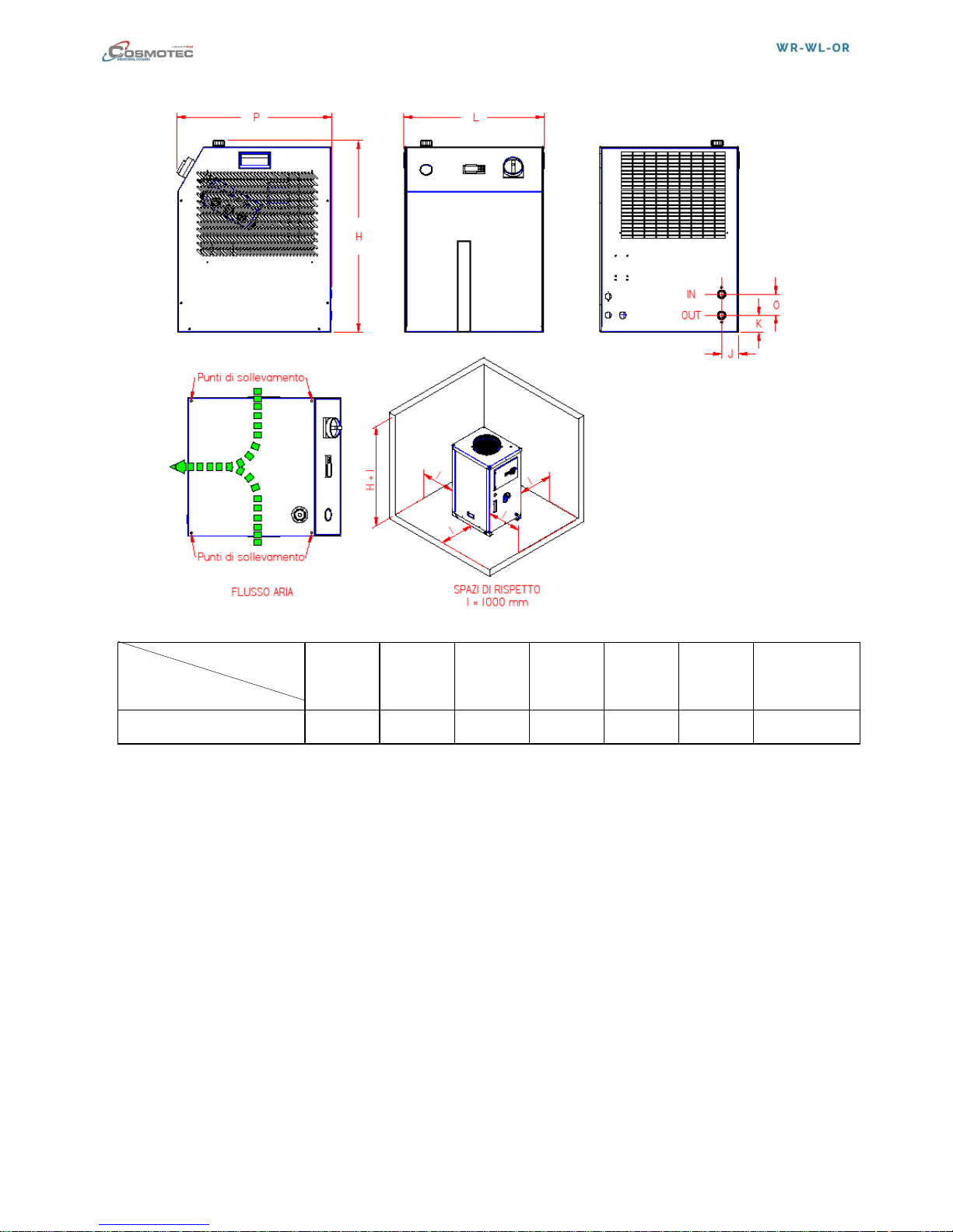
WRA VERTICAL + ORA O-FLOW SIZE
L P H K J O IN/OUT
UNI ISO228
WRA 13-20
480
525
686
87
59
72
½ ”G
MOD.
(mm)

10/34
rev 09.2017 - ©STULZ S.p.A. - all rights reserved
L P H K J O IN/OUT
UNI ISO228
ORA 20
420
580
720
90
54
72
½ ”G
WRA 35-45-58-70
ORA 34-43-58-70
570
740
1146
135
85
130
¾ ”G
WRA 85
570
740
1220
135
85
130
¾ ”G
WRA 95-A3-A6
ORA 95-A3-A6
735
926
1500
142
121
130
1 ”G
WRA A8-B4-B8-C2
900
1200
1930
165
170
150
1 ¼”G
WRA C8–D8
1250
1250
2000
190
170
150
1 ½”G
MOD.
(mm)

11/34
rev 09.2017 - ©STULZ S.p.A. - all rights reserved
SIZE OF WLA PRECISION
L P H K J O IN/OUT
UNI ISO228
WLA B8-C2
700
1650
1450
615
98
150
1 ¼”G
WLA C8-D8
1140
2000
1820
615
98
150
1 ½”G
WLA G2-H8
1140
2000
1820
615
98
150
1 ½”G
SIZE OF WLA PRECISION R410A
MOD.
(mm)
 Loading...