

Page 1
62417003 - R00 07-12-2007_GB-IE
MODELS:
NOV ADENS 24 - 24B
NOV ADENS 24C - 24P
NOV ADENS 34 - 34B
NOV ADENS 34C - 34P
NOV ADENS 45A - 45C
USERS’ MANUAL FOR GAS BOILERS
PLEASE READ THE MANUAL CAREFULLY: IT CONTAINS IMPORTANT INFORMATION
REGARDING SAFETY, INSTALLATION, USE AND MAINTENANCE OF THE APPLIANCE
Page 2

2
T able of contents
1 - GENERAL SAFETY WARNINGS........................................................................... 3
2 - GENERAL INFORMATION ..................................................................................... 4
2.1 - Introduction ............................................................................................................................... 4
2.2 - Description of models ............................................................................................................... 4
2.3 - Manufacturer ............................................................................................................................. 4
2.4 - Key to symbols used ................................................................................................................. 4
2.5 - Warranty ................................................................................................................................... 4
3 - USE.......................................................................................................................... 5
3.1 - Check that the cocks are open .................................................................................................. 5
3.2 - Check heating system pressure ................................................................................................ 5
3.3 - Overview...................................................................................................................................5
3.4 - Displays.................................................................................................................................... 6
3.5 - St art-up procedure .................................................................................................................... 6
3.6 - “Users’ menu”............................................................................................................................ 6
3.7 - Summer mode .......................................................................................................................... 7
3.8 - Winter mode .............................................................................................................................7
3.9 - Adjusting the heating temperature .............................................................................................7
3.10 - Adjusting the heating temperature with climatic adjustment......................................................7
3.1 1 - Domestic hot water temperature adjustment ............................................................................ 8
3.12 - Room temperature adjustment ................................................................................................ 8
3.13 - Errors and alarms ................................................................................................................... 8
3.14 - Pressure gauge ......................................................................................................................8
3.15 - Shutdown procedure ............................................................................................................... 9
3.16 - Precautions against freezing ................................................................................................... 9
3.17 - Flue gas discharge ................................................................................................................. 9
3.18 - Operating anomalies............................................................................................................... 9
3.19 - Remote control (on request) .................................................................................................. 10
4 - Warranty................................................................................................................. 11
4.1 - General warranty conditions ....................................................................................................11
4.2 - Instructions for filling in the warranty card ................................................................................. 11
4.3 - Warranty limits......................................................................................................................... 11
Page 3

3
If you smell gas
l Close the gas cock.
l Ventilate the room.
l Do not use any electrical appliances, telephone
included.
l Immediately call a qualified technician or the gas
board from another room or building. If you cannot
contact them, call the Fire Brigade.
If you smell product of the combustion
l Switch off the appliance.
l Ventilate the room.
l Call a qualified technician.
In the presence of water leaks
l Switch off the appliance.
l Close the central water mains cock.
l Call a qualified technician.
Explosive or easily inflammable products
Do not store or use explosive or easily inflammable
materials such as paper, solvents, paints, etc..., in
the same room as the boiler.
In the event of a breakdown
In the event of breakdown and/or malfunctioning of the
appliance, disconnect it, do not attempt to repair it or
intervene in any way whatsoever. Cont act a qualified
technician.
Qualified technicians
Qualified technicians are personnel with specific,
technical training in the heating system component
sector and with regards to domestic hot water
production for public use, fuel gas systems and
electrical systems. These individuals must have the
legally required qualifications.
1 - GENERAL SAFETY WARNINGS
FThis booklet forms an integral and essential
part of the product and must be carefully kept
by the user, for any future consult ation. Ensure
that this booklet is handed over to the new
owners and/or installer if the appliance should
change hands or be moved for any reason
whatsoever.
FThe installation, setting and modification of
the gas appliance must be carried out by
qualified technicians, in compliance with local
and national norms and the instructions in the
installation and maintenance manual.
FFlue pipes must not be modified in any way.
FThe user, in accordance with these instructions,
must keep the appliance in satisfactory running
order and ensure reliable, safe operating.
F The user is responsible for employing a
qualified technician to carry out maintenance
work on the appliance in compliance with local
and national norms and the matters stated in
the installation and maintenance manual. We
highly recommend arranging a regular
maintenance contract with a qualified
technician.
FThe manufacturer cannot be held responsible
for any damage to people, animals or property
caused by inadequate maintenance.
FDo not obstruct the ends of the venting pipes .
FThe technician will explain the functioning,
use of the appliance and use of the system to
the user.
FThe user must be familiar with filling and
discharge procedures for the boiler, and the
control and eventual adjustment of water
pressure in the heating circuit.
FThe user must be familiar with the
procedures for fully optimizing the
conservation of energy and avoiding waste
of the entire heating system.
FRegularly check the system pressure using
the pressure gauge “13” (see figure 1) to
ensure a reading between 1 and 1.5 bar.
FWait a few minutes after opening the gas
supply cock before starting the boiler up.
FDo not leave the boiler switched on
unnecessarily if it is not going to be used for
long periods; in such situations, close the gas
cock and disconnect from the electricity
mains supply . Consult section 3.16 if there is
a risk of freezing.
FDo not touch the flue gas discharge pipe,
during and for some time after operations, as
it is very hot.
Page 4
4
2 - GENERAL INFORMATION
2.1 - Introduction
Congratulations!
Y ou have ef fectively purchased one
of the best products on the market.
Each single part is built, tested and
assembled, with pride, at the
COSMOGAS factories, thereby
guaranteeing optimum quality
control.
Thanks to on-going research
carried out by COSMOGAS, this
product has been conceived and is
considered to be the best in its
class with regards to respect for
the environment, since it falls within
class 5 (less polluting) envisaged
by technical norm EN 297 (and EN
483) and has an elevated efficiency ,
4 stars as per EC Directive 92/42/
EEC. Great importance is also
given to the end of the appliance’s
useful life. All its components can
easily be separated into similar and
completely recyclable parts.
2.3 - Manufacturer
COSMOGAS srl
Via L. da Vinci 16
47014 - Meldola (FC) IT AL Y
T el. +39 0543 498383
Fax. +39 0543 498393
www.cosmogas.com
info@cosmogas.com
2.4 - Key to symbols
used
General danger!
Failure to observe this warning may
compromise the smooth running of the
appliance or cause serious damage to
individuals, animals or property .
l Operation symbol
F Important indication symbol
2.5 - W arranty
See section 4
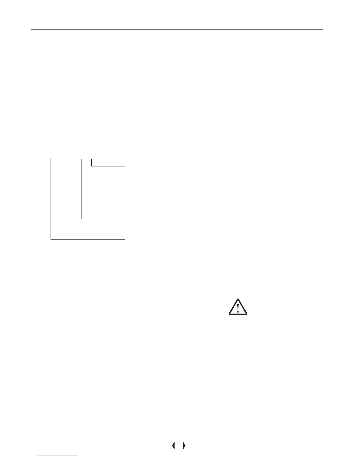
NOVADENS XXYYYY
“ “ =
Boiler with exchanger sanitary to partial accumulation;
“A” = Boiler for only heating without integrated pump;
“B” = Boiler which can be combined with BWR C series storage tank;
“C” = Boiler for only heating with integrated pump;
“P” = Boiler with exchanger secondary for D.H.W., to plates;
“0834” = Boiler for low temperature central heating systems.
24 = Boiler with maximum input heat of 25 kW
34 = Boiler with maximum input heat of 34.8 kW
Gas-fired, condensing, hot water boiler, with sealed combustion chamber
and pre-mix burner, for heating and domestic hot water production.
2.2 - Description of
models
Page 5
5
3 - USE
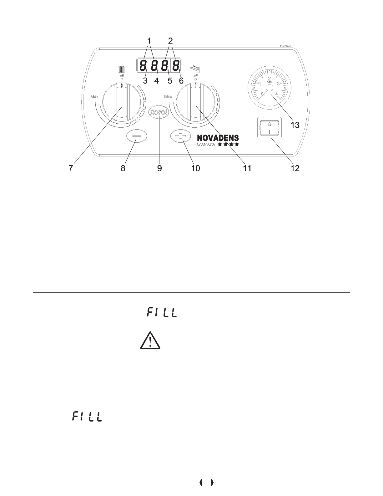
Figure 1 - Instrument panel
3.1 - Check that the
cocks are open
- The gas cock must be open;
- any supply and return valves must be
open;
- any hot and cold water valves must be
open.
3.2 - Check heating
system pressure
If the pressure inside the heating circuit
falls below 0.5 bar, the appliance
switches off and the display 1 as per
figure 1, shows to indicate
that it is necessary to restore the correct
pressure. Proceed as follows:
l open the filling cock (see figure 5)
turning it in a counter-clockwise
direction;
l check the pressure on the pressure
gauge “13” of figure 1, it must reach a
pressure of 1.5 bar and the indication
must disappear;
l close the filling cock (see figure 5)
turning it in a clockwise direction.
CAUTION!!! During normal
operations, the filling cock (see
figure 5) must always remain in the
closed position.
If, with time, the pressure drops, restore
the correct value. This operation may
have to be repeated several times
during the first month of operations to
remove any gas bubbles present.
3.3 - Overview
The boiler is pre-set with standard
parameters. However , it is possible to
make a number of changes or consult
the parameters by means of using the
“Users’ Menu” (see section 3.6).
During functioning display “1” of figure 1
displays the status of the boiler and
display “2” (see figure 1) shows the
value of the parameter. The various
operating statuses are shown in the
table in figure 2.
Within the “Users’ Menu” (see section
3.6) it is possible to check the last
lock-outs or errors which have occurred.
In addition to the operating modes, the
instrument panel provides important
information on the current functioning of
the boiler, via the indicators “3”, “4”, “5”
and “6” of figure 1. In particular:
- the indicator “3” displays whether the
burner is functioning (on) or whether it is
off (blinking);
- the indicator “4” displays whether the
domestic hot water service is on or off;
- the indicator “6” displays whether a
heating service request is active (on) or
nor (off).
1 - Parameter display .
2 - Display of values adopted by parameters.
3 - Burner status indicator . On = burner on, flashing = burner off.
4 - Domestic hot water service status indicator. On = d.h.w. on, Off = d.h.w. off.
5 - Indicator of decimal of value displayed.
6 - Heating service status indicator. On = heating on, Of f = heating off.
7 - Heating temperature and start control.
8 - Key for decreasing parameter values.
9 - Key for resetting shutdowns and for scrolling the list of parameters.
10 - Key for increasing parameter values.
1 1 - Domestic hot water temperature and start control.
12 - On/off power switch.
13 - Heating circuit pressure gauge.
Page 6

6
3 - USE
Figura 2 - Parameters displayed during functioning
P ARAMETER DESCRIPTION ON DISPLA Y “2” (figure 1)
Boiler on stand-by or on hold (no heating or hot water request
exists)
Anti-freeze function active
Caution!!! Domestic hot water active for more than 120 minutes
(turn domestic hot water to OFF position in order to reinstate
heating). Check that there are no leaking taps. If the problem
persists, contact a professionally qualified technician
Caution!!! System pressure too low, fill system follow section
3.2.
Domestic hot water service on
Heating service on
Boiler in lock-out mode. To reset it, press the
button. If
the lock-out occurs frequently, cont act a professionally qualified
technician.
Boiler fault. Contact a professionally qualified technician
Auto-purging procedure in progress . It will end within 2 minutes
Boiler temperature (°C)
Boiler temperature (°C)
Boiler temperature (°C)
No display
Domestic hot water temperature (°C)
Heating temperature (°C)
Lock-out code (see installation and
maintenance manual)
Error code (see installation and maintenance
manual)
Boiler temperature (°C)
POSSIBLE DISPLAYS
3.4 - Displays
During normal operations, the parameters’ display “1” and the values’
display “2” (see figure 1) remain permanently on (if the ”Energy Saving” mode
has not be activated).
The parameters which can be displayed
are shown with their meaning in the
table shown in figure 2.
3.5 - Start-up
procedure
l Open the gas cock;
l switch on electric power to the boiler;
l If the display shows code 21, it
means that the polarity has not been
observed between phase and neutral;
l on initial start-up, the appliance carries
out an auto-purging cycle lasting two
minutes. This is indicated by the
appearance of on the display;
l wait two minutes until the end of the
auto-purging cycle;
l turn knob “7” of figure 1 until it reaches
the heating temperature desired. Turn
knob “1 1” of figure 1 until it reaches the
domestic water temperature desired.
The flame control appliance will start-up
the burner.
If the burner fails to ignite within 5
seconds, the boiler will automatically
attempt ignition another three times, after
which if it fails to start-up, it will shut down
and the display will show 01.
Press the button in order to re-set
normal operating conditions. The boiler will
automatically attempt another start-up.
CAUTION!!! If the appliance
frequently shuts down, contact a
qualified technician to restore normal
running conditions.
Now the boiler will continue to operate in
relation to the service requested and will
indicate the following on display “1”:
if a domestic water request is active;
if a heating request is active;
if there is no domestic water or heating
request active.
3.6 - “Users’ menu”
Entry into the “Users’ Menu” is shown
by display “1” blinking. In order to access
the “Users’ menu” just:
l press the button for 2 seconds
until the display starts to blink;
l press and release the button
several times until the parameter
desired is displayed;
l by means of the or keys,
it is possible to change the value of
the parameter;
l press in order to confirm the
amended data and pass onto the next
parameter;
l Once you have reached the end of the
menu, on the last , the display
“1” stops blinking indicating exit from
the “Users’ menu”.
If no key is pressed for more than 60
seconds, one automatically exists the
menu. Any change in the p arameters not
confirmed using the button, will
be lost.
In this menu it is possible to consult and/
or change the parameters indicated in
figure 3.
Page 7

7
3 - USE
Figure 3 - Parameters within the “Users’ Menu”
“USERS’ MENU”
Adjustment of the gradient of the line as per figure 4. Visible only with climatic adjustment active.
(See installation and instruction manual).
Adjustment of “Minimum heating temperature”.
Visible only with climatic adjustment active. (See
installation and instruction manual).
Adjustment of “Maximum heating temperature”.
Visible only with climatic adjustment active. (See
installation and instruction manual).
Adjustment of the parallelism “b” of the line as per
figure 4. Visible only with climatic adjustment
active. (See installation and instruction manual).
Display of calculated heating temperature (if
climatic adjustment active) or display of temperature set via the control “7” as per figure 1.
Display of domestic hot water temperature set via
the control “11” as per figure 1.
Display of last error registered.
Display of last block which occurred.
Setting range: 0.1-5.0
Setting range: 20°C-60°C for radiant panels, 30°C - 60°C
for radiators.
Setting range: 45°C for radiant panels, 80°C for radiators.
Only display . The regulation is carried out using the control
“7” as per figure 1. It can adopt values ranging between 10°C and +10°C
Only display. It can adopt values ranging between 20°C
and 80°C
Only display. It can adopt values ranging between 40°C
and 70°C
Only display. It can adopt the values indicated in the
installation and maintenance manual
Only display. It can adopt the values indicated in the
installation and maintenance manual
PARAMETER DESCRIPTION INFORMATION ON DISPLAY “2”
3.7 - Summer mode
To disable the heating functions for a
prolonged period, leaving only the
domestic hot water function, switch the
heating temperature to minimum, until the
wording OFF appears, by turning knob “7”
of figure 1.
3.8 - Winter mode
In Winter mode, by means of the pump ,
the boiler sends the water to the system
at the temperature set using knob “7” of
figure 1.
When the temperature inside the boiler
reaches the temperature set, the burner
starts to modulate the flame so as to
reduce the output to a minimum. If the
temperature rises further, the burner shut s
down.
Simultaneously, the pump which sends
the water to the system is switched on
and off by the room thermostat. This can
be noted, because indicator “6” of figure
1 switches on and off in correspondence
with the on and off of the pump.
At first the pump may make a noise. This
is due to the presence of residual air in
the hydraulic system which will soon
disappear on its own.
We recommend keeping the temperature
set using knob “7” at the point shown by
the symbols on the panel for a rational
use of the boiler. If it is a p articularly cold
Winter and it is difficult to maintain the
desired temperature, turn knob “7” to
gradually higher values.
3.9 - Adjusting the
heating temperature
To set the heating temperature, turn
control knob “7” of figure 1. As soon as
the knob is touched, will blink on
display and the temperature being set will
appear on display “2”. As a rule, it is
sufficient to turn control knob “7” to the
half-way position. If it is a particularly cold
Winter, progressively increase the
temperature by rotating control “/”.
3.10 - Adjusting the
heating temperature
with climatic
adjustment
The adjustment of the heating
temperature, in the event that climatic
adjustment has been set, is carried out
by turning control “7” as per figure 1. As
soon as the control is touched, display
“1” show a flashing and display “2”
shows the value in °C of translation on a
parallel with the adjustment curve (see
figure 4, detail “b”. As a rule, it is sufficient
to adjust control “7” to the half-way
position. If the Winter is particularly rigid,
progressively increase the temperature
using control “7” until the temperature
inside the rooms is satisfactory. If the
comfort produced by the climatic
adjustment is not satisfactory (too hot,
too cold, room temperature not constant)
Page 8

8
3 - USE
Outside temperature (°C)
Supply temperature (°C)
Figure 4 - Graphs of the climatic adjustment for high temperature
systems
Outside temperature (°C)
Supply temperature (°C)
OA = Inclination of the line
Ob = Minimum heating
temperature
Oc = Maximum heating
temperature
br = “Fix point” of the angle
fulcrum of the line
b = parallel shift of the line
(possible using control “7” of
figure 1)
just enter the users’ menu and adjust the
parameters corresponding to figure 4. It
is necessary to consider that the thermal
inertia of a dwelling is extremely high,
therefore each time you make a change,
wait at least 24 hours to see the result.
3.11 - Domestic hot
water temperature
adjustment
To adjust the domestic hot water, turn
control knob “1 1” of figure 1. As soon as
the knob is touched, will blink on
display “1” and the temperature being set
will appear on display “2”. It is advisable
to set this value at 50°C-55°C; if a storage
tank is present, the temperature can arrive
at 60°C-65°C.
3.12 - Room
temperature
adjustment
It is necessary to install a timeprogrammable thermostat for an optimum
setting of the room temperature and thus
satisfactory energy saving; this is a
device capable of switching on and off and/
or raising and lowering the room
temperature, in relation to certain set
times. Contact a qualified technician for
the installation of this device.
This boiler is suitable for being connected
to devices of this type.
3.13 - Errors and
alarms
The boiler control device carries out
numerous checks.
When it detects a malfunction, it shuts
down the appliance and displays the
reason for the shut down on the display .
The boiler may stop as a result of two
different series of shutdowns:
and followed by the number
identifying the shutdown.
The shutdowns identified by can be
re-set by pressing . If the boiler fails
to re-start, or if it shuts down frequently,
contact a qualified technician.
The shutdowns identified by cannot
be re-set unless the cause of the problem
is eliminated. In such cases, it is
necessary to contact a qualified
technician.
The alarms shown on the display by
means of
, do not block the boiler, but
alert the user to the fact that a system
anomaly is underway . E.g. domestic hot
water cock leak.
In this event, if you wish to reinstate the
heating function, you must turn control
knob “11” to zero and eliminate the water
leak.
3.14 - Pressure
gauge
The pressure gauge (detail “13” of figure
1) is a device which indicates the pressure
of the water within the heating circuit.
Page 9

9
3 - USE
3.15 - Shutdown
procedure
If the boiler is to be shutdown for a
relatively short time and there is no risk
of freezing, simply disconnect from the
mains the switch “12” of figure 1.
If there is a risk of freezing during your
absence, leave the boiler connected to
the mains and the gas open and carry
out the procedure for the shutdown of the
services, turning both knobs “7” and “11”
of figure 1 to OFF .
Now the two services of the boiler are
switched off. On reaching a boiler
temperature of 7°C, the heating pump
automatically switches on. If the
temperature falls further to under 2°C, the
burner will also switch on, so as to protect
the system and the boiler itself from the
effects of freezing weather conditions.
If the boiler is not used for a long period of
time, we suggest emptying it. Contact a
professionally qualified technician.
3.16 - Precautions
against freezing
If you leave the dwelling, disconnect the
gas and electricity supply, since the
appliance is not protected against
freezing. If it is switched off and runs the
risk of being exposed to temperatures
below zero, it is necessary to empty the
appliance. Contact a professionally
qualified technician.
CAUTION!!! It is absolutely
forbidden to introduce chemical
additives, such as anti-freeze or
others, into the domestic water
circuit.
3.17 - Flue gas
discharge
Due to its high efficiency and low pollution
levels, this boiler is considered to be
ecological. Therefore, white smoke may
be discharged from the discharge pipe,
under specific atmospheric and operating
conditions. There is no cause for alarm
as it is only steam which condenses on
contact with the outside cold air .
3.18 - Operating
anomalies
If the boiler fails to start, check that:
FThe gas supply is open;
Fthe boiler power supply switch is on;
Fthe heating temperature control knob
“7” is in the position suggested by the
symbols;
Fthe boiler is not in lock-out mode.
Press the button to re-start it;
Fthe room thermostat is set to a higher
temperature than that of the room where
it is installed and that it is programmed
to call for heating at that time;
If during winter operations, there is
hot water but no heating, check that:
FThe room thermostat is set to a higher
temperature than that of the room where
it is installed and that it is programmed
to call for heating at that time;
Fany valves installed on the supply and
return connections are open;
Fopen the radiator cocks to purge air;
CAUTION!!!
If after these checks, the system is
still cold, do not attempt any repairs
yourself but contact a qualified
technician.
Figure 5 - Filling cock
OPEN CLOSE
Page 10

10
3 - USE
A - Heating adjustment knob
B - RESET key
C - Domestic hot water adjustment knob
D - Green light (for indications, see section 3.19)
E - Red light (for indications, see section 3.19)
Figure 6 - Remote control
3.19 - Remote control
(on request)
If the boiler is connected to the remote
control, the heating temperature adjustment and domestic hot water temperature adjustment functions are performed
directly on the remote control as
indicated below:
- the adjustment of the heating is carried
out directly using knob “A” as per figure
6;
- the adjustment of the domestic hot water
is carried out directly using knob “C” as
per figure 6.
Furthermore, it is possible to reset any
alarms by pressing the RESET key (see
figure, 6 detail “B”).
Two indication lights are present on the
remote control, and have the following
meaning:
- green light on: heating service on and
correct communication between boiler
and remote control;
- green light blinking every 7 seconds:
correct communication between boiler
and remote control;
- red light on: boiler in lock-out status. It
is possible to re-activate it by pressing
the RESET key (see figure 6, detail “B”).
If the lock-out occurs frequently,
contact a professionally qualified
technician;
- red light blinking: boiler in lock-out for
more than 5 minutes. It is possible to
re-activate it by pressing the RESET
key (see figure 6, detail “B”). If the lockout occurs frequently, contact a
professionally qualified technician;
- green light and red light blinking: heating
pressure anomaly (see section 3.2).
In order to check the type of lock-out
corresponding to the light illuminated,
check the error type on the boiler and refer
to the sections “LOCK-OUTS” and
“ERRORS” in the installation manual.
Page 11

11
4.1 - General
warranty conditions
COSMOGAS guarantees that all its
products are free from manufacturing
and material defects for 24 months from
the testing and inspection date of the
first start-up. Within the aforementioned period, COSMOGAS will
repair or replace any manufactured
parts found to be defective, excluding
any defects caused by normal wear and
tear during operations. Any transport
and handling costs for replaced parts
are at the customer’s expense. The
warranty does not cover compensation
for any type of damage which may
occur to people or property . The faulty
materials replaced under warranty are
the property of COSMOGAS and must
be returned free of charge to our factory ,
within 30 days of their replacement,
otherwise COSMOGAS will issue an
invoice covering the cost of the replaced
material.
All COSMOGAS products are subject
to reserved ownership agreement until
the purchased appliance has been fully
paid for .
4.2 - Instructions for
filling in the warranty
card
l The installer must stamp the
warranty certificate.
l Always request the intervention of
one of our authorized technicians for
the initial start-up and testing of the
appliance; a list is enclosed with the
instruction manual or can be found in
the Y ellow Pages under "Gas
boilers".
l The technician will collect the
warranty certificate and forward it to
COSMOGAS.
4.3 - W arranty limits
The warranty is invalid:
- if the appliance is
not installed by
qualified technicians;
- if the appliance is not installed in
compliance with COSMOGAS
instructions and/or those established by
national and/or local standards in force;
- the running and/or maintenance of the
system is not carried out in compliance
with these instructions and/or national
and/or local standards in force;
- damage to the product has been
caused by voltage fluctuations;
- damage to the product has been
caused by the use of too hard, too acid
or over oxygenated water;
- damage to the product has been
caused by thermal shock, defective
chimneys and/or flue gas discharge and
air intake piping;
- the product has anomalies not
dependent on COSMOGAS;
- the boiler has been tampered with due
to adaptation work, repair work and
replacement work using non-original
parts;
- the repair work has been carried out
by unauthorized personnel;
- the warranty certificate is not
forwarded to COSMOGAS within 15
days of the date of initial start-up.
COSMOGAS cannot be held
responsible for any accident, including
those caused by the user, any
compensation which does not concern
boiler parts with recognized
manufacturing defects being excluded.
Court of competent jurisdiction: Forlì,
IT ALY.
4 - W arranty
Page 12

The appliance has been installed by qualified
technicians in possession of the legally required
qualifications, in compliance with the
instructions contained in this manual, on the
installation and maintenance manual and follow
national and/or local standards in force.
Date______________________________
INSTALLER (Stamp)
The appliance has been tested and inspected
for initial start-up purposes by qualified
technicians in possession of the legally required
qualifications, in compliance with the
instructions contained in this manual, on the
installation and maintenance manual and follow
national and/or local standards in force, with the
following results:
POSITIVE q NEGATIVE q
SERVICE CENTRE (Stamp)
Comments________________________________________________________________________
___________________________________________________________________________________
Service Centre signature
_________________________
User signature
_________________________
W ARRANTY CERTIFICATE
FOR “COSMOGAS” APPLIANCES
Warranty valid 24 months
Date______________________________
Comments________________________________________________________________________
___________________________________________________________________________________
TO BE COMPLETED BY THE INSTALLER
TO BE COMPLETED BY THE SERVICE CENTRE
Signature ________________
Page 13

Page 14

Page 15

Page 16

COSMOGAS s.r .l.
Via L. da Vinci 16 - 47014
MELDOLA (FC) ITAL Y
info@cosmogas.com
www .cosmogas.com
 Loading...